EP0930213A1 - Befestigungseinrichtung an einer Kraftfahrzeuglenksäule - Google Patents
Befestigungseinrichtung an einer Kraftfahrzeuglenksäule Download PDFInfo
- Publication number
- EP0930213A1 EP0930213A1 EP99400083A EP99400083A EP0930213A1 EP 0930213 A1 EP0930213 A1 EP 0930213A1 EP 99400083 A EP99400083 A EP 99400083A EP 99400083 A EP99400083 A EP 99400083A EP 0930213 A1 EP0930213 A1 EP 0930213A1
- Authority
- EP
- European Patent Office
- Prior art keywords
- elements
- fixing
- axis
- internal
- ramp
- Prior art date
- Legal status (The legal status is an assumption and is not a legal conclusion. Google has not performed a legal analysis and makes no representation as to the accuracy of the status listed.)
- Granted
Links
- 239000011324 bead Substances 0.000 description 3
- 230000000694 effects Effects 0.000 description 3
- BASFCYQUMIYNBI-UHFFFAOYSA-N platinum Chemical compound [Pt] BASFCYQUMIYNBI-UHFFFAOYSA-N 0.000 description 2
- 238000010079 rubber tapping Methods 0.000 description 2
- FYYHWMGAXLPEAU-UHFFFAOYSA-N Magnesium Chemical compound [Mg] FYYHWMGAXLPEAU-UHFFFAOYSA-N 0.000 description 1
- XAGFODPZIPBFFR-UHFFFAOYSA-N aluminium Chemical compound [Al] XAGFODPZIPBFFR-UHFFFAOYSA-N 0.000 description 1
- 229910052782 aluminium Inorganic materials 0.000 description 1
- 238000013459 approach Methods 0.000 description 1
- 238000002788 crimping Methods 0.000 description 1
- 230000007547 defect Effects 0.000 description 1
- 230000001627 detrimental effect Effects 0.000 description 1
- 238000006073 displacement reaction Methods 0.000 description 1
- 230000003100 immobilizing effect Effects 0.000 description 1
- 229910001234 light alloy Inorganic materials 0.000 description 1
- 229910052749 magnesium Inorganic materials 0.000 description 1
- 239000011777 magnesium Substances 0.000 description 1
- 239000000463 material Substances 0.000 description 1
- 238000012986 modification Methods 0.000 description 1
- 230000004048 modification Effects 0.000 description 1
- 229910052697 platinum Inorganic materials 0.000 description 1
Images


Classifications
-
- B—PERFORMING OPERATIONS; TRANSPORTING
- B62—LAND VEHICLES FOR TRAVELLING OTHERWISE THAN ON RAILS
- B62D—MOTOR VEHICLES; TRAILERS
- B62D1/00—Steering controls, i.e. means for initiating a change of direction of the vehicle
- B62D1/02—Steering controls, i.e. means for initiating a change of direction of the vehicle vehicle-mounted
- B62D1/16—Steering columns
Definitions
- the invention relates to fixing devices for vehicle steering column.
- An object of the invention is to provide a device whose assembly is facilitated.
- a column fixing device vehicle steering system comprising two elements adapted to be arranged by having a main axis common, one of the elements having a first duct and a first ramp, the device having a second fixing duct and a second ramp adapted to cooperate with the first ramp so that a tightening of a fastener in the fixing ducts move the elements relatively in a radial direction to the main axis, the fixing conduits being non-coaxial with the axis main, in which the other element presents the second fixing duct and the second ramp.
- the elements have respective reliefs adapted to be pressed against each other the other, when tightening the fixing member, so as to remove any play between the elements.
- the ramps are flat.
- the ramps are parallel to the axis main.
- the ramp is adjacent to the fixing duct.
- one of the fixing conduits is suitable for supporting the fixing member alone.
- the fixing member can be pre-assembled on one of the elements before installing the device.
- one of the elements is adapted to surround the other element.
- one of the elements is adapted to surround the other element by forming a single closed loop around the other element.
- the two elements are adapted to present a relative clearance in a radial direction to the main axis when one of the elements surrounds the other element.
- the fixing conduits have a axis not parallel to the main axis.
- the fixing conduits have a non-intersecting axis with the main axis.
- the two elements are adapted to be guided relatively to sliding, the device comprising clip-on means for immobilizing the two elements relatively to sliding.
- one of the elements includes a support plate for control elements.
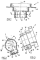
- the fixing device is intended for a vehicle steering column automobile. It includes an external element 2 and a internal element 4 having cylindrical walls respective 6, 8 with respective axis 10, 12.
- the element external 2 is adapted to surround the internal element 4 as in Figures 7 to 9 so that the two walls cylindrical 6, 8 are mutually coaxial and in look at each other.
- a face internal cylindrical 14 of the wall 6 of the element external 2 is then opposite an external face cylindrical 16 of the wall 8 of the internal element 4.
- the internal face 14 of the external element has a radius greater than a radius of the external face 16 of the element internal so that a slight radial clearance is then provided between them.
- the cylindrical wall 8 of the internal element 4 internally defines a suitable support duct 55 for the reception in the internal element of a support of the fixing device.
- the external element 2 and the internal element 4 each have a cleat 18, 19 extending radially to the axis 10, 12 projecting outwards of the associated cylindrical wall 6, 8.
- the cleat 19 is delimited externally by a flat bearing face or ramp 20 tangent to the face cylindrical 16, a rear face 22 not parallel to the support face 20 and parallel to axis 12, and one face lateral 24 joining the support face 20 and the face rear 22 and opposite to the cylindrical face 16.
- the cleat 18 is hollowed out so as to internally receive the cleat 19 of internal element 4 when it is received in the external element.
- the cleat 18 thus presents three internal faces of dimensions and arrangement homothetic with respect to the external faces 20, 22, 24 of the cleat 19 of the internal element. These three faces internal are a bearing face or ramp 26, a face rear 28 and a side face 30 having the same inclinations as their counterparts in the internal cleat 19.
- the two series of three faces are dimensioned so that the internal tab 19 can be received with play in the external cleat 18.
- the cylindrical wall 6 is hollowed out opposite cleat 18.
- the two tabs 18, 19 each have a cylindrical conduit 32, 34.
- the internal conduit 34 is smooth while the external conduit 32 is tapped. Sure the internal cleat 19, this conduit 34 is distant from the cylindrical wall 8.
- the conduits 32, 34 extend in a direction orthogonal to the longitudinal axes 10, 12 respective, in particular not secant with these axes and not parallel to them.
- the conduit 34 passes through the stopper right through.
- the conduit 32 passes through in part a front wall 36 of the cleat having the face internal support 26.
- the two conduits are adapted to extend coincidentally and coaxially when the internal cleat 19 is received in external cleat 18.
- the front wall 36 On the external cleat, the front wall 36 has a front external face 38 parallel to the internal face rear 28.
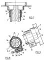
- the duct 32 of the front wall 36 extends long enough to allow pre-assembly a screw 39 in the duct 32 of the external cleat 18 of so that the conduit supports this screw on its own as in Figure 8.
- the internal duct 32 is arranged so that the screw 39 is received therein with a radial clearance important with respect to a screw axis.
- the internal element 4 comprises a profiled bead 40 with an arcuate profile, extending along a generator of the cylindrical wall 8, projecting from this one.
- the bead 40 is diametrically opposed to the internal cleat 19 on the one hand and on the other side of the longitudinal axis 12.
- the external element 2 has a local deformation profiled from its cylindrical wall 6, extending along a generator of the cylindrical wall and defining on the internal face 14 a profiled hollow 42 diametrically opposite to the external cleat 18 on the one hand and on the other side of the longitudinal axis 10.
- This hollow 42 has two substantially flat faces 44 inclined one by compared to each other.
- the internal element 4 has two planar edges end 46 perpendicular to the longitudinal axis 12 and parallel to each other.
- the external element 2 has a lower edge end plane 48 perpendicular to the longitudinal axis 10.
- the external element 2 has a flat upper wall of support 50 perpendicular to axis 10 and projecting internally and externally with respect to the cylindrical wall 6. This wall 50 has a central orifice 52.
- the element external 2 carries a flat plate 53 parallel to the support wall 50 and extending outwards in direction opposite to the longitudinal axis 10.
- the external element and the internal element are each in one piece.
- the element is fixed internal 4, for example by force, on an axial end upper of a steering column tube 54 in threading the tube 54 into the support duct 55 of the internal element 4, the upper edge 46 of the element internal 4 being coplanar with an upper edge of this tube, as shown in Figure 4.
- the steering column comprises a shaft 56 coaxial with tube 54, and extending therein with interposition between them several bearings such as the bearing 58. Then engage the lower end of the external element 2 on the internal element 4, coaxially, to slide the two elements 2, 4 relatively along their common longitudinal axis until the support wall 50 abuts against the upper edges of the internal element 4 and of the tube column 54.
- the asymmetrical shape of the cleats 18, 19 only one relative mounting position is possible for both elements. The cleats produce thus a polarizing effect.
- the element external 2 comprises an elongated straight arm 60 parallel to longitudinal axis 10 and offset laterally relative to this one.
- An upper end of the arm is fixed to the support wall 50, and one end lower arm carries a lug 62 arranged so that in the aforementioned relative assembly position of the two elements, the lug engages with the edge lower 46 of the internal element.
- lug 62 immobilizes the two sliding elements following axis 10, 12.
- the screw 39 is a self-tapping screw that digs its thread in the internal duct as it enters this one.
- the device is arranged in such a way that this maneuver has the effect of moving the two elements relatively so the cleat of the external element moves away from the axis 10 while the cleat of the internal element approaches by pushing radially the relief 40 in the recess 42 in support against the two faces 44 thereof.
- the two elements 2, 4 are then immobilized relative to each other without any play of any kind between them.
- the plate 53 can receive control switches 57 and levers 59 or other control devices connected and connected to these in the vicinity of the steering wheel 60 mounted at the top of the column.
- the device of the invention makes it possible to obtain easily precise angular positioning of the two relatively, and ultimately, platinum 53 elements by compared to steering wheel 60, the slightest defect in angular positioning between them detrimental to in contrast to the aesthetics of the control station.
- the internal element 4 can serve as direct support for bearing 58. It could be an element of anti-theft support. It can be integrated in one piece with the column tube 54. It may be in light alloy, aluminum, magnesium or even plastic material. It can be attached to tube 54 by crimping.
- the two fixing ducts can be smooth and associated with a self-tapping screw.
- the external conduit 32 could be smooth and the internal pipe 34 tapped.
- the conduit presenting a radial clearance with the screw could be the conduit internal. The relative displacement of the two elements may be free of play, if they are adapted to deform.
Landscapes
- Engineering & Computer Science (AREA)
- Chemical & Material Sciences (AREA)
- Combustion & Propulsion (AREA)
- Transportation (AREA)
- Mechanical Engineering (AREA)
- Steering Controls (AREA)
- Connection Of Plates (AREA)
- Mutual Connection Of Rods And Tubes (AREA)
Applications Claiming Priority (2)
| Application Number | Priority Date | Filing Date | Title |
|---|---|---|---|
| FR9800415A FR2773762B1 (fr) | 1998-01-16 | 1998-01-16 | Dispositif de fixation sur colonne de direction de vehicule automobile |
| FR9800415 | 1998-01-16 |
Publications (2)
| Publication Number | Publication Date |
|---|---|
| EP0930213A1 true EP0930213A1 (de) | 1999-07-21 |
| EP0930213B1 EP0930213B1 (de) | 2003-10-15 |
Family
ID=9521837
Family Applications (1)
| Application Number | Title | Priority Date | Filing Date |
|---|---|---|---|
| EP19990400083 Expired - Lifetime EP0930213B1 (de) | 1998-01-16 | 1999-01-14 | Befestigungseinrichtung für eine Kraftfahrzeuglenksäule |
Country Status (4)
| Country | Link |
|---|---|
| EP (1) | EP0930213B1 (de) |
| DE (1) | DE69912010T2 (de) |
| ES (1) | ES2207915T3 (de) |
| FR (1) | FR2773762B1 (de) |
Cited By (1)
| Publication number | Priority date | Publication date | Assignee | Title |
|---|---|---|---|---|
| FR2796892A1 (fr) * | 1999-07-28 | 2001-02-02 | Sc2N Sa | Systeme de fixation d'une platine de commande sur une colonne de direction de mise en oeuvre aisee |
Families Citing this family (1)
| Publication number | Priority date | Publication date | Assignee | Title |
|---|---|---|---|---|
| GB2368894B (en) * | 2000-11-14 | 2005-07-20 | Nastech Europ Ltd | Steering column assembly for a vehicle |
Citations (2)
| Publication number | Priority date | Publication date | Assignee | Title |
|---|---|---|---|---|
| GB1384691A (en) * | 1971-05-12 | 1975-02-19 | Lucas Industries Ltd | Sleeve clamps |
| EP0152311A2 (de) | 1984-01-20 | 1985-08-21 | Regie Nationale Des Usines Renault | Vorrichtung zur Befestigung und winklichen Einstellung einer Kunststoffplatte an einem zylindrischen Gegenstand |
-
1998
- 1998-01-16 FR FR9800415A patent/FR2773762B1/fr not_active Expired - Fee Related
-
1999
- 1999-01-14 DE DE69912010T patent/DE69912010T2/de not_active Expired - Lifetime
- 1999-01-14 ES ES99400083T patent/ES2207915T3/es not_active Expired - Lifetime
- 1999-01-14 EP EP19990400083 patent/EP0930213B1/de not_active Expired - Lifetime
Patent Citations (2)
| Publication number | Priority date | Publication date | Assignee | Title |
|---|---|---|---|---|
| GB1384691A (en) * | 1971-05-12 | 1975-02-19 | Lucas Industries Ltd | Sleeve clamps |
| EP0152311A2 (de) | 1984-01-20 | 1985-08-21 | Regie Nationale Des Usines Renault | Vorrichtung zur Befestigung und winklichen Einstellung einer Kunststoffplatte an einem zylindrischen Gegenstand |
Cited By (1)
| Publication number | Priority date | Publication date | Assignee | Title |
|---|---|---|---|---|
| FR2796892A1 (fr) * | 1999-07-28 | 2001-02-02 | Sc2N Sa | Systeme de fixation d'une platine de commande sur une colonne de direction de mise en oeuvre aisee |
Also Published As
| Publication number | Publication date |
|---|---|
| EP0930213B1 (de) | 2003-10-15 |
| FR2773762B1 (fr) | 2000-04-07 |
| ES2207915T3 (es) | 2004-06-01 |
| DE69912010D1 (de) | 2003-11-20 |
| FR2773762A1 (fr) | 1999-07-23 |
| DE69912010T2 (de) | 2004-08-05 |
Similar Documents
| Publication | Publication Date | Title |
|---|---|---|
| EP1241072B1 (de) | Verbindung eines Lenksäulenbügels mit einem Kraftfahrzeuglenkungsritzel | |
| FR2780756A1 (fr) | Systeme de blocage a boulon et ecrou | |
| WO2001002739A1 (fr) | Dispositif d'assemblage de deux pieces presentant un jeu de position | |
| FR3019601A1 (fr) | Systeme de fixation d'un objet sur un rail d'un support | |
| EP0706929B1 (de) | Vorrichtung zur Befestigung einer Lenkradnabe eines Kraftfahrzeuges an einer Lenksäule | |
| EP0930213B1 (de) | Befestigungseinrichtung für eine Kraftfahrzeuglenksäule | |
| FR2713187A1 (fr) | Ensemble de colonne de direction, notamment pour véhicule automobile. | |
| EP0508856A1 (de) | Sicherheitsbefestigungsanordnung für ein männliches Teil bie einem Bügel eines weiblichen Teils, verwendbar, insbesondere zum Verbinden von zwei Lenksäulenteilen eines Kraftfahrzeuges | |
| FR2953488A1 (fr) | Systeme de fixation d'un siege d'aeronef et siege correspondant | |
| EP1574422A1 (de) | Querträger eines Fahrzeugs und Fahrzeug mit einem solchen Querträger | |
| EP0491590B1 (de) | Befestigungsvorrichtung zum Halten einer Klimaanlage am Chassis eines Automobils | |
| EP1712804A1 (de) | Zustandshaltevorrichtung für Schraubmitteln | |
| WO2004054855A1 (fr) | Dispositif de fixation d’une platine de system d’essuyage d’un vehicule automobile | |
| EP0721875A1 (de) | Einstellbare Lenksäuleneinheit für ein Kraftfahrzeug | |
| FR2742823A1 (fr) | Dispositif d'entrainement a montage simplifie pour volet de reglage d'un flux d'air | |
| EP0192531A1 (de) | Lager, insbesondere für Zahnstangenlenkung | |
| EP1086879A1 (de) | Positionsblockiereinrichtung einer verstellbaren Fahrzeuglenksäule | |
| EP1043459B1 (de) | Befestigungseinrichtung für den Aussengriff einer Kraftfahrzeugtür | |
| FR2722749A1 (fr) | Attache elastique pour la fixation d'une ferrure de corps de colonne de direction de vehicule automobile, sur le reste de la structure de celui-ci | |
| EP1086878A1 (de) | Positionsblockiereinrichtung einer verstellbaren Lenksäule, insbesondere für ein Kraftfahrzeug | |
| EP2764188B1 (de) | Scharnieranordnung für die verbindung einer schwingtür eines kraftfahrzeugs | |
| FR2766025A1 (fr) | Boitier d'appareillage electrique pour cloison seche | |
| FR3162253A1 (fr) | Ensemble permettant un assemblage dans un espace encombre d’un accessoire sur un support | |
| FR2847954A1 (fr) | Dispositif d'assemblage et chemin de cables en comportant application | |
| FR2783227A1 (fr) | Systeme d'indexage de position pour le montage d'un volant sur un arbre de direction d'un ensemble de colonne de direction de vehicule automobile |
Legal Events
| Date | Code | Title | Description |
|---|---|---|---|
| PUAI | Public reference made under article 153(3) epc to a published international application that has entered the european phase |
Free format text: ORIGINAL CODE: 0009012 |
|
| AK | Designated contracting states |
Kind code of ref document: A1 Designated state(s): DE ES GB IT |
|
| AX | Request for extension of the european patent |
Free format text: AL;LT;LV;MK;RO;SI |
|
| 17P | Request for examination filed |
Effective date: 20000117 |
|
| AKX | Designation fees paid |
Free format text: DE ES GB IT |
|
| 17Q | First examination report despatched |
Effective date: 20011106 |
|
| GRAH | Despatch of communication of intention to grant a patent |
Free format text: ORIGINAL CODE: EPIDOS IGRA |
|
| GRAA | (expected) grant |
Free format text: ORIGINAL CODE: 0009210 |
|
| GRAS | Grant fee paid |
Free format text: ORIGINAL CODE: EPIDOSNIGR3 |
|
| AK | Designated contracting states |
Kind code of ref document: B1 Designated state(s): DE ES GB IT |
|
| REG | Reference to a national code |
Ref country code: GB Ref legal event code: FG4D Free format text: NOT ENGLISH |
|
| REF | Corresponds to: |
Ref document number: 69912010 Country of ref document: DE Date of ref document: 20031120 Kind code of ref document: P |
|
| GBT | Gb: translation of ep patent filed (gb section 77(6)(a)/1977) |
Effective date: 20040202 |
|
| REG | Reference to a national code |
Ref country code: ES Ref legal event code: FG2A Ref document number: 2207915 Country of ref document: ES Kind code of ref document: T3 |
|
| PLBE | No opposition filed within time limit |
Free format text: ORIGINAL CODE: 0009261 |
|
| STAA | Information on the status of an ep patent application or granted ep patent |
Free format text: STATUS: NO OPPOSITION FILED WITHIN TIME LIMIT |
|
| 26N | No opposition filed |
Effective date: 20040716 |
|
| PGFP | Annual fee paid to national office [announced via postgrant information from national office to epo] |
Ref country code: GB Payment date: 20090109 Year of fee payment: 11 |
|
| GBPC | Gb: european patent ceased through non-payment of renewal fee |
Effective date: 20100114 |
|
| PG25 | Lapsed in a contracting state [announced via postgrant information from national office to epo] |
Ref country code: GB Free format text: LAPSE BECAUSE OF NON-PAYMENT OF DUE FEES Effective date: 20100114 |
|
| PGFP | Annual fee paid to national office [announced via postgrant information from national office to epo] |
Ref country code: DE Payment date: 20120118 Year of fee payment: 14 |
|
| PGFP | Annual fee paid to national office [announced via postgrant information from national office to epo] |
Ref country code: IT Payment date: 20120126 Year of fee payment: 14 |
|
| PGFP | Annual fee paid to national office [announced via postgrant information from national office to epo] |
Ref country code: ES Payment date: 20120126 Year of fee payment: 14 |
|
| PG25 | Lapsed in a contracting state [announced via postgrant information from national office to epo] |
Ref country code: DE Free format text: LAPSE BECAUSE OF NON-PAYMENT OF DUE FEES Effective date: 20130801 |
|
| REG | Reference to a national code |
Ref country code: DE Ref legal event code: R119 Ref document number: 69912010 Country of ref document: DE Effective date: 20130801 |
|
| PG25 | Lapsed in a contracting state [announced via postgrant information from national office to epo] |
Ref country code: IT Free format text: LAPSE BECAUSE OF NON-PAYMENT OF DUE FEES Effective date: 20130114 |
|
| REG | Reference to a national code |
Ref country code: ES Ref legal event code: FD2A Effective date: 20140324 |
|
| PG25 | Lapsed in a contracting state [announced via postgrant information from national office to epo] |
Ref country code: ES Free format text: LAPSE BECAUSE OF NON-PAYMENT OF DUE FEES Effective date: 20130115 |