EP0930244A1 - Ensemble de conditionnement et de distribution sous pression, à mise sous pression extemporanée - Google Patents
Ensemble de conditionnement et de distribution sous pression, à mise sous pression extemporanée Download PDFInfo
- Publication number
- EP0930244A1 EP0930244A1 EP98403197A EP98403197A EP0930244A1 EP 0930244 A1 EP0930244 A1 EP 0930244A1 EP 98403197 A EP98403197 A EP 98403197A EP 98403197 A EP98403197 A EP 98403197A EP 0930244 A1 EP0930244 A1 EP 0930244A1
- Authority
- EP
- European Patent Office
- Prior art keywords
- valve
- container
- compartment
- packaging
- assembly according
- Prior art date
- Legal status (The legal status is an assumption and is not a legal conclusion. Google has not performed a legal analysis and makes no representation as to the accuracy of the status listed.)
- Withdrawn
Links
Images


Classifications
-
- B—PERFORMING OPERATIONS; TRANSPORTING
- B65—CONVEYING; PACKING; STORING; HANDLING THIN OR FILAMENTARY MATERIAL
- B65D—CONTAINERS FOR STORAGE OR TRANSPORT OF ARTICLES OR MATERIALS, e.g. BAGS, BARRELS, BOTTLES, BOXES, CANS, CARTONS, CRATES, DRUMS, JARS, TANKS, HOPPERS, FORWARDING CONTAINERS; ACCESSORIES, CLOSURES, OR FITTINGS THEREFOR; PACKAGING ELEMENTS; PACKAGES
- B65D83/00—Containers or packages with special means for dispensing contents
- B65D83/14—Containers for dispensing liquid or semi-liquid contents by internal gaseous pressure, i.e. aerosol containers comprising propellant
- B65D83/60—Containers for dispensing liquid or semi-liquid contents by internal gaseous pressure, i.e. aerosol containers comprising propellant with contents and propellant separated
- B65D83/64—Containers for dispensing liquid or semi-liquid contents by internal gaseous pressure, i.e. aerosol containers comprising propellant with contents and propellant separated by pistons
Definitions
- the present application relates to a packaging and pressure distribution of a product, in particular a cosmetic product.
- the invention is particularly suitable for packaging and pressure distribution of certain hair application products, such as certain coloring products, in particular tone on tone coloring.
- oxidation dyes called "tone on tone" which are packaged in cans containing an aluminum pocket delimiting two isolated volumes one from the other: a first volume in communication with a head of distribution, and containing the dye, and a second volume, containing a gas propellant, in particular butane 3.2.
- a gas propellant in particular butane 3.2.
- Such products are very sensitive to light and oxygen.
- the dye is mixed with a cream oxidant packaged in a separate bottle. Besides the unreliability, a such packaging is extremely expensive.
- piston drums or other means of separation, comprising a drum surmounted by a valve and a dispensing head.
- the product is pressurized at by means of a propellant gas kept isolated from the product by a sliding piston tightly in the container.
- the seal is ensured by an O-ring arranged at the periphery of the piston and by a lip scraper, in intimate support with the interior walls of the container.
- Patent application EP-A-0 642 839 describes a device for distributing and packaging of a fluid product contained in a pressurized container, using a propellant contained in a compartment of the container, isolated from the product to be dispensed by a piston.
- the container is topped with a manual actuation.
- the compartment containing the gas thruster empties into gas by means of a micro-slot, so that at the end the compartment has been at atmospheric pressure for some time.
- the opening and closing of the dispensing valve of the product are produced by an actuating mechanism, in the form of a push button, controlled independently of the pressure at inside said compartment containing the propellant gas.
- Such a design multiplies the gestures to use.
- a packaging and pressure distribution of a product in particular a cosmetic
- a product in particular a cosmetic
- a cosmetic comprising a first container, surmounted by a first valve able to pass from a position closing in an open position for dispensing the product, said container defining two compartments kept isolated from each other tightly, in particular by a movable piston, a first compartment containing the product, and a second compartment for receiving a propellant capable of pressurizing the product via the movable piston, the second compartment being, in the closed position of the first valve, substantially at atmospheric pressure, the opening and closing of the first valve being pressure controlled inside the second compartment.
- the closure of the first valve can be caused by the passage to the atmospheric pressure of the second compartment.
- at closing by interrupting the actuation command, it causes a on the one hand, putting the second compartment at atmospheric pressure and on the other share, the closure of said first valve
- a single command of actuation can cause on the one hand, the setting under extemporaneous pressure of the product and on the other hand, the opening of the first valve.
- both the opening and the closing of the first valve are controlled by the pressure prevailing inside the second compartment.
- the gesture is simple, since both at the opening and at closing, a single gesture is enough on the one hand, to pressurize the second compartment and secondly, to cause the opening of the first valve, respectively, on the one hand, to depressurize the second compartment and on the other hand, to cause the closure of the first valve.
- movable piston is the preferred means of separation
- other means in particular a flexible pocket, can be used to separate the product from the propellant.
- the propellant gas is contained under pressure in a second container capable of being selectively placed in communication with the first to be able to pressurize the second compartment for the pressure distribution of the product, means being provided for interrupt the communication between the first container and the second, and put the second compartment at atmospheric pressure between two uses, when the first valve is in the closed position.
- said second container is surmounted by a second valve able to pass from a closed position to an open position, said second valve being connected to an outlet channel which, in position opening of said second valve, is in sealed communication with the second compartment goes an inlet of said second compartment, so as to allow the passage of the propellant gas from the second container to the second compartment of the first container, said inlet opening being in communication with the outside when the second valve is in the position of closing, so as to put the second compartment under pressure atmospheric.
- the waterproof communication is carried out by means of a coupling element, preferably flexible, surmounting said outlet channel and intended to come into watertight support all around the intake orifice when a pressure is exerted on one end of the second container opposite to said second valve, said sealed support ceasing when the second valve passes through elastic return in closed position.
- a coupling element preferably flexible, surmounting said outlet channel and intended to come into watertight support all around the intake orifice when a pressure is exerted on one end of the second container opposite to said second valve, said sealed support ceasing when the second valve passes through elastic return in closed position.
- the element of coupling can be made of elastomeric material.
- the inlet is preferably made in the bottom of the first container, means being provided for holding the second container in position relative to the first. This produces a unitary assembly, easy to handle, and ready to use, without any prior manipulation.
- Such holding means may consist of a sleeve integral with the first container, and one end of which is opposite the end of the second container opposite said second valve is open at least partially, said second container being mounted to slide inside the sleeve, on a stroke at least equal to the actuation height of the second valve.
- the clearance existing between the internal walls of the sleeve and the second container provides enough space for, when breaking between the first container and the second, allow the contained gas in the second compartment to escape, goes the open end of the sleeve, allowing to put the second compartment under pressure atmospheric.
- said sleeve is made integral with the first container by self-tightening assembly, breakdown, gluing or welding.
- Such an arrangement can be removable, in particular to limit the size in the storage position, or, if applicable, to authorize the refueling of the second propellant container.
- the first valve passes into the open position when the pressure inside the first compartment, under the action of the propellant, reaches a predetermined value, and goes into the closed position under the action of elastic return means when the pressure inside the first compartment drops below said predetermined value.
- a valve can be of the ball type.
- said second container can be removable and / or rechargeable with propellant gas. Indeed, it can be sold as reusable accessory for emptying several packagings sold separately. Furthermore, it can be provided that the second container does not contains sufficient gas for only a fraction of the content of the first. Indeed, in the case of a product to be distributed from dosed manner, the second container can advantageously contain the amount of propellant needed to dispense a dose of product.
- said second container is of the type comprising a body and a bottom, the body forming a valve holder cup for the second valve, the body cooperating with the bottom to form on the one hand a reservoir of said propellant gas, and on the other hand the valve body for said second valve.
- the product can be a hair application product, in particular a dye. oxidation.
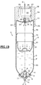
- the packaging and pressure distribution 1 mainly comprises a container 2 of axis X, by example in painted aluminum on its internal face.
- the container has a body 3, of generally cylindrical section, and one end 4 of which forms a shoulder, ending with an opening delimited by a roll of crimping 5, on which is mounted, in particular by clipping, a valve 6.
- the valve 6 has a sealing skirt 7 able to cooperate in a sealed manner with the edges delimiting the opening of the can 2.
- the valve has a central chimney defining an axial channel 8 inside which is disposed a ball 9 of diameter smaller than the internal diameter of the axial channel 8, so the product can flow between the ball 9 and the walls of the axial channel 8.
- the lower end of the axial channel 8 is of frustoconical section, less than the diameter of the ball 9 so as to form a seat for the ball.
- the spring is held in abutment on the one hand against the ball 9, and on the other part against the part 11, which is mounted by snap-fastening on the valve 6.
- the ball 9 is sealed against its seat, thereby preventing the product from exit.
- the pressurized product (P) can flow between the ball 9 and the internal walls of the axial channel 8.
- the other end 13 of the container 2 is closed by a bottom 14, provided in its center of an orifice 15 the function of which will be detailed below.
- a piston 16 mounted with a sliding support watertight on the internal walls of the container 2.
- the piston delimits a first upper compartment or volume 33 containing the product (P), and a second compartment or lower volume 34 intended to receive the propellant gas.
- the seal around the piston 16 is ensured by an O-ring 17, thus than a scraper lip 18.
- the profile of the piston 16 is chosen so appropriate in order to optimize the emptying rate of container 2
- the product to be dispensed (P) is contained in the upper volume 33 of the container 2, between the piston 16 and the valve 6.
- the piston is arranged in the low position. Liquid is introduced through the opening delimited by the crimping roll 5. The valve is then clipped so final on container 2.
- the assembly illustrated according to this embodiment comprises a second container 20, located under the first, and containing a pressurized gas.
- a container 20 is surmounted by an emerging rod 21 of a depression valve 30, biased in the closed position by an elastic return means.
- On the stem valve 21 is mounted a flexible connector 22 defining a channel 23 and one of which free end 32 is disposed opposite the orifice 15 formed in the bottom 14 of the container 2.
- the container 20 is held in position in a sleeve 24 whose one end 25 is forcibly mounted on the end 13 of the container 2.
- a shoulder 31 limits the depth of insertion of the container 2 into the sleeve 24.
- the other end of the sleeve 26 has an annular rim 27 of internal diameter smaller than the external diameter of the container 20, so that maintain the latter.
- the rim 27 delimits an opening 28, allowing to access the bottom 29 of the container 20.
- the inside diameter of the sleeve 24 is slightly larger than the outside diameter of the container 20, so that the latter can slide freely inside, over a height at least equal at the actuation height of the valve stem 21.
- the axial height of sleeve 24 is sufficient so that in this position, the valve 30 is in the closed position, and the free end 32 of the flexible connector 22 is not in leaktight support all around the orifice 15, so that in this position, the part 34 of the container located under the piston 16 is substantially at atmospheric pressure.
- the user turns over the set 1 in placing a finger on the bottom 29 of the container 20, through the opening 28. It press lightly on the bottom 29 of the container 20. This pressure causes a movement of the container 20 in the sleeve 24, so that the end 32 of the flexible connector 22 is in leaktight support all around the orifice 15 of the container 2.
- the valve stem 21 By continuing to apply pressure to the bottom 29, it causes the valve stem 21 to sink, and the valve 30 to open.
- propellant gas exits under pressure through the emerging rod 21, passes in the flexible connector 22, and enters the lower volume 34 of the can 2, goes orifice 15. The propellant gas expands and then fills said lower volume 34, located under the piston 16.
- the formula keeps its clear appearance.
- the amount of propellant contained in container 20 can be chosen to be sufficient to empty the entire container 2. Alternatively, provision may be made for replace container 20, when it is empty, to replace it with a another full container. Alternatively we can plan to reload the container 20, either by its upper valve, or by an auxiliary orifice, provided by example at the bottom of container 20.
- FIG. 2 shows in more detail one mode of realization of a container 20 which can be advantageously used in the assembly according to the invention.
- a container 20 mainly comprises a body 200, one end wall of which forms a cup 201 for the valve 30.
- the end of the body, opposite the valve holder cup, is closed by a bottom 211, which also forms an axial chimney 209 defining a valve body 202 for said valve 30.
- the bottom 211 can be welded, slammed or screwed onto the body 200.
- the body 200 and the bottom 211 define first a reservoir 203 for the propellant, and secondly a valve body 202.
- the reservoir 203 and the valve body are in communication by a passage 204.
- the valve stem 21 has an emerging end outside the valve body 202, crossed by an axial channel 205 opening laterally on the valve stem, via a passage 206, substantially halfway up the stem, and one end located inside the valve body, which end is mounted on a spring 208 so as to maintain by elastic return the passage 204 opposite a seal 207, thereby urging the valve into closed position.
- a filling opening 210, closed by a ball valve is provided in the bottom 211 of the container 20.
- An attached removable bottom 29 is provided so as to define a flat bearing surface.
- the container 20 is obtained entirely from molding of a thermoplastic material. A a more detailed description of such a container is given in patent FR 2 741 047 on behalf of the plaintiff.
Landscapes
- Chemical & Material Sciences (AREA)
- Dispersion Chemistry (AREA)
- Engineering & Computer Science (AREA)
- Mechanical Engineering (AREA)
- Containers And Packaging Bodies Having A Special Means To Remove Contents (AREA)
Abstract
Description
Claims (13)
- Ensemble de conditionnement et de distribution sous pression (1) d'un produit (P), notamment cosmétique, comportant un premier récipient (2), surmonté d'une première valve (6) apte à passer d'une position de fermeture à une position d'ouverture en vue de la distribution du produit (P), ledit récipient (2) définissant deux compartiments (33, 34) maintenus isolés l'un de l'autre de manière étanche, notamment par un piston mobile (16), un premier compartiment (33) contenant le produit (P), et un second compartiment (34) pour recevoir un gaz propulseur apte à pressuriser le produit va le piston mobile (16), le second compartiment (34) étant, en position de fermeture de la valve (6), sensiblement à la pression atmosphérique, l'ouverture et/ou la fermeture de la première valve (6) étant commandée par la pression à l'intérieur du second compartiment (34).
- Ensemble de conditionnement et de distribution selon la revendication 1 caractérisé en ce que la fermeture de la valve (6) est provoquée par le passage à la pression atmosphérique du second compartiment (34).
- Ensemble de conditionnement et de distribution selon la revendication 1 ou 2 caractérisé en ce que le gaz propulseur est contenu sous pression dans un second récipient (20) apte à être mis sélectivement en communication avec le premier (2) pour pouvoir pressuriser le second compartiment (34) en vue de la distribution sous pression du produit, des moyens (30, 15, 22, 24, 208) étant prévus pour interrompre la communication entre le premier récipient (2) et le second (20), et mettre le second compartiment (34) à la pression atmosphérique lorsque la première valve (6) est en position de fermeture.
- Ensemble de conditionnement et de distribution selon la revendication 3 caractérisé en ce que ledit second récipient (20) est surmonté d'une seconde valve (30) apte à passer d'une position de fermeture à une position d'ouverture, ladite seconde valve (30) étant reliée à un canal de sortie (21) qui, en position d'ouverture de ladite seconde valve (30), est en communication étanche avec le second compartiment (34) via un orifice d'admission (15) dudit second compartiment (34), de manière à permettre le passage du gaz propulseur depuis le second récipient (20) vers le second compartiment (34) du premier récipient (2), ledit orifice d'admission (15) étant en communication avec l'extérieur lorsque la seconde valve (30) est en position de fermeture, de manière à mettre le second compartiment (34) à la pression atmosphérique.
- Ensemble de conditionnement et de distribution selon la revendication 4 caractérisé en ce que la communication étanche est réalisée au moyen d'un élément de couplage (22) surmontant ledit canal de sortie (21) et destiné à venir en appui étanche tout autour de l'orifice d'admission (15) lorsqu'une pression est exercée sur une extrémité (29) du second récipient (20) opposée à ladite seconde valve (30), ledit appui étanche cessant lorsque la seconde valve (30) passe par rappel élastique en position de fermeture.
- Ensemble de conditionnement et de distribution selon la revendication 4 ou 5 caractérisé en ce que l'orifice d'admission (15) est ménagé dans le fond (14) du premier récipient (2), des moyens (24) étant prévus pour maintenir le second récipient (20) en position par rapport au premier (2).
- Ensemble de conditionnement et de distribution selon la revendication 6 caractérisé en ce que les moyens de maintien (24) sont constitués d'un manchon (24) solidaire du premier récipient (2), et dont une extrémité (26) située en regard de l'extrémité (29) du second récipient opposée à ladite seconde valve (30) est ouverte au moins partiellement, ledit second récipient (20) étant monté à coulisse à l'intérieur du manchon, sur une course au moins égale à la hauteur d'actionnement de la seconde valve (30).
- Ensemble de conditionnement et de distribution selon la revendication 7 caractérisé en ce que ledit manchon (24) est rendu solidaire du premier récipient (2) par montage auto-serrant, claquage, collage ou soudure.
- Ensemble de conditionnement et de distribution selon l'une quelconque des revendications 1 à 8 caractérisé en ce que la première valve (6) passe en position d'ouverture lorsque la pression à l'intérieur du premier compartiment (33), sous l'action du gaz propulseur, atteint une valeur prédéterminée, et passe en position de fermeture sous l'action de moyens de rappel élastiques (10) lorsque la pression à l'intérieur du premier compartiment (33) descend en dessous de ladite valeur prédéterminée.
- Ensemble de conditionnement et de distribution selon la revendication 9 caractérisé en ce que ladite première valve (6) est du type à bille (9).
- Ensemble de conditionnement et de distribution selon l'une quelconque des revendications 3 à 10 caractérisé en ce que ledit second récipient (20) est amovible et/ou rechargeable en gaz propulseur.
- Ensemble de conditionnement et de distribution selon l'une quelconque des revendications 3 à 11 caractérisé en ce que ledit second récipient (20) est de type comprenant un corps (200) et un fond (211), le corps (200) formant une coupelle porte-valve (201) pour la seconde valve (30), le corps (200) coopérant avec le fond (211) pour former d'une part un réservoir (203) dudit gaz propulseur, et d'autre part le corps de valve (202) pour ladite seconde valve (30).
- Utilisation d'un ensemble selon l'une quelconque des revendications 1 à 12 pour le conditionnement et la distribution d'un produit d'application capillaire, notamment un colorant d'oxydation.
Applications Claiming Priority (2)
| Application Number | Priority Date | Filing Date | Title |
|---|---|---|---|
| FR9800315 | 1998-01-14 | ||
| FR9800315A FR2773543B1 (fr) | 1998-01-14 | 1998-01-14 | Ensemble de conditionnement et de distribution sous pression, a mise sous pression extemporanee |
Publications (1)
| Publication Number | Publication Date |
|---|---|
| EP0930244A1 true EP0930244A1 (fr) | 1999-07-21 |
Family
ID=9521758
Family Applications (1)
| Application Number | Title | Priority Date | Filing Date |
|---|---|---|---|
| EP98403197A Withdrawn EP0930244A1 (fr) | 1998-01-14 | 1998-12-17 | Ensemble de conditionnement et de distribution sous pression, à mise sous pression extemporanée |
Country Status (3)
| Country | Link |
|---|---|
| US (1) | US6131776A (fr) |
| EP (1) | EP0930244A1 (fr) |
| FR (1) | FR2773543B1 (fr) |
Cited By (2)
| Publication number | Priority date | Publication date | Assignee | Title |
|---|---|---|---|---|
| DE102014112595A1 (de) * | 2014-09-02 | 2016-03-03 | Reinhard Caliebe | Dose für ein medizinisches, pharmazeutisches oder kosmetisches Fluid |
| WO2022018205A1 (fr) * | 2020-07-22 | 2022-01-27 | Innovolo Limited | Bombe aérosol |
Families Citing this family (14)
| Publication number | Priority date | Publication date | Assignee | Title |
|---|---|---|---|---|
| NL1009292C1 (nl) * | 1998-05-29 | 1999-11-30 | Packaging Tech Holding Sa | Drukcontrole-inrichting voor het behouden van een constante vooraf bepaalde druk in een container. |
| DE29905147U1 (de) * | 1999-03-23 | 2000-08-03 | EGS Elektro- und Hausgerätewerk Suhl GmbH, 98544 Zella-Mehlis | Über Luftdruck entleerbarer Behälter |
| JP3626367B2 (ja) * | 1999-05-07 | 2005-03-09 | 武蔵エンジニアリング株式会社 | 液体ディスペンサーのシリンジ用プランジャー |
| DE20005484U1 (de) * | 2000-03-23 | 2000-07-06 | Aerosol Technik Lindal Gmbh, 23843 Bad Oldesloe | Spenderpackung |
| FR2840212B1 (fr) * | 2002-05-31 | 2005-09-16 | Oreal | Dispositif aerosol a deux compartiments comprenant une composition de traitement capillaire et procede de traitement capillaire |
| US7157076B2 (en) * | 2002-05-31 | 2007-01-02 | L'oreal | Aerosol device comprising a hair treatment composition, and hair treatment process |
| US10221059B2 (en) * | 2004-03-31 | 2019-03-05 | Ch&I Technologies, Inc. | Refillable material transfer system |
| US7753239B2 (en) * | 2007-04-17 | 2010-07-13 | Chang Hsu-Pin | Pressurized water container with water chamber replacement arrangement |
| US20090283550A1 (en) * | 2008-05-16 | 2009-11-19 | Kimball James F | Extreme Barrier Metal Piston and Container Utilizing Same |
| EP2382450A4 (fr) * | 2008-12-23 | 2015-01-07 | C H & I Tech Inc | Système et procédé de recharge d'un emballage pour des produits de consommation |
| CH700392B1 (de) * | 2009-02-06 | 2012-12-31 | Gerhard Obrist | Abgabevorrichtung für die dosierte Abgabe einer Flüssiggasformulierung und Verfahren zur Herstellung der Abgabevorrichtung. |
| US9534831B2 (en) * | 2010-10-29 | 2017-01-03 | Whirlpool Corporation | Liquid dispenser with collapsible container |
| WO2018094740A1 (fr) * | 2016-11-28 | 2018-05-31 | L'oreal | Dispositif de conditionnement et de distribution d'un produit comprenant un piston mobile |
| US11312564B2 (en) * | 2018-08-31 | 2022-04-26 | Michael C. Ryan | Sustainable reservoir-based storage, transport, and delivery system |
Citations (5)
| Publication number | Priority date | Publication date | Assignee | Title |
|---|---|---|---|---|
| BE757134A (fr) * | 1970-09-21 | 1971-04-06 | Ici Ltd | Distributeur de substances fluides. |
| US3788525A (en) * | 1973-03-08 | 1974-01-29 | Ciba Geigy Corp | Compressed air aspirating and propellant actuated fluid product dispenser |
| FR2246468A1 (fr) * | 1973-10-03 | 1975-05-02 | Fischbach A Kunststoff Kg | |
| US4197884A (en) * | 1975-12-08 | 1980-04-15 | Dispenser Corporation | Airless sprayer and pressurizing system |
| EP0642839A1 (fr) * | 1993-09-10 | 1995-03-15 | L'oreal | Procédé et dispositif de distribution et de conditionnement d'un produit fluide contenu dans un récipient pressurisé à l'aide d'un gaz propulseur |
Family Cites Families (2)
| Publication number | Priority date | Publication date | Assignee | Title |
|---|---|---|---|---|
| GB384691A (en) * | 1931-07-08 | 1932-12-15 | Imp And Internat Comm Ltd | Improvements relating to telegraph signalling apparatus |
| CA2013636A1 (fr) * | 1989-04-06 | 1990-10-06 | Sang I. Han | Dispositif jetable pour l'irrigation sous pression des blessures |
-
1998
- 1998-01-14 FR FR9800315A patent/FR2773543B1/fr not_active Expired - Fee Related
- 1998-12-17 EP EP98403197A patent/EP0930244A1/fr not_active Withdrawn
-
1999
- 1999-01-14 US US09/231,872 patent/US6131776A/en not_active Expired - Fee Related
Patent Citations (5)
| Publication number | Priority date | Publication date | Assignee | Title |
|---|---|---|---|---|
| BE757134A (fr) * | 1970-09-21 | 1971-04-06 | Ici Ltd | Distributeur de substances fluides. |
| US3788525A (en) * | 1973-03-08 | 1974-01-29 | Ciba Geigy Corp | Compressed air aspirating and propellant actuated fluid product dispenser |
| FR2246468A1 (fr) * | 1973-10-03 | 1975-05-02 | Fischbach A Kunststoff Kg | |
| US4197884A (en) * | 1975-12-08 | 1980-04-15 | Dispenser Corporation | Airless sprayer and pressurizing system |
| EP0642839A1 (fr) * | 1993-09-10 | 1995-03-15 | L'oreal | Procédé et dispositif de distribution et de conditionnement d'un produit fluide contenu dans un récipient pressurisé à l'aide d'un gaz propulseur |
Cited By (3)
| Publication number | Priority date | Publication date | Assignee | Title |
|---|---|---|---|---|
| DE102014112595A1 (de) * | 2014-09-02 | 2016-03-03 | Reinhard Caliebe | Dose für ein medizinisches, pharmazeutisches oder kosmetisches Fluid |
| WO2022018205A1 (fr) * | 2020-07-22 | 2022-01-27 | Innovolo Limited | Bombe aérosol |
| GB2597484A (en) * | 2020-07-22 | 2022-02-02 | Innovolo Ltd | Aerosol canister |
Also Published As
| Publication number | Publication date |
|---|---|
| US6131776A (en) | 2000-10-17 |
| FR2773543A1 (fr) | 1999-07-16 |
| FR2773543B1 (fr) | 2000-02-18 |
Similar Documents
| Publication | Publication Date | Title |
|---|---|---|
| CA2334413C (fr) | Distributeur pour le stockage d'au moins deux composants et la distribution selective soit d'un constituant seul, soit de leur melange et procede pour sa mise en oeuvre | |
| EP0930244A1 (fr) | Ensemble de conditionnement et de distribution sous pression, à mise sous pression extemporanée | |
| EP0626210B1 (fr) | Dispositif de distribution d'une dose de volume déterminé d'un produit liquide ou pâteux | |
| EP1288142B1 (fr) | Dispositif pour le conditionnement et la distribution sous pression d'un produit | |
| EP0307310B1 (fr) | Vaporisateur du type pompe manuelle à précompression pour utilisation avec un gaz propulseur | |
| EP1156300B1 (fr) | Embout doseur et ensemble de distribution équipé d'un tel embout | |
| CA2299163C (fr) | Ensemble pour le conditionnement et la distribution sous pression d'un produit, notamment cosmetique | |
| FR2774077A1 (fr) | Valve a regulation de debit de sortie, et recipient equipe d'une telle valve | |
| EP0589029B1 (fr) | Procede pour realiser un melange extemporane d'au moins deux composants, liquides ou pateux, et bidon pressurise pour mettre en oeuvre un tel procede | |
| EP1186544A1 (fr) | Dispositif pour le conditionnement séparé et la sortie conjointe de deux produits à mélanger de façon extemporanée | |
| CA2305005A1 (fr) | Dispositif pour le melange extemporane d'au moins deux produits dont un est notamment une poudre | |
| EP0765822B1 (fr) | Récipient distributeur pour un produit liquide sous pression muni d'un dispositif de décharge de gaz | |
| FR2816290A1 (fr) | Dispositif de conditionnement et de distribution sous pression d'un produit | |
| FR2802515A1 (fr) | Ensemble pour le conditionnement et la distribution sous pression d'un produit, utilisant un propulseur conditionne separement du produit a distribuer | |
| EP0778225B1 (fr) | Récipient aérosol | |
| EP0526811A2 (fr) | Dispositif pour le conditionnement et la distribution de produits pâteux ou liquides | |
| CA2108453A1 (fr) | Recipient distributeur de fluide | |
| FR2705590A1 (fr) | Dispositif de distribution de liquide utilisable en position droite et ne comportant pas de tube-plongeur. | |
| EP2397422B1 (fr) | Système de distribution d'un produit fluide | |
| EP1256526A1 (fr) | Dispositif pour le conditionnement séparé de deux produits, et leur distribution sous pression, de manière séparée ou en mélange | |
| FR3066758A1 (fr) | Recipient pour emballer un premier fluide comprenant une capsule pour emballer un deuxieme fluide, et une capsule adaptee pour ledit recipient | |
| WO2020193918A1 (fr) | Capsule adaptee pour recevoir un fluide et ensemble comprenant un recipient et ladite capsule | |
| CA2224502C (fr) | Dispositif pressurise a deux valves | |
| EP1149775A1 (fr) | Récipient aérosol équipé d'une valve améliorée | |
| FR2671538A1 (fr) | Dispositif distributeur et doseur de produit. |
Legal Events
| Date | Code | Title | Description |
|---|---|---|---|
| PUAI | Public reference made under article 153(3) epc to a published international application that has entered the european phase |
Free format text: ORIGINAL CODE: 0009012 |
|
| AK | Designated contracting states |
Kind code of ref document: A1 Designated state(s): DE ES FR GB IT |
|
| AX | Request for extension of the european patent |
Free format text: AL;LT;LV;MK;RO;SI |
|
| 17P | Request for examination filed |
Effective date: 20000121 |
|
| AKX | Designation fees paid |
Free format text: DE ES FR GB IT |
|
| 17Q | First examination report despatched |
Effective date: 20020417 |
|
| GRAP | Despatch of communication of intention to grant a patent |
Free format text: ORIGINAL CODE: EPIDOSNIGR1 |
|
| RTI1 | Title (correction) |
Free format text: UNIT FOR STORING AND DISPENSING A PRODUCT UNDER PRESSURE, WHEREBY AN EXTEMPORANEOUS PRESSURIZATION IS ACHIEVED |
|
| RTI1 | Title (correction) |
Free format text: UNIT FOR STORING AND DISPENSING A PRODUCT UNDER PRESSURE, WHEREBY AN EXTEMPORANEOUS PRESSURIZATION IS ACHIEVED |
|
| GRAS | Grant fee paid |
Free format text: ORIGINAL CODE: EPIDOSNIGR3 |
|
| STAA | Information on the status of an ep patent application or granted ep patent |
Free format text: STATUS: THE APPLICATION IS DEEMED TO BE WITHDRAWN |
|
| 18D | Application deemed to be withdrawn |
Effective date: 20040311 |