EP0930247A1 - Tapis de transport et système pour transporter des produits - Google Patents
Tapis de transport et système pour transporter des produits Download PDFInfo
- Publication number
- EP0930247A1 EP0930247A1 EP99200150A EP99200150A EP0930247A1 EP 0930247 A1 EP0930247 A1 EP 0930247A1 EP 99200150 A EP99200150 A EP 99200150A EP 99200150 A EP99200150 A EP 99200150A EP 0930247 A1 EP0930247 A1 EP 0930247A1
- Authority
- EP
- European Patent Office
- Prior art keywords
- conveying
- conveyor mat
- conveying direction
- modules
- hinge
- Prior art date
- Legal status (The legal status is an assumption and is not a legal conclusion. Google has not performed a legal analysis and makes no representation as to the accuracy of the status listed.)
- Granted
Links
- 239000004033 plastic Substances 0.000 claims abstract description 16
- 239000011521 glass Substances 0.000 claims description 41
- 238000002156 mixing Methods 0.000 claims description 11
- 239000000203 mixture Substances 0.000 claims description 5
- 239000004743 Polypropylene Substances 0.000 claims description 3
- -1 polypropylene Polymers 0.000 claims description 3
- 229920001155 polypropylene Polymers 0.000 claims description 3
- 239000011213 glass-filled polymer Substances 0.000 claims description 2
- 238000005192 partition Methods 0.000 claims description 2
- 239000000047 product Substances 0.000 description 35
- 239000012634 fragment Substances 0.000 description 26
- 101100491335 Caenorhabditis elegans mat-2 gene Proteins 0.000 description 19
- XLYOFNOQVPJJNP-UHFFFAOYSA-N water Substances O XLYOFNOQVPJJNP-UHFFFAOYSA-N 0.000 description 12
- 238000005452 bending Methods 0.000 description 4
- 230000000694 effects Effects 0.000 description 4
- 239000000463 material Substances 0.000 description 4
- 238000004904 shortening Methods 0.000 description 3
- 230000008901 benefit Effects 0.000 description 2
- 230000015572 biosynthetic process Effects 0.000 description 2
- 238000003780 insertion Methods 0.000 description 2
- 230000037431 insertion Effects 0.000 description 2
- 238000009928 pasteurization Methods 0.000 description 2
- 101100495270 Caenorhabditis elegans cdc-26 gene Proteins 0.000 description 1
- 230000009471 action Effects 0.000 description 1
- 235000013361 beverage Nutrition 0.000 description 1
- 230000000903 blocking effect Effects 0.000 description 1
- 239000006227 byproduct Substances 0.000 description 1
- 230000008859 change Effects 0.000 description 1
- 238000010276 construction Methods 0.000 description 1
- 230000008878 coupling Effects 0.000 description 1
- 238000010168 coupling process Methods 0.000 description 1
- 238000005859 coupling reaction Methods 0.000 description 1
- 230000007423 decrease Effects 0.000 description 1
- 230000003247 decreasing effect Effects 0.000 description 1
- 230000000994 depressogenic effect Effects 0.000 description 1
- 238000007599 discharging Methods 0.000 description 1
- 239000004744 fabric Substances 0.000 description 1
- 239000003365 glass fiber Substances 0.000 description 1
- 238000010438 heat treatment Methods 0.000 description 1
- 230000007246 mechanism Effects 0.000 description 1
- 239000002184 metal Substances 0.000 description 1
- 230000008439 repair process Effects 0.000 description 1
- 238000007665 sagging Methods 0.000 description 1
- 229910001220 stainless steel Inorganic materials 0.000 description 1
- 239000010935 stainless steel Substances 0.000 description 1
- 230000007704 transition Effects 0.000 description 1
Images


Classifications
-
- B—PERFORMING OPERATIONS; TRANSPORTING
- B65—CONVEYING; PACKING; STORING; HANDLING THIN OR FILAMENTARY MATERIAL
- B65G—TRANSPORT OR STORAGE DEVICES, e.g. CONVEYORS FOR LOADING OR TIPPING, SHOP CONVEYOR SYSTEMS OR PNEUMATIC TUBE CONVEYORS
- B65G17/00—Conveyors having an endless traction element, e.g. a chain, transmitting movement to a continuous or substantially-continuous load-carrying surface or to a series of individual load-carriers; Endless-chain conveyors in which the chains form the load-carrying surface
- B65G17/06—Conveyors having an endless traction element, e.g. a chain, transmitting movement to a continuous or substantially-continuous load-carrying surface or to a series of individual load-carriers; Endless-chain conveyors in which the chains form the load-carrying surface having a load-carrying surface formed by a series of interconnected, e.g. longitudinal, links, plates, or platforms
- B65G17/08—Conveyors having an endless traction element, e.g. a chain, transmitting movement to a continuous or substantially-continuous load-carrying surface or to a series of individual load-carriers; Endless-chain conveyors in which the chains form the load-carrying surface having a load-carrying surface formed by a series of interconnected, e.g. longitudinal, links, plates, or platforms the surface being formed by the traction element
- B65G17/086—Conveyors having an endless traction element, e.g. a chain, transmitting movement to a continuous or substantially-continuous load-carrying surface or to a series of individual load-carriers; Endless-chain conveyors in which the chains form the load-carrying surface having a load-carrying surface formed by a series of interconnected, e.g. longitudinal, links, plates, or platforms the surface being formed by the traction element specially adapted to follow a curved path
-
- B—PERFORMING OPERATIONS; TRANSPORTING
- B65—CONVEYING; PACKING; STORING; HANDLING THIN OR FILAMENTARY MATERIAL
- B65G—TRANSPORT OR STORAGE DEVICES, e.g. CONVEYORS FOR LOADING OR TIPPING, SHOP CONVEYOR SYSTEMS OR PNEUMATIC TUBE CONVEYORS
- B65G17/00—Conveyors having an endless traction element, e.g. a chain, transmitting movement to a continuous or substantially-continuous load-carrying surface or to a series of individual load-carriers; Endless-chain conveyors in which the chains form the load-carrying surface
- B65G17/06—Conveyors having an endless traction element, e.g. a chain, transmitting movement to a continuous or substantially-continuous load-carrying surface or to a series of individual load-carriers; Endless-chain conveyors in which the chains form the load-carrying surface having a load-carrying surface formed by a series of interconnected, e.g. longitudinal, links, plates, or platforms
- B65G17/08—Conveyors having an endless traction element, e.g. a chain, transmitting movement to a continuous or substantially-continuous load-carrying surface or to a series of individual load-carriers; Endless-chain conveyors in which the chains form the load-carrying surface having a load-carrying surface formed by a series of interconnected, e.g. longitudinal, links, plates, or platforms the surface being formed by the traction element
-
- B—PERFORMING OPERATIONS; TRANSPORTING
- B65—CONVEYING; PACKING; STORING; HANDLING THIN OR FILAMENTARY MATERIAL
- B65G—TRANSPORT OR STORAGE DEVICES, e.g. CONVEYORS FOR LOADING OR TIPPING, SHOP CONVEYOR SYSTEMS OR PNEUMATIC TUBE CONVEYORS
- B65G2201/00—Indexing codes relating to handling devices, e.g. conveyors, characterised by the type of product or load being conveyed or handled
- B65G2201/02—Articles
Definitions
- the invention relates to a conveyor mat for conveying products in a conveying direction between at least two divert wheels, comprising a number of plastic modules succeeding each other in conveying direction and extending transversely to the conveying direction, which modules, viewed in conveying direction, each have their front and rear sides provided with hinge loops, the hinge loops of modules that succeed each other in conveying direction cooperating and being coupled by means of hinge pins extending transversely to the conveying direction, which modules are each provided with through openings extending substantially transversely to the conveying face and of which modules the top faces together constitute a conveying face.
- the invention also relates to a conveying system, comprising an endless conveyor mat extending between at least two divert wheels, for conveying products between the divert wheels in a conveying direction, which conveyor mat comprises a number of plastic modules succeeding each other in conveying direction and extending transversely to the conveying direction, which modules, viewed in conveying direction, each comprise hinge loops at their front and rear sides, the hinge loops of modules that succeed each other in conveying direction cooperating and being coupled by means of hinge pins extending transversely to the conveying direction, of which modules the top faces together constitute a conveying face and which modules are each provided with through openings extending substantially transversely to the conveying face, and which conveying system further comprises a slide-over device for transferring, adjacent a divert wheel from or towards the conveying face, products conveyed by the conveyor mat towards or from said divert wheel.
- Such conveyor mats and conveying systems are known and are used for conveying all kinds of products in a large number of different environments.
- a particularly exacting application of such conveyor mat and such conveying system concerns the transport of products through a pasteurizer for pasteurizing the products.
- the sealed packages containing the product are placed on a conveying track and passed through an encasing forming a long, watertight tunnel.
- the conveying track often has a length of 25-35 m and a width of 3-5 m.
- the conveying track passes the products within the tunnel along a number of zones where warm water having per zone a different temperature is sprayed onto the packages, for instance 20-40-60-80-60-40 °C.
- Such conveying track conveys the products at a speed of about 0.5-1 m/sec and has a capacity of about 30-70,000 packages per hour.
- the conveying track is preferably of a double-decked design.
- the packages conveyed through the pasteurizer by means of the conveying track are usually pots or bottles manufactured from metal, plastic or glass.
- Another type of conveying track used for conveying products through a pasteurizer is a walking beam, where the conveying track is formed by a number of juxtaposed even and uneven rows of beams succeeding each other in conveying direction, with the juxtaposed rows of beams overlapping each other in length.
- the beams are reciprocated in such a manner that the products are in each case lifted by the even rows of beams and deposited on the row of uneven beams that follows in conveying direction, and so forth.
- crank-connecting rod mechanisms By means of crank-connecting rod mechanisms, the beams are reciprocated in such a manner that the products are in each case lifted by the even rows of beams and deposited on the row of uneven beams that follows in conveying direction, and so forth.
- the chance of damage to the package and/or the product is substantial, because of the product each time being lifted and deposited within the pasteurizer.
- the conveying track As an endless conveyor mat circulating in a conveying direction between a first divert wheel and a second divert wheel.
- a conveyor mat is known from US 4 051 949.
- the conveyor mat is built up from a large number of interconnected plastic modules, each built up from a number of fins extending in parallel, side by side relationship in conveying direction. A number of these fins are provided with a raised rib.
- the top sides of these raised ribs together constitute a substantially ribbed conveying face built up from laterally staggered ribs which partially overlap in conveying direction.
- the products Adjacent the divert wheels, the products are transferred towards or from the conveying face by a slide-over device comprising a comb having a flat part carrying tooth-shaped projections.
- the teeth project between the raised ribs so that during discharging, the foremost products are transferred from the conveying face and pushed onto the flat part of the comb via the teeth by the following products, while via the second divert wheel, the modules continue their endless path.
- the foremost products are pushed, at the location of the first divert wheel, from the flat part of the comb onto the conveying face via the teeth by following products.
- a drawback of the known lamellar, plastic conveyor mat is that because of the high temperatures to which the conveyor mat is exposed in the pasteurizer, and because of the substantial pulling force exerted on the conveyor mat, this mat is insufficiently stretch and wear resistant.
- Another drawback of the known plastic conveyor mat and of the known conveying system is that they are not suitable for conveying glass packages through a pasteurizer. As it is, during pasteurization, the pressure in the package increases. This may lead to breakage of about 1% of the glass packages as a consequence of weak spots in the glass and/or an unduly high filling degree of the package. In the known conveyor mat and in the known conveying system, the glass fragments of the broken packages get stuck in the ribbed conveying face, i.e. between the ribs and/or fins of successive modules, causing the modules to damage each other and/or the divert wheels.
- plastic mats and/or such conveying systems are hardly used as conveying track. This is also the case when plastic conveyor mats and/or such conveying systems are used in other circumstances where high requirements are imposed on the temperature resistance, wear resistance and sturdiness.
- the object of the invention is to provide a temperature resistant, wear resistant and sturdy conveyor mat and a temperature resistant, wear resistant and sturdy conveying system of the type mentioned in the opening paragraph, in particular suitable for conveying glass packages through a pasteurizer, which conveyor mat and which conveying system do not have the above-mentioned drawbacks.
- the conveyor mat according to the invention is characterized in that the modules each comprise a substantially flat top face in which at least one groove extending in conveying direction is provided, which at least one groove has two sidewalls connected via a base, and that successive modules cooperate in such a manner that the top faces constitute a substantially flat conveying face and that grooves together form at least one substantially straight slot that extends in conveying direction over the length of the conveyor mat in the conveying face and has substantially blending sidewalls.
- substantially blending' should be understood to mean at least connecting with a slight stagger or discontinuities.
- the conveyor mat according to the invention is characterized in that each hinge loop is provided with maximally one groove. This inter alia enables the hinge loops to be of a firm design. Further, it is thus provided that when the mat travels around the divert wheel, the finger engages the foremost part of the module in conveying direction, adjacent the pivotal axis between the modules.
- the conveyor mat according to the invention is characterized in that transversely to the conveying direction, the at least one groove has a substantially rectangular section, preferably widening towards the top face. It is thus provided that the chance of fragments getting stuck in the groove is further reduced, while the cooperation of the finger with the groove is facilitated.
- the at least one groove transversely to the conveying direction, has a trapezoidal section and/or a curved base.
- the conveyor mat according to the invention is characterized in that the base of the at least one groove comprises flow-blocking means. It is thus provided that water does not move along the slot over the conveyor mat, which prevents the water from the different temperature zones of the pasteurizer from being mixed.
- the flow-blocking means are constructed as a curvature which is convex towards the conveying face, enabling water to flow away via the groove along the front and rear of the module.
- the conveyor mat according to the invention is characterized in that the base of the at least one groove is curved in conveying direction, in such a manner that when the mat travels around a divert wheel, the bases of successive modules substantially blend with each other. It is thus provided that during this travel, the chance of damage to the fingers and/or the modules can be further reduced, while dirt and glass fragments can easily be removed from the grooves by the fingers.
- the conveyor mat according to the invention is characterized in that the base of the at least one groove is curved with a radius such that when the conveyor mat travels around a divert wheel, the slot at that location forms a circular arc with the axis of the divert wheel as center. It is thus provided that the finger and/or an associated support body at the location of a divert wheel can rest against the slot and can shut off the slot against the ingress of glass fragments.
- this provides that the fingers are not moved up and down transversely to the conveying face by the polygon effect, or prevents the formation, caused by the polygon effect, of an opening and closing gap under the fingers.
- the polygon effect occurs when because of the stiffness of the individual modules, the conveyor mat at the location of the divert wheel deforms into a polygon. Upon rotation, this polygon has a radius which, relative to the fingers, increases and decreases each time.
- the conveyor mat according to the invention is characterized in that transversely to the conveying direction, the section of the at least one groove is greater adjacent the front and/or rear side of the module than adjacent the center of the module. It is thus provided that the entry of a finger cooperating with the groove is facilitated if the finger is slightly oblique and/or dirt or glass is present in the groove, independently of the back or forth movement of the module in conveying direction.
- the conveyor mat according to the invention is characterized in that at least a part of the base of the at least one groove is curved with a radius such that when the conveyor mat travels around a divert wheel, the slot at that location substantially forms a circular arc with the axis of the divert wheel as center. It is thus provided that during that travel, when the modules are being swiveled, a blending base can be formed more quickly, whereby the chance of glass fragments getting stuck between the fingers and the base of the modules can be further reduced.
- the conveyor mat according to the invention is characterized in that the through openings, viewed in a plane parallel to the conveying face, have rectangular, ellipsoidal, oval or round sections. It is thus provided that water, dirt and glass grit can effectively be discharged through the openings.
- the conveyor mat according to the invention is characterized in that the through openings are provided in the base of the at least one groove. It is thus provided that water, dirt and glass grit can flow away from the bottom through the openings in the groove.
- the conveyor mat according to the invention is characterized in that the through openings are at least provided in a part of the top face located next to the at least one groove. It is thus provided that water, dirt and glass grit can be discharged from the flat top side of the module.
- the conveyor mat according to the invention is characterized in that the module is at its front and rear side provided with an equal number of hinge loops, which hinge loops, in a direction transverse to the conveying direction, are spaced apart a distance which is substantially equal to the width of a hinge loop, so that the hinge loops at the front and rear side of the module are staggered relative to each other by the width of one hinge loop. It is thus provided that during shortening of the conveyor mat, minimally only one row of modules has to be removed. This is in particular advantageous when the conveyor mat forms an endless loop and sagging of the conveyor mat on the return side has to be avoided, as in a conveyor mat forming a second or following floor in a pasteurizer.
- the conveyor mat according to the invention is characterized in that the hinge loops each have a fillet touching the top face of the modules horizontally, with a radius of a constant magnitude, extending outwards from the center line of the hinge pins, parallel to the conveying direction, and that the spaces between the hinge loops are provided with a recess shaped to correspond with the fillet. It is thus provided that the spaces between the hinge loops cover the hinge loops of a next module, which results in a flat conveying face at the location of the coupling of the rows of modules.
- the gap between the successive modules remains constant also when the conveyor mat bends at the location of the divert wheels, as a result of which glass fragments and glass grit do not get stuck during bending of the conveyor mat. This reduces the chance of damage to the modules.
- the conveyor mat according to the invention is characterized in that the hinge loops each comprise a hinge hole for receiving a hinge pin, the center line of the hinge hole being located at less than half the height of the module. It is thus provided that when glass fragments fall onto the subjacent return side of an endless conveyor belt, the chance of these glass fragments getting stuck in the space between the modules during bending of the conveyor mat at the location of the return wheel is reduced.
- the conveyor mat according to the invention is characterized in that the modules each have their bottom sides provided with at least one chamber for receiving the teeth of the sprocket wheel, which chamber interconnects two opposite hinge loops and, in a direction transverse to the conveying direction, is located between two hinge loops. It is thus provided that the modules are provided with a large drive chamber, so that the chance of glass fragments getting stuck therein is small, while the module in longitudinal direction is sufficiently stiff and can be mounted on a sprocket wheel in two directions.
- the conveyor mat according to the invention is characterized in that the chamber, viewed from the bottom side of the module, is substantially Z-shaped, the legs of the Z each being located adjacent a hinge loop and forming a curved surface along which a tooth of a sprocket wheel can be rolled. It is thus provided that the module can be driven in two directions.
- the conveyor mat according to the invention is characterized in that the modules each have their bottom sides provided with stiffening partitions extending in conveying direction. This increases the stiffness in longitudinal direction of the modules.
- the conveyor mat according to the invention is characterized in that the module is manufactured from glass-filled plastic, in particular glass-filled polypropylene. It is thus provided that stretch of the module is reduced. Surprisingly, through the use of glass-filled polypropylene, a sufficiently tough and creep-resistant module is produced by means of a relatively cheap material.
- the plastic of the module is filled with a glass filling of at least 30% by volume of glass fibers and/or glass globules.
- the conveying system according to the invention is characterized in that the modules each comprise a substantially flat top face in which at least one groove extending in conveying direction is provided, which at least one groove has two sidewalls connected via a base, and that successive modules cooperate in such a manner that the top faces constitute a substantially flat conveying face and that the grooves together form at least one substantially straight slot that extends in conveying direction over the length of the conveyor mat in the conveying face and has substantially blending sidewalls for cooperation with a finger of the slide-over device.
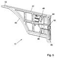
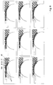
- the conveying system 1 comprises an endless conveyor mat 2 traveling around two divert wheels. In Figs. 1 and 2, only a part of the conveyor mat 2 is visible, adjacent the "end" of the conveyor mat 2 at the location where the conveyor mat 2 travels around a divert wheel 5.
- the conveyor mat 2 comprises a number of rows of plastic modules 4, succeeding each other in a conveying direction 3 and extending transversely to the conveying direction. In Fig. 1, of each row, only one module 4 is shown. In conveying direction, the modules 4 each have a front side 6 and a rear side 7. At their front and rear side 6, 7, the modules 4 are each provided with hinge loops 8.
- the hinge loops 8 of modules 4 succeeding each other in conveying direction 3 cooperate and are coupled by means of hinge pins 9 extending transversely to the conveying direction 3.
- the hinge pins 9 extend transversely to the conveying direction 3 throughout the width of the conveyor mat 4 and are preferably manufactured from plastic.
- the top faces 10 of the modules together constitute a conveying face 11.
- the conveyor mat 2 is built up from rows of modules 4 whose lateral sides 12 abut against each other, while the modules 4 of rows that succeed each other in conveying direction 3 are staggered relative to each other, as in a brickstone pattern.
- the modules 4 are each provided with through openings 13 extending substantially transversely to the conveying face 11. It is observed that "openings 13 extending substantially transversely to the conveying face 11" should also be understood to include openings extending obliquely from the top face 10 to the bottom side 37 of the module 4.
- the modules 4 have a substantially flat top face 10 in which grooves 14 extending in conveying direction 3 are provided.
- the modules 4 are coupled in such a manner that the conveying face 11 is substantially flat and comprises a number of substantially straight slots 15 which extend in conveying direction 3 over the length of the conveyor mat 2 and which have substantially blending sidewalls, formed by the blending sidewalls 29, 30 of the grooves 14 of successive modules 4.
- the conveying system 1 further comprises a slide-over device 16 arranged adjacent the divert wheel 5, for transferring, from the conveying face 11, products which are conveyed by the conveyor mat 2 in the conveying direction 3 to the divert wheel 5.
- the slide-over device 16 comprises a number of substantially flat support bodies 17, each carrying a finger 18 at one end thereof and comprising, at an opposite end, a cylindrical fastening member 19.
- the support bodies 17 are attached in fastening openings 21 in the mounting block 20 in such a manner that their respective fingers 18 each cooperate with one of the slots 15, while between the support bodies 17, an interspace 28 is present.
- the operation of the conveying system is as follows. Products placed on the conveying face 11 of the conveyor mat 2 are displaced in the conveying direction 3 by driving the divert wheel 5 in the direction of the arrow 22. As a result, the projections 23, 24 provided on the outer circumference 25 of the divert wheel 5 engage the modules 4 in the chambers 26. At the location of the divert wheel 5, the modules 4 of the conveyor mat 2 first follow the outer circumference 25 of the divert wheel 5 over about 180° and subsequently follow the return side of their endless path. At the divert wheel 5, the products are transferred away from the conveying face 11, via the slide-over device 16.
- the fingers 18 of the slide-over device 16 project into the slots 15, preferably to a position above or beyond the center line of the divert wheel 5, causing the products which lead in conveying direction 3 to be transferred from the conveying face 11 by the following products, and to be pushed thereby, via the fingers 18, onto the top side 27 of the support bodies 17, in the direction of the mounting block 20.
- the products are further discharged in a generally known manner.
- the products can be placed on the conveying face 11 by means of a slide-over device 17 arranged adjacent the first divert wheel (not shown), of which slide-over device the fingers 18 project in conveying direction 3 into the slots 15. To that end, the products are transferred, by products that follow in conveying direction, over the top sides 27 of the support bodies 17 and via the fingers 18, to the conveying face 11, while dirt, etc. falls into the spaces 28 between the support bodies 17.
- a support body 17 whose finger 18 is damaged or which itself is damaged, can be replaced as a loose unit by removing the support body 17 from the mounting block 20 in a manner which will be explained in more detail in the discussion of the mounting block 20.
- the bases 31 of the grooves 14 are curved in conveying direction such that when they travel around, they substantially blend, the risk of damage to the fingers caused by glass fragments that, during travel, get stuck between the bases 31 and the fingers 18, is also small.
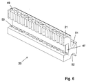
- a module 4 is shown therein.
- the top face 10 of the module 4 is substantially flat, allowing products to stand in a stable manner on the parts of the top face which are located between the grooves 14.
- the grooves 14 each have two sidewalls 29, 30 which are connected via a base 31, so that the chance of fragments falling through the module 4 is reduced.
- the grooves 4 Transversely to the conveying direction, the grooves 4 have a trapezoidal section, which facilitates the cooperation with a finger 18.
- the base 31 of the grooves 14 is at least partially curved with a radius 32 such that when the conveyor mat 2 travels around a divert wheel 5, the slot 15 at that location substantially forms a circular arc with the axis of the divert wheel 5 as center (Fig. 2).
- the section of the grooves 14 transverse to the conveying direction 3 adjacent the front side 6 and the rear side 7 of the module 4 is greater than adjacent the center 33 of the module 4, to facilitate the insertion of the finger 18 into the groove 14.
- the through openings 13 are designed as round holes provided both in the top face 10 of the module 4 and in the base 31 of the grooves 14 provided in the top face 10.
- the through openings 13 In a direction parallel to the conveying face, the through openings 13 have a greatest dimension of less than 15 mm, preferably less than 10 mm, in particular less than 7 mm. It is thus provided that the chance of glass fragments getting stuck in the through openings is reduced.
- the module 4 has its front side 6 and rear side 7 provided with an equal number of hinge loops 8.
- the hinge loops 8 are spaced apart a distance which is substantially equal to the width of a hinge loop 9, and at the front side 6 and rear side 7 of the module 4 they are staggered relative to each other by the width of one hinge loop. Consequently, particularly the shortening of the conveyor mat requires the removal of minimally only one row of modules 4. It is observed that modules 4 whose hinge loops 8 are not staggered relative to each other and/or which have an unequal number of hinge loops 8 at the front side 6 and the rear side 7, are also possible within the framework of the claims.
- the hinge loops 8 are each provided with a fillet 34 touching the top face 10 of the module horizontally, with a radius of a constant magnitude, extending outwards from the center line of the hinge pins 9, parallel to the conveying direction 3, while the spaces between the hinge loops 8 are provided with a recess 35 shaped to correspond with the fillet 34.
- the conveyor mat 2 also has a flat conveying face 11 at the location of the transitions between the rows of modules 4.
- glass grit from the top side 10 is prevented from getting stuck in the space between the modules 4.
- the hinge loops 8 of the modules 4 each have a hinge hole 36 for accommodating a hinge pin 9.
- the center lines of the hinge holes 36 are located at less than half the height of the module 4, i.e. closer to the bottom side 37 than to the top face 10, to prevent the action of glass grit from the bottom side.
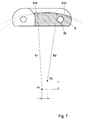
- a support body 17 is shown therein, carrying a finger 18.
- the support body 17 is preferably manufactured from plastic.
- the support body 17 comprises a fastening member 19.
- the support body 17 comprises a curved side 43 cooperating with the curvature of the slot 15 in the conveyor mat 2 at the location of the divert wheel 5 (Fig. 2).
- the section of the finger 18 and the curved side 43 transverse to the conveying direction 3 is designed to correspond to the groove 14, and is in particular trapezoidal, so that the finger 18 and the curved side 43 protect the slot 15 against the intrusion of glass.
- the support body 17 has a flat top side 27 for transferring products from the conveying face 11 in the direction of the mounting block 20.
- the fastening member 19 has at its top side 44 a greater diameter than at the bottom side 45, which will be discussed in more detail in the discussion of the mounting block.
- the support body 17 further comprises a snap finger 46 for cooperation with a corresponding recess 47 in the mounting block 20.
- the snap finger 46 comprises a cover 48 which protects the snap finger 46 from glass fragments and the like falling thereon, and which enables blocking the snap finger 46 in a depressed condition with a screw driver so as to facilitate the assembly/disassembly of the support body 17 on the mounting block 20.
- a mounting block 20 is shown therein, having a number of parallel fastening openings 21 spaced apart in transverse direction of the mounting block 20, comprising an upper row of holes 49 whose diameter is stepped from large to small over the longitudinal direction thereof, a recess 47 and a lower row of holes 50.
- a number of mounting blocks 20 are placed side by side, transverse to the conveying direction 3.
- the mounting block 20 is preferably manufactured from plastic.
- the fastening member 19 is passed through one of the holes of the upper row of holes 49, until the bottom side 45 of the fastening member 19 is located in a corresponding hole of the lower row of holes 50.
- the snap finger 46 rebounds to lock the fastening member 19 through cooperation with the recess 47. Disassembly proceeds in the reverse order.
- the snap finger 46 with a bevel whereby, during insertion, the snap finger is folded in through contact with an edge of the mounting block 20. In that case, the use of a bar during assembly is not necessary.
- the support bodies 17 After assembly of the support bodies 17 to the block 20, the support bodies 17 extend substantially parallel with mutual interspaces 28, and they each have their finger 28 projecting from the slide-over device 16 into a slot 15, against the conveying direction 3.
- the upper part 44 of the fastening member 19 By giving the upper part 44 of the fastening member 19 a larger diameter than the lower part 45, it is provided that the upper part of the fastening member 19 contains sufficient material to take up forces in the conveying direction 3.
- the upper row of holes 49 so that in mounting direction, they have a decreasing, preferably stepped, diameter, the material in transverse direction of the mounting block 20 between the holes 49, 50 moreover has sufficient strength to enable shortening the mounting block 20 in transverse direction between the holes 49, 50.
- the material next to a hole 49 adjacent the edge is sufficiently firm to support the support body 17 without bending outwards, which is not the case if the diameter is large throughout the length of the holes 49.
- the mounting block 20 is further provided with two opposite slots 51, 52, extending transversely to the conveying direction 3, whereby the mounting block 20 can be mounted on a frame 53. Due to the temperature in the pasteurizer, the conveyor mat 2 will expand, for instance by 10 mm per meter at a temperature rise of 60°C.
- the slots 51, 52 have the advantage that upon expansion of the conveyor mat 2, the mounting block 20 can slide transversely to the conveying direction 3.
- the slots 51, 52 also permit expansion of the mounting block 20 relative to the frame 53, due to heating, without warping of the mounting block 20.
- play of the conveyor mat 2 transverse to the conveying direction 3 due to small differences in the width of the hinge loops 8 and the space between the hinge loops of a module 4, can be taken up as well.
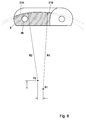
- a part 31A of the base 31 extending over the hinge loop 8 is curved with a radius of curvature R2 which, compared with the radius of curvature R1 of a further part of the base 31B, is smaller and has a center of curvature P2 which is located closer to the hinge hole 36 of the hinge loop 8 than the center of curvature P1 of the other part 31B of the base 31.
- the parts 31A, 31B of the base substantially blend with respect to each other. It is observed that the base 31 may comprise a plurality of curved parts.
- a blending base 31 can be formed relatively quickly through the use of the part 31B that is curved more strongly, as a result of which the change of damage to the finger 18 caused by glass fragments stuck between the successive modules 4 and the finger 18 can be reduced.
- the support body 17 and/or the fingers 18 are provided with an edge 43 curved such that during traveling around, a widening gap S is formed between the base 31 and the finger 18. This permits fragments that have slipped under a first part 18A of the finger 18 to travel around along with a slight chance of damage, and to be subsequently discharged.
Landscapes
- Engineering & Computer Science (AREA)
- Mechanical Engineering (AREA)
- Chain Conveyers (AREA)
- Belt Conveyors (AREA)
- Pivots And Pivotal Connections (AREA)
- Packaging Of Annular Or Rod-Shaped Articles, Wearing Apparel, Cassettes, Or The Like (AREA)
- Structure Of Belt Conveyors (AREA)
- Handcart (AREA)
Applications Claiming Priority (2)
| Application Number | Priority Date | Filing Date | Title |
|---|---|---|---|
| NL1008069 | 1998-01-19 | ||
| NL1008069A NL1008069C2 (nl) | 1998-01-19 | 1998-01-19 | Transportmat alsmede systeem voor het transporteren van producten. |
Publications (2)
| Publication Number | Publication Date |
|---|---|
| EP0930247A1 true EP0930247A1 (fr) | 1999-07-21 |
| EP0930247B1 EP0930247B1 (fr) | 2002-06-12 |
Family
ID=19766375
Family Applications (1)
| Application Number | Title | Priority Date | Filing Date |
|---|---|---|---|
| EP99200150A Expired - Lifetime EP0930247B1 (fr) | 1998-01-19 | 1999-01-18 | Module et tapis de transport et système pour transporter des produits |
Country Status (14)
| Country | Link |
|---|---|
| US (1) | US6193056B1 (fr) |
| EP (1) | EP0930247B1 (fr) |
| JP (1) | JPH11286306A (fr) |
| KR (1) | KR100537283B1 (fr) |
| AR (1) | AR014428A1 (fr) |
| AU (1) | AU746834B2 (fr) |
| BR (1) | BR9900102A (fr) |
| CA (1) | CA2257480C (fr) |
| DE (1) | DE69901732T2 (fr) |
| DK (1) | DK0930247T3 (fr) |
| ES (1) | ES2178341T3 (fr) |
| NL (1) | NL1008069C2 (fr) |
| TW (1) | TW401369B (fr) |
| ZA (1) | ZA99315B (fr) |
Cited By (4)
| Publication number | Priority date | Publication date | Assignee | Title |
|---|---|---|---|---|
| EP1647515A1 (fr) * | 2004-10-13 | 2006-04-19 | Laitram, L.L.C. | Bande transporteuse antidérapant modulaire en matière plastique |
| NL1030625C2 (nl) * | 2005-12-08 | 2007-06-11 | Rexnord Flattop Europe Bv | Modulaire transportmat en transportmatmodule. |
| NL1034337C2 (nl) * | 2007-09-05 | 2009-03-09 | Rexnord Flattop Europe Bv | Module voor een transportmat en modulaire transportmat. |
| NL2002344C2 (en) * | 2008-12-18 | 2010-06-21 | Rexnord Flattop Europe Bv | Conveyor chain module, conveyor chain, conveyor and conveyor system. |
Families Citing this family (13)
| Publication number | Priority date | Publication date | Assignee | Title |
|---|---|---|---|---|
| US6247582B1 (en) * | 1998-12-21 | 2001-06-19 | Rexnord Corporation | Fiber filled chain link for a modular conveyer chain |
| DE19958709C2 (de) * | 1999-12-06 | 2001-10-25 | Kone Corp | Verfahren und Einrichtung zur Reduzierung des Polygoneffektes im Umlenkbereich von Personenförderanlagen |
| WO2002088015A1 (fr) * | 2001-04-27 | 2002-11-07 | Kone Corporation | Procede et dispositif pour reduire l'effet polygone dans la zone de renvoi de systemes de transport de passagers |
| NL1028011C2 (nl) * | 2005-01-12 | 2006-07-13 | Twentebelt B V | Transportband. |
| ES2300225B1 (es) | 2007-11-07 | 2009-08-24 | Thyssenkrupp Elevator (Es/Pbb)Ltd | Pasillo movil. |
| US8905228B2 (en) * | 2013-02-04 | 2014-12-09 | Laitram, L.L.C. | Self-supporting conveyor belt |
| MX393875B (es) * | 2015-02-23 | 2025-03-24 | Span Tech Llc | Transportador de eslabones modulares con caracteristicas para mejorar la transportacion eficaz de articulos. |
| US10543987B2 (en) * | 2016-01-19 | 2020-01-28 | Laitram, L.L.C. | Conveyor belt and module with skewed air-flow passages |
| JP7629872B2 (ja) * | 2019-06-05 | 2025-02-14 | レイトラム,エル.エル.シー. | 滑らかに直径を減少する自動スタッキング式スパイラルベルトコンベヤ |
| CN110817273B (zh) * | 2019-11-19 | 2024-07-16 | 江阴东邦钢球机械有限公司 | 一种消声冷却输送机 |
| CN111891658B (zh) * | 2020-07-23 | 2024-07-12 | 郑州市顺意科技有限公司 | 一种安瓿瓶链条输送装置 |
| CN113879766B (zh) * | 2021-10-27 | 2024-07-09 | 中邮科技股份有限公司 | 一种细辊筒输送机 |
| CN116729891B (zh) * | 2023-06-27 | 2025-11-14 | 宁波得通电子塑料有限公司 | 一种模块链组件、传送带及设计方法 |
Citations (3)
| Publication number | Priority date | Publication date | Assignee | Title |
|---|---|---|---|---|
| US4051949A (en) * | 1976-05-17 | 1977-10-04 | The Laitram Corporation | Conveyor system |
| GB2138376A (en) * | 1983-04-22 | 1984-10-24 | Tillotson V | Conveyor chains |
| DE9212554U1 (de) * | 1991-09-19 | 1993-01-07 | Regina Sud S.P.A., Borgo S. Michele | Modulares Abschlußelement für Förderer |
Family Cites Families (6)
| Publication number | Priority date | Publication date | Assignee | Title |
|---|---|---|---|---|
| US2911091A (en) * | 1955-04-07 | 1959-11-03 | Chain Belt Co | Plastic flat top conveyer |
| US3628834A (en) * | 1969-09-03 | 1971-12-21 | Baychem Corp | Link members and endless chains especially for tracked vehicles |
| US3774752A (en) * | 1971-11-16 | 1973-11-27 | G Harvey | Endless band conveyors |
| US4438838A (en) * | 1981-05-01 | 1984-03-27 | Rexnord Inc. | Conveyor chain for use with fingered transfer plate |
| AU639139B2 (en) * | 1990-10-26 | 1993-07-15 | Rexnord Corporation | Straight running conveyor chain for use with fingered transfer plate |
| AU7676394A (en) * | 1993-08-26 | 1995-03-21 | Kvp Systems, Inc. | Transfer method for plastic conveyor belts |
-
1998
- 1998-01-19 NL NL1008069A patent/NL1008069C2/nl not_active IP Right Cessation
-
1999
- 1999-01-18 DK DK99200150T patent/DK0930247T3/da active
- 1999-01-18 ZA ZA9900315A patent/ZA99315B/xx unknown
- 1999-01-18 AU AU12142/99A patent/AU746834B2/en not_active Ceased
- 1999-01-18 DE DE69901732T patent/DE69901732T2/de not_active Expired - Lifetime
- 1999-01-18 CA CA002257480A patent/CA2257480C/fr not_active Expired - Fee Related
- 1999-01-18 ES ES99200150T patent/ES2178341T3/es not_active Expired - Lifetime
- 1999-01-18 EP EP99200150A patent/EP0930247B1/fr not_active Expired - Lifetime
- 1999-01-19 US US09/233,866 patent/US6193056B1/en not_active Expired - Lifetime
- 1999-01-19 KR KR10-1999-0001402A patent/KR100537283B1/ko not_active Expired - Fee Related
- 1999-01-19 JP JP11010566A patent/JPH11286306A/ja active Pending
- 1999-01-19 TW TW088100743A patent/TW401369B/zh active
- 1999-01-19 BR BR9900102-0A patent/BR9900102A/pt not_active Application Discontinuation
- 1999-01-19 AR ARP990100195A patent/AR014428A1/es unknown
Patent Citations (3)
| Publication number | Priority date | Publication date | Assignee | Title |
|---|---|---|---|---|
| US4051949A (en) * | 1976-05-17 | 1977-10-04 | The Laitram Corporation | Conveyor system |
| GB2138376A (en) * | 1983-04-22 | 1984-10-24 | Tillotson V | Conveyor chains |
| DE9212554U1 (de) * | 1991-09-19 | 1993-01-07 | Regina Sud S.P.A., Borgo S. Michele | Modulares Abschlußelement für Förderer |
Cited By (7)
| Publication number | Priority date | Publication date | Assignee | Title |
|---|---|---|---|---|
| EP1647515A1 (fr) * | 2004-10-13 | 2006-04-19 | Laitram, L.L.C. | Bande transporteuse antidérapant modulaire en matière plastique |
| NL1030625C2 (nl) * | 2005-12-08 | 2007-06-11 | Rexnord Flattop Europe Bv | Modulaire transportmat en transportmatmodule. |
| WO2007067047A1 (fr) * | 2005-12-08 | 2007-06-14 | Rexnord Flattop Europe B.V. | Bande transporteuse modulaire et module de bande transporteuse |
| US8430235B2 (en) | 2005-12-08 | 2013-04-30 | Rexnord Flattop Europe B.V. | Modular conveyor mat and conveyor mat module |
| NL1034337C2 (nl) * | 2007-09-05 | 2009-03-09 | Rexnord Flattop Europe Bv | Module voor een transportmat en modulaire transportmat. |
| WO2009031895A1 (fr) * | 2007-09-05 | 2009-03-12 | Rexnord Flattop Europe B.V. | Module pour tapis transporteur et tapis transporteur modulaire |
| NL2002344C2 (en) * | 2008-12-18 | 2010-06-21 | Rexnord Flattop Europe Bv | Conveyor chain module, conveyor chain, conveyor and conveyor system. |
Also Published As
| Publication number | Publication date |
|---|---|
| US6193056B1 (en) | 2001-02-27 |
| DK0930247T3 (da) | 2002-09-23 |
| NL1008069C2 (nl) | 1999-07-20 |
| CA2257480C (fr) | 2007-11-20 |
| BR9900102A (pt) | 2000-01-04 |
| DE69901732D1 (de) | 2002-07-18 |
| DE69901732T2 (de) | 2004-04-01 |
| KR19990067975A (ko) | 1999-08-25 |
| EP0930247B1 (fr) | 2002-06-12 |
| CA2257480A1 (fr) | 1999-07-19 |
| ZA99315B (en) | 1999-07-19 |
| JPH11286306A (ja) | 1999-10-19 |
| AR014428A1 (es) | 2001-02-28 |
| TW401369B (en) | 2000-08-11 |
| ES2178341T3 (es) | 2002-12-16 |
| KR100537283B1 (ko) | 2005-12-16 |
| AU746834B2 (en) | 2002-05-02 |
| AU1214299A (en) | 1999-08-05 |
Similar Documents
| Publication | Publication Date | Title |
|---|---|---|
| EP0930247B1 (fr) | Module et tapis de transport et système pour transporter des produits | |
| EP0930254B1 (fr) | Système pour convoyer des produits, et dispositif de transfert | |
| CN101394736B (zh) | 用于对碰撞敏感的产品的输送装置 | |
| US7448490B2 (en) | Conveying system with a slide-over device between two belt conveyors, slide-over device and intermediate element with a slide-over surface | |
| US5706934A (en) | Modular solid top plastic conveyor belt | |
| US20030015406A1 (en) | Snap-on side guards | |
| EP0598453A1 (fr) | Tapis de transport composé de modules synthétiques et modules pour un tel tapis de transport | |
| EP0427337B1 (fr) | Convoyeur pour une unité de traitement | |
| MX2010007933A (es) | Transportador acondicionado con proteccion lateral, y elemento de proteccion lateral. | |
| US20020195321A1 (en) | Flush Grid belt module | |
| EP3962839B1 (fr) | Courroie de convoyeur modulaire ayant des surfaces d'entrainement alternatives | |
| MXPA99000731A (en) | Transportation mesh and system to transport produce | |
| MXPA99000750A (en) | Conveying system for conveying products, and slide-over device |
Legal Events
| Date | Code | Title | Description |
|---|---|---|---|
| PUAI | Public reference made under article 153(3) epc to a published international application that has entered the european phase |
Free format text: ORIGINAL CODE: 0009012 |
|
| AK | Designated contracting states |
Kind code of ref document: A1 Designated state(s): DE DK ES FR GB IT NL |
|
| AX | Request for extension of the european patent |
Free format text: AL;LT;LV;MK;RO;SI |
|
| 17P | Request for examination filed |
Effective date: 19991109 |
|
| AKX | Designation fees paid |
Free format text: DE DK ES FR GB IT NL |
|
| 17Q | First examination report despatched |
Effective date: 20000828 |
|
| GRAG | Despatch of communication of intention to grant |
Free format text: ORIGINAL CODE: EPIDOS AGRA |
|
| RTI1 | Title (correction) |
Free format text: CONVEYOR MODULE AND MAT AND SYSTEM FOR CONVEYING PRODUCTS |
|
| GRAG | Despatch of communication of intention to grant |
Free format text: ORIGINAL CODE: EPIDOS AGRA |
|
| GRAH | Despatch of communication of intention to grant a patent |
Free format text: ORIGINAL CODE: EPIDOS IGRA |
|
| GRAH | Despatch of communication of intention to grant a patent |
Free format text: ORIGINAL CODE: EPIDOS IGRA |
|
| GRAA | (expected) grant |
Free format text: ORIGINAL CODE: 0009210 |
|
| AK | Designated contracting states |
Kind code of ref document: B1 Designated state(s): DE DK ES FR GB IT NL |
|
| REG | Reference to a national code |
Ref country code: GB Ref legal event code: FG4D |
|
| REF | Corresponds to: |
Ref document number: 69901732 Country of ref document: DE Date of ref document: 20020718 |
|
| REG | Reference to a national code |
Ref country code: DK Ref legal event code: T3 |
|
| ET | Fr: translation filed | ||
| REG | Reference to a national code |
Ref country code: ES Ref legal event code: FG2A Ref document number: 2178341 Country of ref document: ES Kind code of ref document: T3 |
|
| PLBE | No opposition filed within time limit |
Free format text: ORIGINAL CODE: 0009261 |
|
| STAA | Information on the status of an ep patent application or granted ep patent |
Free format text: STATUS: NO OPPOSITION FILED WITHIN TIME LIMIT |
|
| 26N | No opposition filed |
Effective date: 20030313 |
|
| PGFP | Annual fee paid to national office [announced via postgrant information from national office to epo] |
Ref country code: ES Payment date: 20090114 Year of fee payment: 11 Ref country code: DK Payment date: 20090123 Year of fee payment: 11 |
|
| PGFP | Annual fee paid to national office [announced via postgrant information from national office to epo] |
Ref country code: GB Payment date: 20090114 Year of fee payment: 11 |
|
| PGFP | Annual fee paid to national office [announced via postgrant information from national office to epo] |
Ref country code: FR Payment date: 20090114 Year of fee payment: 11 |
|
| REG | Reference to a national code |
Ref country code: DK Ref legal event code: EBP |
|
| GBPC | Gb: european patent ceased through non-payment of renewal fee |
Effective date: 20100118 |
|
| REG | Reference to a national code |
Ref country code: FR Ref legal event code: ST Effective date: 20100930 |
|
| PG25 | Lapsed in a contracting state [announced via postgrant information from national office to epo] |
Ref country code: FR Free format text: LAPSE BECAUSE OF NON-PAYMENT OF DUE FEES Effective date: 20100201 |
|
| PG25 | Lapsed in a contracting state [announced via postgrant information from national office to epo] |
Ref country code: GB Free format text: LAPSE BECAUSE OF NON-PAYMENT OF DUE FEES Effective date: 20100118 |
|
| PG25 | Lapsed in a contracting state [announced via postgrant information from national office to epo] |
Ref country code: DK Free format text: LAPSE BECAUSE OF NON-PAYMENT OF DUE FEES Effective date: 20100131 |
|
| REG | Reference to a national code |
Ref country code: ES Ref legal event code: FD2A Effective date: 20110408 |
|
| PG25 | Lapsed in a contracting state [announced via postgrant information from national office to epo] |
Ref country code: ES Free format text: LAPSE BECAUSE OF NON-PAYMENT OF DUE FEES Effective date: 20110324 |
|
| PG25 | Lapsed in a contracting state [announced via postgrant information from national office to epo] |
Ref country code: ES Free format text: LAPSE BECAUSE OF NON-PAYMENT OF DUE FEES Effective date: 20100119 |
|
| PGFP | Annual fee paid to national office [announced via postgrant information from national office to epo] |
Ref country code: DE Payment date: 20140122 Year of fee payment: 16 Ref country code: NL Payment date: 20140115 Year of fee payment: 16 |
|
| PGFP | Annual fee paid to national office [announced via postgrant information from national office to epo] |
Ref country code: IT Payment date: 20140131 Year of fee payment: 16 |
|
| REG | Reference to a national code |
Ref country code: DE Ref legal event code: R119 Ref document number: 69901732 Country of ref document: DE |
|
| REG | Reference to a national code |
Ref country code: NL Ref legal event code: V1 Effective date: 20150801 |
|
| PG25 | Lapsed in a contracting state [announced via postgrant information from national office to epo] |
Ref country code: NL Free format text: LAPSE BECAUSE OF NON-PAYMENT OF DUE FEES Effective date: 20150801 |
|
| PG25 | Lapsed in a contracting state [announced via postgrant information from national office to epo] |
Ref country code: DE Free format text: LAPSE BECAUSE OF FAILURE TO SUBMIT A TRANSLATION OF THE DESCRIPTION OR TO PAY THE FEE WITHIN THE PRESCRIBED TIME-LIMIT Effective date: 20150801 |
|
| PG25 | Lapsed in a contracting state [announced via postgrant information from national office to epo] |
Ref country code: IT Free format text: LAPSE BECAUSE OF NON-PAYMENT OF DUE FEES Effective date: 20150118 |