EP0930427A2 - Moteur à combustion interne et procédé de préparation du mélange - Google Patents
Moteur à combustion interne et procédé de préparation du mélange Download PDFInfo
- Publication number
- EP0930427A2 EP0930427A2 EP99100595A EP99100595A EP0930427A2 EP 0930427 A2 EP0930427 A2 EP 0930427A2 EP 99100595 A EP99100595 A EP 99100595A EP 99100595 A EP99100595 A EP 99100595A EP 0930427 A2 EP0930427 A2 EP 0930427A2
- Authority
- EP
- European Patent Office
- Prior art keywords
- internal combustion
- combustion engine
- engine according
- piston
- combustion chamber
- Prior art date
- Legal status (The legal status is an assumption and is not a legal conclusion. Google has not performed a legal analysis and makes no representation as to the accuracy of the status listed.)
- Granted
Links
Images



Classifications
-
- F—MECHANICAL ENGINEERING; LIGHTING; HEATING; WEAPONS; BLASTING
- F02—COMBUSTION ENGINES; HOT-GAS OR COMBUSTION-PRODUCT ENGINE PLANTS
- F02F—CYLINDERS, PISTONS OR CASINGS, FOR COMBUSTION ENGINES; ARRANGEMENTS OF SEALINGS IN COMBUSTION ENGINES
- F02F1/00—Cylinders; Cylinder heads
- F02F1/24—Cylinder heads
- F02F1/42—Shape or arrangement of intake or exhaust channels in cylinder heads
- F02F1/4214—Shape or arrangement of intake or exhaust channels in cylinder heads specially adapted for four or more valves per cylinder
-
- F—MECHANICAL ENGINEERING; LIGHTING; HEATING; WEAPONS; BLASTING
- F02—COMBUSTION ENGINES; HOT-GAS OR COMBUSTION-PRODUCT ENGINE PLANTS
- F02B—INTERNAL-COMBUSTION PISTON ENGINES; COMBUSTION ENGINES IN GENERAL
- F02B23/00—Other engines characterised by special shape or construction of combustion chambers to improve operation
- F02B23/08—Other engines characterised by special shape or construction of combustion chambers to improve operation with positive ignition
- F02B23/10—Other engines characterised by special shape or construction of combustion chambers to improve operation with positive ignition with separate admission of air and fuel into cylinder
- F02B23/104—Other engines characterised by special shape or construction of combustion chambers to improve operation with positive ignition with separate admission of air and fuel into cylinder the injector being placed on a side position of the cylinder
-
- F—MECHANICAL ENGINEERING; LIGHTING; HEATING; WEAPONS; BLASTING
- F02—COMBUSTION ENGINES; HOT-GAS OR COMBUSTION-PRODUCT ENGINE PLANTS
- F02B—INTERNAL-COMBUSTION PISTON ENGINES; COMBUSTION ENGINES IN GENERAL
- F02B31/00—Modifying induction systems for imparting a rotation to the charge in the cylinder
- F02B31/08—Modifying induction systems for imparting a rotation to the charge in the cylinder having multiple air inlets
- F02B31/085—Modifying induction systems for imparting a rotation to the charge in the cylinder having multiple air inlets having two inlet valves
-
- F—MECHANICAL ENGINEERING; LIGHTING; HEATING; WEAPONS; BLASTING
- F02—COMBUSTION ENGINES; HOT-GAS OR COMBUSTION-PRODUCT ENGINE PLANTS
- F02B—INTERNAL-COMBUSTION PISTON ENGINES; COMBUSTION ENGINES IN GENERAL
- F02B23/00—Other engines characterised by special shape or construction of combustion chambers to improve operation
- F02B23/08—Other engines characterised by special shape or construction of combustion chambers to improve operation with positive ignition
- F02B23/10—Other engines characterised by special shape or construction of combustion chambers to improve operation with positive ignition with separate admission of air and fuel into cylinder
- F02B2023/106—Tumble flow, i.e. the axis of rotation of the main charge flow motion is horizontal
-
- F—MECHANICAL ENGINEERING; LIGHTING; HEATING; WEAPONS; BLASTING
- F02—COMBUSTION ENGINES; HOT-GAS OR COMBUSTION-PRODUCT ENGINE PLANTS
- F02B—INTERNAL-COMBUSTION PISTON ENGINES; COMBUSTION ENGINES IN GENERAL
- F02B75/00—Other engines
- F02B75/12—Other methods of operation
- F02B2075/125—Direct injection in the combustion chamber for spark ignition engines, i.e. not in pre-combustion chamber
-
- F—MECHANICAL ENGINEERING; LIGHTING; HEATING; WEAPONS; BLASTING
- F02—COMBUSTION ENGINES; HOT-GAS OR COMBUSTION-PRODUCT ENGINE PLANTS
- F02F—CYLINDERS, PISTONS OR CASINGS, FOR COMBUSTION ENGINES; ARRANGEMENTS OF SEALINGS IN COMBUSTION ENGINES
- F02F1/00—Cylinders; Cylinder heads
- F02F1/24—Cylinder heads
- F02F1/242—Arrangement of spark plugs or injectors
-
- F—MECHANICAL ENGINEERING; LIGHTING; HEATING; WEAPONS; BLASTING
- F02—COMBUSTION ENGINES; HOT-GAS OR COMBUSTION-PRODUCT ENGINE PLANTS
- F02F—CYLINDERS, PISTONS OR CASINGS, FOR COMBUSTION ENGINES; ARRANGEMENTS OF SEALINGS IN COMBUSTION ENGINES
- F02F1/00—Cylinders; Cylinder heads
- F02F1/24—Cylinder heads
- F02F2001/241—Cylinder heads specially adapted to pent roof shape of the combustion chamber
-
- F—MECHANICAL ENGINEERING; LIGHTING; HEATING; WEAPONS; BLASTING
- F02—COMBUSTION ENGINES; HOT-GAS OR COMBUSTION-PRODUCT ENGINE PLANTS
- F02F—CYLINDERS, PISTONS OR CASINGS, FOR COMBUSTION ENGINES; ARRANGEMENTS OF SEALINGS IN COMBUSTION ENGINES
- F02F1/00—Cylinders; Cylinder heads
- F02F1/24—Cylinder heads
- F02F2001/244—Arrangement of valve stems in cylinder heads
- F02F2001/245—Arrangement of valve stems in cylinder heads the valve stems being orientated at an angle with the cylinder axis
-
- F—MECHANICAL ENGINEERING; LIGHTING; HEATING; WEAPONS; BLASTING
- F02—COMBUSTION ENGINES; HOT-GAS OR COMBUSTION-PRODUCT ENGINE PLANTS
- F02F—CYLINDERS, PISTONS OR CASINGS, FOR COMBUSTION ENGINES; ARRANGEMENTS OF SEALINGS IN COMBUSTION ENGINES
- F02F3/00—Pistons
- F02F3/26—Pistons having combustion chamber in piston head
-
- Y—GENERAL TAGGING OF NEW TECHNOLOGICAL DEVELOPMENTS; GENERAL TAGGING OF CROSS-SECTIONAL TECHNOLOGIES SPANNING OVER SEVERAL SECTIONS OF THE IPC; TECHNICAL SUBJECTS COVERED BY FORMER USPC CROSS-REFERENCE ART COLLECTIONS [XRACs] AND DIGESTS
- Y02—TECHNOLOGIES OR APPLICATIONS FOR MITIGATION OR ADAPTATION AGAINST CLIMATE CHANGE
- Y02T—CLIMATE CHANGE MITIGATION TECHNOLOGIES RELATED TO TRANSPORTATION
- Y02T10/00—Road transport of goods or passengers
- Y02T10/10—Internal combustion engine [ICE] based vehicles
- Y02T10/12—Improving ICE efficiencies
Definitions
- the present invention relates to an internal combustion engine per cylinder two inlet valves arranged side by side, at least one outlet valve, a substantially coaxial spark plug, an injector and a piston per cylinder.
- the present invention further relates to a method for mixture preparation in an internal combustion engine.
- Such an internal combustion engine is for example from the document US 4,617,896 known.
- this internal combustion engine are within the Intake pipe provided several inlet channels, which are the inlet valves can be assigned, and are partly within these inlet channels Throttle valves provided.
- the cylinder head connected to the intake manifold the engine has one of the intake valves common inlet channel into which an injection valve opens. Because of the design of the inlet channels can be in the common inlet channel before Intake valves a good mixture swirl take place. Is problematic however, that this mixture is not without significant flow losses introduced the inlet valves into the combustion chamber of the internal combustion engine can be.
- this embodiment is for internal combustion engines hardly suitable with direct petrol injection.
- the internal combustion engine has the features of Claim 1 on. So the injector is between the two Inlet valves and the portion adjacent to the two inlet valves arranged in the cylinder wall and the piston has a first and a second combustion chamber trough, the first and the second combustion chamber trough arranged at different distances from the injection valve are.
- the internal combustion engine works due to the arrangement of the injection valve as direct injection, which means that the mixture is only processed in the combustion chamber becomes.
- An improved mixture preparation is obtained by the piston reciprocating in the cylinder in coordination with the previous ones
- a first and a second combustion chamber trough has, wherein the first and the second combustion chamber trough the injection valve are each arranged at different distances.
- the two inlet valves are at a maximum distance from one another.
- the two inlet valves should have a minimum in the closed position Have a distance to the axis of the crankshaft.
- the injection valve can be at an angle of approx. 60 to 80 degrees to the axis of the cylinder can be arranged inclined. This can be between the two Inlet valves and that adjacent to the two inlet valves Section of the cylinder wall arranged injection valve available use the available space in a space-saving manner.
- the injection valve preferably has a bend angle that defines the injection jet distracts. With the help of this bend angle, the direction of the injection jet set so that the injection jet for homogeneous lean operation at a first crankshaft angle range into the tumble flow and for stratified operation in a second crankshaft angle range below the tumble flow in the combustion chamber in the second combustion chamber trough takes place, whereby one in both operating cases optimal mixture preparation takes place.
- the injection valve expediently sprays for homogeneous lean operation during the intake stroke at a crankshaft angle of approx. 440 to 280 degrees before the piston reaches top dead center, fuel into the Cylinder. Because in this way the fuel is approximately in the middle of the Prevailing fresh air flow introduced so that the Fuel and fresh air can be mixed well.
- the injection valve sprays during the compression stroke at a crankshaft angle of approx. 120 to 30 Degrees before the piston reaches top dead center, fuel into the second Combustion chamber bowl of the piston. So a large part of the fuel injected below the tumble-shaped fresh air flow, from the Fresh air flow torn up and finally to the spark plug transported.
- the first combustion bowl serves to guide the tumble-shaped Fresh air flow, while the second combustion chamber trough Stabilization of the stratified charge is formed.
- the two combustion chamber troughs of the piston are each preferably elongated educated. And the first of the two combustion chamber troughs is particularly preferred somewhat smaller and less deep than the second of the two Firebox troughs. Because this characteristic favors that in the stratified Lean operation of the fuel below the tumble-shaped Fresh air flow injected into the second of the two combustion chamber troughs can be.
- the boundary wall of the first combustion bowl can to the side of the intake valves rising steeply and gently tapering to the side of the exhaust valves be formed while the boundary wall of the second combustion chamber trough gently draining to the side of the inlet valves and to the side of the Exhaust valves is designed to rise steeply.
- the gently draining Boundary walls become the entry of the tumble-shaped fresh air flow into the first combustion chamber trough or the injection of the conical Fuel jet in the second combustion chamber recess facilitated. And through that The steeply rising boundary walls become in the further course of the mixture preparation supports the mixing of fresh air and fuel.
- the combustion chamber troughs can be made by means of an essentially straight web be separated from each other.
- the dimensions of the web determine how strong the tumble-shaped fresh air flow and the conical injection jet be mixed in homogeneous lean operation or in stratified Lean operation can be stabilized against each other.
- the web is to the center line of the piston arranged obliquely and in a second embodiment, the web is for Center line of the piston arranged in parallel.
- the web can be in the area below the spark plug with one connecting the two combustion chamber troughs Breakthrough.
- This breakthrough creates an additional one Space for an even stronger mixing of rich and lean gas mixture and ensures a safe ignition. It has proven itself if the breakthrough the height of the web to at least half reduced and the length of the web by about 8-20% of the piston diameter decreased.
- the piston should be advantageous due to the inclination to each other Inlet and outlet valves may be roof-shaped, the roof ridge should run substantially along the center line of the piston.
- the object of the present invention is further achieved by a method for mixture preparation in an internal combustion engine according to claim 17 by creating a complex air flow within the cylinders which is divided into two flow branches is trained.
- the mixture preparation is carried out by means of these two flow branches and thus the efficiency of the internal combustion engine improved considerably.
- the axes of the two tumble-shaped flow branches preferably close of the double surround together at an angle of approx. 0 to +/- 45 degrees on.
- Fuel is used for the homogeneous lean operation of the internal combustion engine injected against the two flow branches and stratified for one Lean operation becomes fuel below one of the two flow branches or below the two flow branches in the second combustion chamber trough injected.
- the injected fuel becomes homogeneous Lean operation well distributed within the combustion chamber and in the stratified Lean operation as a stabilized mixture cloud to the spark plug transported where it can then be ignited.
- FIGS. 1 and 6 equipped two side-by-side inlet valves 1 per cylinder. These inlet valves 1 are not located on one half of one shown cylinder and two side-by-side outlet valves 2 are on the other half of the cylinder.
- the Internal combustion engine has a spark plug 3, which is concentric to the axis of the cylinder is arranged.
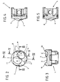
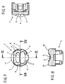
- FIGS. 1 and 6 also show one in the cylinder of FIG Internal combustion engine arranged pistons 5 with two combustion chamber troughs 6, 6 'according to a first and a second embodiment.
- the fresh air flowing into the cylinder through the two inlet valves 1 forms a tumble flow within the combustion chamber. Training the tumble flow is favored when the two inlet valves 1 have a maximum distance from each other and one in the closed position have a minimum distance to the axis of the crankshaft.
- the inlet valves 1 and the outlet valves 2 are closed the spark plug 3 or arranged inclined to the axis of the cylinder.
- the injection valve 4 of the internal combustion engine is also on the axis of the cylinder arranged inclined, the angle of inclination a about 30 to 75 degrees is.
- the injector 4 provided with a bend angle that the injection jet E by about 15 degrees deflects so that the injection jet E depending on the operating state and crankshaft angle into the prevailing flow or into the second combustion chamber trough 6 'is directed.
- the injector comes 4, however, without a bend angle.
- the first embodiment in Figures 1 to 5 are the two combustion chamber troughs 6, 6 'to the center line M. of the piston 5 arranged offset.
- the first combustion chamber trough 6 is also somewhat smaller and less there deep as the second combustion chamber trough 6 '.
- the boundary wall 7 is the first combustion chamber trough 6 steeply rising to the side of the injection valves 1 and to Side of the exhaust valves 2 formed gently tapering, while the boundary wall 7 of the second combustion chamber trough 6 'to the side of the intake valves 1 gently tapering and rising steeply to the side of the exhaust valves 2 is trained.
- the boundary walls 7 formed in this way are special well suited for the tumble-like fresh air flow upwards redirected and the fuel injected into the second combustion chamber recess 6 ' can be.
- the deflection of the tumble flow is also supported through one or two ramps 8 next to the first combustion chamber trough 6, which the steeply rising boundary wall 7 of the second combustion bowl 6 ' are arranged adjacent.
- the two combustion chamber troughs 6, 6 ' are essentially straight by means of one Web 9 separated from each other. According to a further development, this web 9 can in the area below the spark plug 3 with one of the two combustion chamber troughs 6, 6 'connecting breakthrough. This breakthrough creates an additional space below the spark plug 3 for one stronger mixing of the gas mixtures and / or a safe ignition.
- pistons 5 according to the first and the second embodiment of the invention each formed roof-shaped, the ridge 10 in runs essentially along the center line M of the piston 5, which at the same time the dividing line between the inlet side and the outlet side of the piston 5.
- the piston 5 still has some squeezing surfaces 11 that are outside of the two combustion chamber troughs 6, 6 'are arranged.
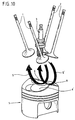
- FIGS. 10 and 11 are used to explain the method for mixture preparation the arrangement again for an internal combustion engine of gas exchange valves 1, 2, spark plug 3 and piston 5 of an internal combustion engine shown in Figure 1 and 6.
- the fuel is counter to the two flow branches S, S ', below the second flow branch S' ( Figure 10) or below the two flow branches S, S '( Figure 11) in the second combustion chamber bowl 6 'of the piston 5 is injected.
Landscapes
- Engineering & Computer Science (AREA)
- Chemical & Material Sciences (AREA)
- Combustion & Propulsion (AREA)
- Mechanical Engineering (AREA)
- General Engineering & Computer Science (AREA)
- Combustion Methods Of Internal-Combustion Engines (AREA)
Applications Claiming Priority (2)
| Application Number | Priority Date | Filing Date | Title |
|---|---|---|---|
| DE19801607 | 1998-01-17 | ||
| DE19801607A DE19801607A1 (de) | 1998-01-17 | 1998-01-17 | Brennkraftmaschine und Verfahren zur Gemischaufbereitung bei einer Brennkraftmaschine |
Publications (3)
| Publication Number | Publication Date |
|---|---|
| EP0930427A2 true EP0930427A2 (fr) | 1999-07-21 |
| EP0930427A3 EP0930427A3 (fr) | 2000-04-05 |
| EP0930427B1 EP0930427B1 (fr) | 2004-08-18 |
Family
ID=7854886
Family Applications (1)
| Application Number | Title | Priority Date | Filing Date |
|---|---|---|---|
| EP99100595A Expired - Lifetime EP0930427B1 (fr) | 1998-01-17 | 1999-01-14 | Moteur à combustion interne et procédé de préparation du mélange |
Country Status (2)
| Country | Link |
|---|---|
| EP (1) | EP0930427B1 (fr) |
| DE (2) | DE19801607A1 (fr) |
Cited By (4)
| Publication number | Priority date | Publication date | Assignee | Title |
|---|---|---|---|---|
| EP1199462A3 (fr) * | 2000-10-20 | 2003-04-23 | Yamaha Hatsudoki Kabushiki Kaisha | Moteur à combustion interne et piston pour un moteur à combustion interne |
| EP1288461A3 (fr) * | 2001-08-24 | 2004-08-04 | Toyota Jidosha Kabushiki Kaisha | Moteur à combustion interne à injection directe et à allumage par étincelle |
| FR2853353A1 (fr) * | 2003-04-04 | 2004-10-08 | Peugeot Citroen Automobiles Sa | Moteur a combustion interne, a essence et a allumage commande |
| FR2861431A1 (fr) * | 2003-10-24 | 2005-04-29 | Renault Sa | Piston pour chambre de combustion a haute vitesse de combustion. |
Families Citing this family (1)
| Publication number | Priority date | Publication date | Assignee | Title |
|---|---|---|---|---|
| DE102006044698B4 (de) * | 2006-09-22 | 2017-08-03 | Bayerische Motoren Werke Aktiengesellschaft | Brennverfahren für eine mittels Kraftstoffdirekteinspritzung und Aufladung betriebene fremdgezündete Hubkolben-Brennkraftmaschine |
Citations (1)
| Publication number | Priority date | Publication date | Assignee | Title |
|---|---|---|---|---|
| US4617896A (en) | 1985-03-14 | 1986-10-21 | Yamaha Hatsudoki Kabushiki Kaisha | Internal combustion engine having three intake valves per cylinder |
Family Cites Families (12)
| Publication number | Priority date | Publication date | Assignee | Title |
|---|---|---|---|---|
| JPS61138816A (ja) * | 1984-12-07 | 1986-06-26 | Toyota Motor Corp | 直噴式内燃機関の燃料蒸発率制御装置 |
| DE4020262A1 (de) * | 1990-06-26 | 1992-01-09 | Daimler Benz Ag | Kolben fuer eine gemischverdichtende brennkraftmaschine |
| JPH05179961A (ja) * | 1991-12-27 | 1993-07-20 | Toyota Motor Corp | 筒内噴射式内燃機関 |
| DE4415073A1 (de) * | 1994-04-29 | 1995-11-02 | Fev Motorentech Gmbh & Co Kg | Hubkolbenmotor mit direkter Kraftstoffeinspritzeinrichtung und Funkenzündung, insbesondere für den Betrieb mit Alkoholkraftstoff |
| KR100266059B1 (ko) * | 1995-03-28 | 2000-10-02 | 나까무라 히로까즈 | 통내분사형내연기관 |
| EP0778403B1 (fr) * | 1995-03-28 | 2000-11-08 | Mitsubishi Jidosha Kogyo Kabushiki Kaisha | Moteur a combustion interne du type a injection dans le cylindre |
| JP3681080B2 (ja) * | 1996-02-09 | 2005-08-10 | 富士重工業株式会社 | 筒内直噴式火花点火エンジンの燃焼室構造 |
| DE19713029C2 (de) * | 1996-04-01 | 2000-02-24 | Avl List Gmbh | Viertakt-Brennkraftmaschine mit Fremdzündung |
| DE19713028C2 (de) * | 1996-04-01 | 2000-02-24 | Avl List Gmbh | Viertakt-Brennkraftmaschine mit Fremdzündung |
| DE19713030C2 (de) * | 1996-04-01 | 2000-02-24 | Avl List Gmbh | Viertakt-Brennkraftmaschine mit Fremdzündung |
| DE19638024A1 (de) * | 1996-09-18 | 1998-03-19 | Bosch Gmbh Robert | Brennkraftmaschine |
| DE19741380C2 (de) * | 1996-09-20 | 2000-12-28 | Fev Motorentech Gmbh | Hubkolbenbrennkraftmaschine mit Kraftstoffdirekteinspritzung über einen einlaßseitig angeordneten Injektor |
-
1998
- 1998-01-17 DE DE19801607A patent/DE19801607A1/de not_active Withdrawn
-
1999
- 1999-01-14 EP EP99100595A patent/EP0930427B1/fr not_active Expired - Lifetime
- 1999-01-14 DE DE59910231T patent/DE59910231D1/de not_active Expired - Lifetime
Patent Citations (1)
| Publication number | Priority date | Publication date | Assignee | Title |
|---|---|---|---|---|
| US4617896A (en) | 1985-03-14 | 1986-10-21 | Yamaha Hatsudoki Kabushiki Kaisha | Internal combustion engine having three intake valves per cylinder |
Cited By (4)
| Publication number | Priority date | Publication date | Assignee | Title |
|---|---|---|---|---|
| EP1199462A3 (fr) * | 2000-10-20 | 2003-04-23 | Yamaha Hatsudoki Kabushiki Kaisha | Moteur à combustion interne et piston pour un moteur à combustion interne |
| EP1288461A3 (fr) * | 2001-08-24 | 2004-08-04 | Toyota Jidosha Kabushiki Kaisha | Moteur à combustion interne à injection directe et à allumage par étincelle |
| FR2853353A1 (fr) * | 2003-04-04 | 2004-10-08 | Peugeot Citroen Automobiles Sa | Moteur a combustion interne, a essence et a allumage commande |
| FR2861431A1 (fr) * | 2003-10-24 | 2005-04-29 | Renault Sa | Piston pour chambre de combustion a haute vitesse de combustion. |
Also Published As
| Publication number | Publication date |
|---|---|
| EP0930427B1 (fr) | 2004-08-18 |
| DE59910231D1 (de) | 2004-09-23 |
| EP0930427A3 (fr) | 2000-04-05 |
| DE19801607A1 (de) | 1999-07-22 |
Similar Documents
| Publication | Publication Date | Title |
|---|---|---|
| DE3690387C2 (de) | Verfahren zum Betreiben einer fremdgezündeten Zweitakt-Brennkraftmaschine | |
| DE69615130T2 (de) | Brennkraftmaschine des direkteinspritzung | |
| DE19804161C2 (de) | Viertakt-Brennkraftmaschine | |
| EP1060330B1 (fr) | Moteur a combustion interne a injection directe | |
| DE102004058244B4 (de) | Direkteinspritzmotor | |
| DE69108994T2 (de) | Zweitaktbrennkraftmaschine. | |
| DE3016139A1 (de) | Einsatz zum bilden einer vorkammer im zylinderkopf einer dieselmaschine | |
| DE19741380C2 (de) | Hubkolbenbrennkraftmaschine mit Kraftstoffdirekteinspritzung über einen einlaßseitig angeordneten Injektor | |
| DE3718083C2 (fr) | ||
| EP0897052B1 (fr) | Moteur à combustion interne à allumage par étincelle | |
| DE10354682B4 (de) | Hubkolbenbrennkraftmaschine mit Kraftstoffdirekteinspritzung über einen einlaßseitig angeordneten Injektor | |
| DE3808672A1 (de) | Verbrennungsmaschine | |
| DE2839051A1 (de) | Gegenkolben-zweitaktbrennkraftmaschine mit gleichstromspuelung | |
| DE19846257A1 (de) | Kraftstoffeinspritzeinrichtung für eine Brennkraftmaschine | |
| EP0930427B1 (fr) | Moteur à combustion interne et procédé de préparation du mélange | |
| DE10354827A1 (de) | Brennstoffeinspritzsystem | |
| EP1272748A1 (fr) | Moteur a combustion interne a pistons alternatifs avec injection directe du carburant par un injecteur place cote admission | |
| DE2508081C3 (de) | Brennkraftmaschine mit Haupt- und Zusatzbrennkammer | |
| DE19820085B4 (de) | Direkteinspritzende Brennkraftmaschine | |
| DE2454813A1 (de) | Fackelgezuendeter hubkolbenverbrennungsmotor | |
| EP1135583B1 (fr) | Moteur a combustion interne a injection directe | |
| EP0907825B1 (fr) | Moteur deux temps a allumage par etincelle, a compression du melange et a injection de carburant | |
| DE10323000B4 (de) | Verfahren sowie Kolben-Zylindereinheit zum Erzeugen eines brennfähigen Kraftstoff-Gasgemisches in einem Brennraum einer Hubkolbenbrennkraftmaschine | |
| DE19730842A1 (de) | Brennkraftmaschine | |
| DE69806480T2 (de) | Brennkraftmaschine mit fremdzündung |
Legal Events
| Date | Code | Title | Description |
|---|---|---|---|
| PUAI | Public reference made under article 153(3) epc to a published international application that has entered the european phase |
Free format text: ORIGINAL CODE: 0009012 |
|
| AK | Designated contracting states |
Kind code of ref document: A2 Designated state(s): BE DE FR GB |
|
| AX | Request for extension of the european patent |
Free format text: AL;LT;LV;MK;RO;SI |
|
| PUAL | Search report despatched |
Free format text: ORIGINAL CODE: 0009013 |
|
| AK | Designated contracting states |
Kind code of ref document: A3 Designated state(s): AT BE CH CY DE DK ES FI FR GB GR IE IT LI LU MC NL PT SE |
|
| AX | Request for extension of the european patent |
Free format text: AL;LT;LV;MK;RO;SI |
|
| RIC1 | Information provided on ipc code assigned before grant |
Free format text: 7F 02F 1/42 A, 7F 02B 23/10 B, 7F 02B 31/08 B |
|
| 17P | Request for examination filed |
Effective date: 20000717 |
|
| AKX | Designation fees paid |
Free format text: BE DE FR GB |
|
| 17Q | First examination report despatched |
Effective date: 20030702 |
|
| GRAP | Despatch of communication of intention to grant a patent |
Free format text: ORIGINAL CODE: EPIDOSNIGR1 |
|
| GRAS | Grant fee paid |
Free format text: ORIGINAL CODE: EPIDOSNIGR3 |
|
| GRAA | (expected) grant |
Free format text: ORIGINAL CODE: 0009210 |
|
| AK | Designated contracting states |
Kind code of ref document: B1 Designated state(s): BE DE FR GB |
|
| REG | Reference to a national code |
Ref country code: GB Ref legal event code: FG4D Free format text: NOT ENGLISH |
|
| REF | Corresponds to: |
Ref document number: 59910231 Country of ref document: DE Date of ref document: 20040923 Kind code of ref document: P |
|
| GBT | Gb: translation of ep patent filed (gb section 77(6)(a)/1977) | ||
| PG25 | Lapsed in a contracting state [announced via postgrant information from national office to epo] |
Ref country code: BE Free format text: LAPSE BECAUSE OF NON-PAYMENT OF DUE FEES Effective date: 20050131 |
|
| ET | Fr: translation filed | ||
| PLBE | No opposition filed within time limit |
Free format text: ORIGINAL CODE: 0009261 |
|
| STAA | Information on the status of an ep patent application or granted ep patent |
Free format text: STATUS: NO OPPOSITION FILED WITHIN TIME LIMIT |
|
| BERE | Be: lapsed |
Owner name: AUDI A.G. Effective date: 20050131 |
|
| 26N | No opposition filed |
Effective date: 20050519 |
|
| PGFP | Annual fee paid to national office [announced via postgrant information from national office to epo] |
Ref country code: GB Payment date: 20070109 Year of fee payment: 9 |
|
| PGFP | Annual fee paid to national office [announced via postgrant information from national office to epo] |
Ref country code: DE Payment date: 20070131 Year of fee payment: 9 |
|
| PG25 | Lapsed in a contracting state [announced via postgrant information from national office to epo] |
Ref country code: DE Free format text: LAPSE BECAUSE OF THE APPLICANT RENOUNCES Effective date: 20070217 |
|
| BERE | Be: lapsed |
Owner name: *AUDI A.G. Effective date: 20050131 |
|
| PGFP | Annual fee paid to national office [announced via postgrant information from national office to epo] |
Ref country code: FR Payment date: 20070105 Year of fee payment: 9 |
|
| GBPC | Gb: european patent ceased through non-payment of renewal fee |
Effective date: 20080114 |
|
| REG | Reference to a national code |
Ref country code: FR Ref legal event code: ST Effective date: 20081029 |
|
| PG25 | Lapsed in a contracting state [announced via postgrant information from national office to epo] |
Ref country code: GB Free format text: LAPSE BECAUSE OF NON-PAYMENT OF DUE FEES Effective date: 20080114 |
|
| PG25 | Lapsed in a contracting state [announced via postgrant information from national office to epo] |
Ref country code: FR Free format text: LAPSE BECAUSE OF NON-PAYMENT OF DUE FEES Effective date: 20080131 |