EP0930434A2 - Pompe doseuse électromagnétique - Google Patents
Pompe doseuse électromagnétique Download PDFInfo
- Publication number
- EP0930434A2 EP0930434A2 EP99100306A EP99100306A EP0930434A2 EP 0930434 A2 EP0930434 A2 EP 0930434A2 EP 99100306 A EP99100306 A EP 99100306A EP 99100306 A EP99100306 A EP 99100306A EP 0930434 A2 EP0930434 A2 EP 0930434A2
- Authority
- EP
- European Patent Office
- Prior art keywords
- plunger
- valve
- electromagnetic
- discharge
- pump
- Prior art date
- Legal status (The legal status is an assumption and is not a legal conclusion. Google has not performed a legal analysis and makes no representation as to the accuracy of the status listed.)
- Withdrawn
Links
Images
Classifications
-
- F—MECHANICAL ENGINEERING; LIGHTING; HEATING; WEAPONS; BLASTING
- F02—COMBUSTION ENGINES; HOT-GAS OR COMBUSTION-PRODUCT ENGINE PLANTS
- F02M—SUPPLYING COMBUSTION ENGINES IN GENERAL WITH COMBUSTIBLE MIXTURES OR CONSTITUENTS THEREOF
- F02M51/00—Fuel-injection apparatus characterised by being operated electrically
- F02M51/04—Pumps peculiar thereto
-
- F—MECHANICAL ENGINEERING; LIGHTING; HEATING; WEAPONS; BLASTING
- F04—POSITIVE - DISPLACEMENT MACHINES FOR LIQUIDS; PUMPS FOR LIQUIDS OR ELASTIC FLUIDS
- F04B—POSITIVE-DISPLACEMENT MACHINES FOR LIQUIDS; PUMPS
- F04B17/00—Pumps characterised by combination with, or adaptation to, specific driving engines or motors
- F04B17/03—Pumps characterised by combination with, or adaptation to, specific driving engines or motors driven by electric motors
- F04B17/04—Pumps characterised by combination with, or adaptation to, specific driving engines or motors driven by electric motors using solenoids
-
- F—MECHANICAL ENGINEERING; LIGHTING; HEATING; WEAPONS; BLASTING
- F04—POSITIVE - DISPLACEMENT MACHINES FOR LIQUIDS; PUMPS FOR LIQUIDS OR ELASTIC FLUIDS
- F04B—POSITIVE-DISPLACEMENT MACHINES FOR LIQUIDS; PUMPS
- F04B13/00—Pumps specially modified to deliver fixed or variable measured quantities
-
- F—MECHANICAL ENGINEERING; LIGHTING; HEATING; WEAPONS; BLASTING
- F04—POSITIVE - DISPLACEMENT MACHINES FOR LIQUIDS; PUMPS FOR LIQUIDS OR ELASTIC FLUIDS
- F04B—POSITIVE-DISPLACEMENT MACHINES FOR LIQUIDS; PUMPS
- F04B17/00—Pumps characterised by combination with, or adaptation to, specific driving engines or motors
- F04B17/03—Pumps characterised by combination with, or adaptation to, specific driving engines or motors driven by electric motors
- F04B17/04—Pumps characterised by combination with, or adaptation to, specific driving engines or motors driven by electric motors using solenoids
- F04B17/046—Pumps characterised by combination with, or adaptation to, specific driving engines or motors driven by electric motors using solenoids the fluid flowing through the moving part of the motor
Definitions
- This invention relates to a metering type electromagnetic pump for supplying liquid fuel or the like and, more particularly, to a metering type electromagnetic pump, which can simply and accurately control the discharge and, doe not require an on-off valve disposed between an apparatus, to which liquid fuel is supplied, and a pump.
- Electromagnetic pumps for supplying fuel or the like are two types. One is a metering type, the other, a pressure control type. In the metering type electromagnetic pump, the discharge is determined by the volume displaced by one stroke of a plunger. In the electromagnetic pump of pressure control type, a pressure control mechanism such as a diaphragm or the like is made constant by reciprocating a plunger at a constant speed.
- the flow rate is controlled by the plunger driving frequency.
- the flow rate is controlled with an orifice or a released valve.
- the pressure control type electromagnetic pump for changing the flow rate it is necessary to make orifice replacement or like operation. Therefore, it is cumbersome to control the flow rate.
- the electromagnetic pump requires an on-off valve for stopping supplying fuel or the like.
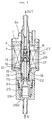
- Fig. 2 shows a prior art example of the electromagnetic pump for supplying fuel.
- a sleeve 4 is fitted on an end yoke 1 and an outer yoke 10.
- An inner yoke 6 is secured in position in the sleeve 4.
- a shock absorbing sheet 12 is applied to the lower end of the inner yoke 6.
- a plunger 18 is slidably fitted in the sleeve 4, such that it is biased downward by a compression coil spring 20 between a ring 19 and a lower flange and is held in forced contact with a packing 22.
- the compression coil spring 20 has a lower portion with a reduced diameter.
- the outer periphery of the sleeve 4 is sealed by an O-ring 15.
- An electromagnetic coil 13 is disposed in the outer yoke 10. A current flowing through the electromagnetic coil 13 generates a magnetic flux in an magnetic circuit, which is formed by the outer yoke 10, the end yoke 1, the inner yoke 6 and the plunger 18.
- a discharge valve sheet 28 is secured in position at the bottom of a central bore formed in the inner yoke 6.
- An intake valve 17 is biased by a compression coil spring 16 such that it enters a recess provided in the upper end surface of the plunger 18.
- a discharge valve 27 is slidably disposed in the center bore of the inner yoke 6, and is biased by a compression coil spring 7 to be in forced contact with the discharge valve sheet 28.
- the discharge valve 27 has a flow path groove formed in its outer periphery.
- a nipple 26 is fitted via a sealing O-ring 24 on a lower end portion of the outer yoke 10.
- the filter 25 is disposed and secured in a space defined by the outer yoke 10 and the nipple 26.
- the nipple 26 has a fuel suction port 26a.
- the inner yoke 6 has a fuel discharge port 6a.
- the negative pressure generated between the plunger 18 and the inner yoke 6 generates a gap between the intake valve 17 and the plunger 18, and liquid fuel flowing in through the fuel suction port 26a passes through the gap and fills the space, which is defined by the shock absorbing sheet 12, the plunger 18 and the top of the intake valve 17.
- the liquid fuel corresponding to the displacement volume of the plunger 18 is pumped out from the electromagnetic pump.
- the fuel discharge rate can be controlled according to the frequency of the current pulse output applied to the electromagnetic coil 13.
- This electromagnetic pump is an electromagnetic piston pump, in which a pressure piston is driven by a spring and an electromagnetic piston, which is driven by an electromagnetic coil energized by a current obtained by half-wave rectifying commercial power.
- a spring-biased electromagnetic movable piece is provided in the liquid passage.
- the liquid passage is normally held closed by the electromagnetic movable piece, and is opened when the half-wave rectified current is applied to the electromagnetic coil. Since this electromagnetic pump is of pressure control type, the discharge pressure is controlled to be constant by a pressure control mechanism provided on the discharge side of the pump.
- the pressure control mechanism controls a flow control valve with a diaphragm such that pressure in a constant pressure chamber is constant.
- the blow-by phenomenon occurs due to the opening of the intake valve caused by the inertia of fluid in a pulsating current generated by the pump action, that is, the flow of fluid in the discharging direction through the intake valve in a theoretically closed state. This phenomenon results in flow rate changes due to the suction side pressure variations or like cause, thus making it difficult to obtain accurate pump discharge rate control.
- the fluid passage is held closed by the electromagnetic movable piece when the electromagnetic coil is not energized, hence the electromagnetic or manual on-off valve as noted above is not necessary.
- the pump is the pressure control type electromagnetic pump as noted above, it has a problem that it is difficult to control the flow rate due to using an orifice or a relief valve.
- the present invention was made in view of the foregoing, and its object is to provide a metering type electromagnetic pump, which permits flow control to be done simply and does not require any electromagnetic or a manual on-off valve for closing the fluid passage.
- the metering type electromagnetic pump comprises a metering type electromagnetic solenoid, a plunger driven thereby, a check valve disposed downstream the plunger and driven by the electromagnetic solenoid, and a discharge valve provided in an inner yoke, the check-valve being opened and the plunger being in a discharge stroke state when a current pulse output is turned on to energize the electromagnetic solenoid.
- the discharge rate is controlled by the frequency of the current pulse output for energizing the electromagnetic solenoid.
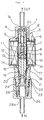
- Fig. 1 is a sectional view showing the embodiment of the metering type electromagnetic pump according to the invention.
- a sleeve 4 is fitted in an end yoke 1 and a nipple base 21.
- An inner yoke 6 is accommodated and secured in position in the sleeve 4.
- a shock absorbing sheet 12 is bonded to the lower end of the inner yoke 6.
- a plunger 18 is slidably accommodated in the sleeve 4.
- the plunger 18 is biased downward by a compression coil spring 20 provided between a ring 19 and a lower flange, and is held in forced contact with a packing 22 supported by a stopper 23.
- the compression coil spring 20 has a lower portion having a reduced diameter.
- the outer periphery of the sleeve 4 is sealed by O-rings 15 and 5.
- the outer yoke 10 accommodates an electromagnetic coil 13 disposed via spacer 14 in it. A current caused to pass through the electromagnetic coil 13 generates a flux in a magnetic circuit, which is formed by the outer yoke 10, the end yoke 1, a check valve 22, the inner yoke 6, the plunger 18 and the nipple base 21.
- the check valve 2 is slidably guided along the sleeve 4 and has a bore serving as a fluid passage, and its upper end has a projection 2a for closing a fuel discharge port 1a formed in the end yoke 1.
- the check valve 2 is normally closing the fuel discharge port 1a as sheet surface of the end yoke 1 is held in forced contact with the projection 2a by a compression coil spring 3.
- a discharge valve sheet 9 is secured in position at the bottom of a central bore formed in the inner yoke 6.
- the outer periphery of the inner yoke 76 is sealed by an O-ring 11.
- a suction valve 17 is energized by a compression coil spring 16 such as to enter a recess formed in the upper end surface of the plunger 18.
- a discharge valve 8 is slidably disposed in a central bore formed in the inner yoke 6, and is biased by a compression coil spring 7 to be in forced contact with a discharge valve sheet 9.
- the outer periphery of the discharge valve 8 has a groove forming a flow passage.
- a nipple 26 is fitted on a lower end portion of the nipple base 21 secured to the outer yoke 10.
- a filter 25 is secured in position between the nipple base 21 and the nipple 6.
- the nipple 26 has a fuel inlet port 26a.
- the check valve 2 is lowered againt the elastic force of the compression coil spring 7 by the suction force generated in the gap between the check valve 2 and the inner yoke 6, thus opening the fuel discharge port 1a to cause liquid fuel to be discharged through the hole in the check valve 2 and the the fuel outlet port 1a.
- a negative pressure generated between the plunger 18 and the inner yoke 6 generates a gap between the suction valve 17 and the plunger 18, and liquid fuel flowing from the fuel suction port 26a passes through the gap and fills the space defined by the shock absorbing sheet 12, the plunger 18 and the top of the suction valve 17.
- the check valve 2 When the electromagnetic coil 13 is de-energized, the check valve 2 is raised by the elastic force of the compression coil spring 3 and closes the fuel discharge port 1a. In the above way, since the fuel discharge port 1a is closed in the liquid fuel suction stroke, the blow-by phenomenon descried before in connection with the prior art can be suppressed. While both the check valve 2 and the discharge valve 8 are closed in the suction stroke, the dicharge valve 8 which has little mass is quickly brought into forced contact with the discharge valve sheet 9,and a negative pressure occures such that the suction valve 17 is opened, thus preventing reverse flow that may otherwise be cause in the suction stoke with the suction valve 17 in the closed state.
Landscapes
- Engineering & Computer Science (AREA)
- Mechanical Engineering (AREA)
- General Engineering & Computer Science (AREA)
- Physics & Mathematics (AREA)
- Fluid Mechanics (AREA)
- Chemical & Material Sciences (AREA)
- Combustion & Propulsion (AREA)
- Electromagnetic Pumps, Or The Like (AREA)
- Magnetically Actuated Valves (AREA)
Applications Claiming Priority (2)
| Application Number | Priority Date | Filing Date | Title |
|---|---|---|---|
| JP2281998 | 1998-01-20 | ||
| JP02281998A JP4203138B2 (ja) | 1998-01-20 | 1998-01-20 | 計量式電磁ポンプ |
Publications (2)
| Publication Number | Publication Date |
|---|---|
| EP0930434A2 true EP0930434A2 (fr) | 1999-07-21 |
| EP0930434A3 EP0930434A3 (fr) | 2000-05-24 |
Family
ID=12093307
Family Applications (1)
| Application Number | Title | Priority Date | Filing Date |
|---|---|---|---|
| EP99100306A Withdrawn EP0930434A3 (fr) | 1998-01-20 | 1999-01-11 | Pompe doseuse électromagnétique |
Country Status (3)
| Country | Link |
|---|---|
| EP (1) | EP0930434A3 (fr) |
| JP (1) | JP4203138B2 (fr) |
| KR (1) | KR19990067962A (fr) |
Cited By (5)
| Publication number | Priority date | Publication date | Assignee | Title |
|---|---|---|---|---|
| DE10103224C1 (de) * | 2001-01-25 | 2002-12-05 | Eberspaecher J Gmbh & Co | Dosierpumpanordnung und diese enthaltendes Dosierpumpsystem |
| FR2848263A1 (fr) * | 2002-12-06 | 2004-06-11 | Marwal Systems | Procede et dispositif perfectionnes de mesure de temperature , en vue d'un dosage de fluide liquide sur vehicule |
| FR2848264A1 (fr) * | 2002-12-06 | 2004-06-11 | Marwal Systems | Procede et dispositif perfectionnes de dosage de fluides liquides sur vehicule automobile |
| EP1398502A3 (fr) * | 2002-09-13 | 2006-11-15 | Mikuni Corporation | Pompe électromagnétique |
| DE10109948B4 (de) * | 2001-03-01 | 2008-02-21 | J. Eberspächer GmbH & Co. KG | Dosierpumpeinrichtung |
Families Citing this family (2)
| Publication number | Priority date | Publication date | Assignee | Title |
|---|---|---|---|---|
| US7174178B2 (en) * | 2001-07-19 | 2007-02-06 | Intel Corporation | Deriving a more accurate estimate from prediction data in closed loop transmit diversity modes |
| JP6003137B2 (ja) * | 2012-03-23 | 2016-10-05 | 株式会社不二越 | 電磁駆動ポンプ |
Citations (1)
| Publication number | Priority date | Publication date | Assignee | Title |
|---|---|---|---|---|
| JPS5238243A (en) | 1975-09-22 | 1977-03-24 | Toshiba Corp | Process for connecting power source for measurements of characteristic properties |
Family Cites Families (5)
| Publication number | Priority date | Publication date | Assignee | Title |
|---|---|---|---|---|
| US3874822A (en) * | 1973-10-31 | 1975-04-01 | Tadashi Nakamura | Electromagnetic plunger pump |
| JPS5724463A (en) * | 1980-07-16 | 1982-02-09 | Taisan Kogyo Kk | Automatic air extractor for electromagnetic plunger pump |
| US4504198A (en) * | 1980-09-08 | 1985-03-12 | Taisan Industrial Co., Ltd. | Electromagnetic pump |
| JPH0441260Y2 (fr) * | 1984-10-15 | 1992-09-28 | ||
| US4832583A (en) * | 1986-05-27 | 1989-05-23 | Facet Enterprises, Inc. | Low pressure metering fluid pump |
-
1998
- 1998-01-20 JP JP02281998A patent/JP4203138B2/ja not_active Expired - Fee Related
-
1999
- 1999-01-11 EP EP99100306A patent/EP0930434A3/fr not_active Withdrawn
- 1999-01-19 KR KR1019990001351A patent/KR19990067962A/ko not_active Withdrawn
Patent Citations (1)
| Publication number | Priority date | Publication date | Assignee | Title |
|---|---|---|---|---|
| JPS5238243A (en) | 1975-09-22 | 1977-03-24 | Toshiba Corp | Process for connecting power source for measurements of characteristic properties |
Cited By (6)
| Publication number | Priority date | Publication date | Assignee | Title |
|---|---|---|---|---|
| DE10103224C1 (de) * | 2001-01-25 | 2002-12-05 | Eberspaecher J Gmbh & Co | Dosierpumpanordnung und diese enthaltendes Dosierpumpsystem |
| DE10103224C5 (de) * | 2001-01-25 | 2006-01-26 | J. Eberspächer GmbH & Co. KG | Dosierpumpanordnung und diese enthaltendes Dosierpumpsystem |
| DE10109948B4 (de) * | 2001-03-01 | 2008-02-21 | J. Eberspächer GmbH & Co. KG | Dosierpumpeinrichtung |
| EP1398502A3 (fr) * | 2002-09-13 | 2006-11-15 | Mikuni Corporation | Pompe électromagnétique |
| FR2848263A1 (fr) * | 2002-12-06 | 2004-06-11 | Marwal Systems | Procede et dispositif perfectionnes de mesure de temperature , en vue d'un dosage de fluide liquide sur vehicule |
| FR2848264A1 (fr) * | 2002-12-06 | 2004-06-11 | Marwal Systems | Procede et dispositif perfectionnes de dosage de fluides liquides sur vehicule automobile |
Also Published As
| Publication number | Publication date |
|---|---|
| KR19990067962A (ko) | 1999-08-25 |
| EP0930434A3 (fr) | 2000-05-24 |
| JPH11210618A (ja) | 1999-08-03 |
| JP4203138B2 (ja) | 2008-12-24 |
Similar Documents
| Publication | Publication Date | Title |
|---|---|---|
| US4247077A (en) | Slow-opening valve operated by a solenoid pump | |
| US5118076A (en) | Control valve | |
| EP0328696B1 (fr) | Ensemble de clapet | |
| US6758657B1 (en) | Electromagnetically driven diaphragm pump | |
| US3302582A (en) | Electromagnetic pump | |
| JPS59194073A (ja) | 電磁式ユニツト型燃料噴射器 | |
| US4278406A (en) | Electromagnetic pump | |
| EP0930434A2 (fr) | Pompe doseuse électromagnétique | |
| US4352645A (en) | Solenoid pump adapted for noiseless operation | |
| US4749343A (en) | High pressure fluid pump | |
| JPH0140231B2 (fr) | ||
| JPH08177725A (ja) | プライミングピストン装置及び往復液体ポンプ | |
| US3874822A (en) | Electromagnetic plunger pump | |
| EP0411564A2 (fr) | Pompe à liquides | |
| US4413953A (en) | Two-stage hydraulic piston pump | |
| JP2002039057A (ja) | 電磁ポンプ | |
| US4725208A (en) | Positive shut off electromagnetic fluid pump | |
| KR0171555B1 (ko) | 전자 펌프 | |
| US4189285A (en) | Metering pump | |
| JP3759082B2 (ja) | 液体供給装置 | |
| JP2545894B2 (ja) | 流体制御用電磁弁 | |
| KR0171554B1 (ko) | 전자 펌프 | |
| KR940002071B1 (ko) | 압력상승시간 조정기구를 지닌 자동조정압력식 전자펌프 | |
| JPS6224153Y2 (fr) | ||
| JP3648708B2 (ja) | 電磁ポンプ |
Legal Events
| Date | Code | Title | Description |
|---|---|---|---|
| PUAI | Public reference made under article 153(3) epc to a published international application that has entered the european phase |
Free format text: ORIGINAL CODE: 0009012 |
|
| AK | Designated contracting states |
Kind code of ref document: A2 Designated state(s): AT BE CH CY DE DK ES FI FR GB GR IE IT LI LU MC NL PT SE |
|
| AX | Request for extension of the european patent |
Free format text: AL;LT;LV;MK;RO;SI |
|
| PUAL | Search report despatched |
Free format text: ORIGINAL CODE: 0009013 |
|
| AK | Designated contracting states |
Kind code of ref document: A3 Designated state(s): AT BE CH CY DE DK ES FI FR GB GR IE IT LI LU MC NL PT SE |
|
| AX | Request for extension of the european patent |
Free format text: AL;LT;LV;MK;RO;SI |
|
| STAA | Information on the status of an ep patent application or granted ep patent |
Free format text: STATUS: THE APPLICATION HAS BEEN WITHDRAWN |
|
| 18W | Application withdrawn |
Withdrawal date: 20000915 |