EP0930507A1 - Messanordnung für Wechselstrom oder Gleichstrom - Google Patents
Messanordnung für Wechselstrom oder Gleichstrom Download PDFInfo
- Publication number
- EP0930507A1 EP0930507A1 EP99400071A EP99400071A EP0930507A1 EP 0930507 A1 EP0930507 A1 EP 0930507A1 EP 99400071 A EP99400071 A EP 99400071A EP 99400071 A EP99400071 A EP 99400071A EP 0930507 A1 EP0930507 A1 EP 0930507A1
- Authority
- EP
- European Patent Office
- Prior art keywords
- field
- current
- magnetic
- sensor
- measurement
- Prior art date
- Legal status (The legal status is an assumption and is not a legal conclusion. Google has not performed a legal analysis and makes no representation as to the accuracy of the status listed.)
- Granted
Links
- 230000003071 parasitic effect Effects 0.000 claims abstract description 13
- 239000004020 conductor Substances 0.000 claims abstract description 6
- 238000005259 measurement Methods 0.000 claims description 28
- 238000004804 winding Methods 0.000 abstract description 2
- 230000000694 effects Effects 0.000 description 4
- 238000010586 diagram Methods 0.000 description 3
- 244000045947 parasite Species 0.000 description 2
- 238000010719 annulation reaction Methods 0.000 description 1
- 238000001514 detection method Methods 0.000 description 1
- 238000003780 insertion Methods 0.000 description 1
- 230000037431 insertion Effects 0.000 description 1
- 238000004519 manufacturing process Methods 0.000 description 1
- 230000035945 sensitivity Effects 0.000 description 1
Images

Classifications
-
- G—PHYSICS
- G01—MEASURING; TESTING
- G01R—MEASURING ELECTRIC VARIABLES; MEASURING MAGNETIC VARIABLES
- G01R15/00—Details of measuring arrangements of the types provided for in groups G01R17/00 - G01R29/00, G01R33/00 - G01R33/26 or G01R35/00
- G01R15/14—Adaptations providing voltage or current isolation, e.g. for high-voltage or high-current networks
- G01R15/20—Adaptations providing voltage or current isolation, e.g. for high-voltage or high-current networks using galvano-magnetic devices, e.g. Hall-effect devices, i.e. measuring a magnetic field via the interaction between a current and a magnetic field, e.g. magneto resistive or Hall effect devices
- G01R15/207—Constructional details independent of the type of device used
Definitions
- the invention relates to a current measurement arrangement. alternating or continuous, of the type comprising means generators of a magnetic field from the current to measure, a magnetic field sensor device generated and a measurement circuit which determines the value of said current.
- the object of the present invention is to provide a measurement arrangement which overcomes the disadvantages of the state of the art, which have just been stated.
- the arrangement according to the invention is characterized in that the means for reducing external influences include a sensor device the parasitic magnitude and a circuit for correcting external influences, suitable for applying a value correction to the aforementioned measurement circuit.
- the parasitic quantity sensor device comprises at minus a magnetic field sensor, placed at the near the magnetic field parasite.
- the correction circuit includes updating means the scale of the stray field value measured and application of the value in the inverted state at a point predetermined of the aforementioned measurement circuit.
- the correction sensor is arranged at the same angle vis-à-vis the stray field lines that the sensor measurement relative to the magnetic field lines at measure.
- the correction value is applied to a current amplifier mounted in the field cancellation coil circuit.
- the correction value is applied to the input of an operational amplifier mounted in the measuring circuit.
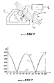
- the conductor in which the current to be measured has the reference number 1.
- the arrangement for measuring this current comprises a torus magnetic 2 which surrounds the conductor 1 and is provided an air gap 3 in which a sensor 4 of the magnetic field generated by the current to be measured, in the magnetic torus 2.
- the sensor 4 produces a signal electrical which is applied to an electronic circuit 6 intended to produce the representative measurement signal Vs of the current flowing in the conductor 1.
- the measurement arrangement is of the field cancellation type magnetic generated and has a coil 7 wound around the magnetic torus 2 and intended to produce the magnetic field inside the torus, which cancels the magnetic field produced by the current to be measured circulating in the conductor 1.
- the coil is connected to the circuit 6.
- the magnetic torus is exposed to a magnetic field parasitic exterior whose field lines are represented by broken lines 9. We see that the external field is deformed in the vicinity of the torus.
- a field sensor magnetic is placed in the stray field at vicinity of the sensitive area to this field.
- the sensor 10 is arranged so as to have the same angle to the field lines parasite 9 that the measurement sensor 4 relative to the magnetic field generated by the current to be measured.
- the sensor 10 is placed substantially perpendicular to the field lines 9.
- the sensor 10 is connected to an electronic circuit 12 of leveling of the signal produced so that it can be applied, in the form of a signal Vc correction to measurement circuit 6.
- FIG. 2 illustrates by three curves the effect of the correction device by showing the residual current measured in the presence of a uniform external parasitic field as a function of the angle between an ammeter clamp and the external field.
- Curve a indicates the current represented by the value Vs with correction and curve b this value without correction, curve c indicating the value of correction Vc.
- FIG. 3 shows in more detail the arrangement of the figure 1.
- the signal Vc after having been set at scale 12 is applied to the two inputs of a current amplifier 14 which is part of the circuit 6 of Figure 1.
- the arrangement of Figure 3 provides a potentiometer 15 for zero adjustment of one of the current amplifier inputs 14. The output of this is connected to the coil 7 and the measurement signal Vs is available as a voltage between the terminals of a adjustable resistance 16 mounted in series with the coil 7.
- References 17 and 18 indicate the power supplies in electrical energy respectively from the measure 4 and the stray field detection sensor 10.
- FIG. 4 illustrates the use of the invention in a current measurement arrangement by field measurement magnetic.
- the correction value Vc is applied to the two inputs of an amplifier operational 19 and the measurement signal Vs is produced in output of this amplifier.
- the value provided by the parasitic field sensor 10, after setting the scale, is added in opposition to a point of the circuit or measurement chain to minimize the influence of this field.
- the response from sensor 10, for circular rotation of the external field in the three axes x, y and z must match that of the measurement set within same conditions. For example, for a sensor of the type Hall we will obtain two lobes in 180 ° opposition. he the correction response should be in phase and of the same amplitude. The opposition of the two signals will cancel the disturbing effect of the external field.
Landscapes
- Physics & Mathematics (AREA)
- General Physics & Mathematics (AREA)
- Measuring Instrument Details And Bridges, And Automatic Balancing Devices (AREA)
- Measurement Of Current Or Voltage (AREA)
- Measuring Magnetic Variables (AREA)
Applications Claiming Priority (2)
| Application Number | Priority Date | Filing Date | Title |
|---|---|---|---|
| FR9800377 | 1998-01-15 | ||
| FR9800377A FR2773617B1 (fr) | 1998-01-15 | 1998-01-15 | Agencement de mesure de courant alternatif ou continu |
Publications (2)
| Publication Number | Publication Date |
|---|---|
| EP0930507A1 true EP0930507A1 (de) | 1999-07-21 |
| EP0930507B1 EP0930507B1 (de) | 2005-04-06 |
Family
ID=9521808
Family Applications (1)
| Application Number | Title | Priority Date | Filing Date |
|---|---|---|---|
| EP99400071A Expired - Lifetime EP0930507B1 (de) | 1998-01-15 | 1999-01-13 | Messanordnung für Wechselstrom oder Gleichstrom |
Country Status (5)
| Country | Link |
|---|---|
| US (1) | US6215296B1 (de) |
| EP (1) | EP0930507B1 (de) |
| DE (2) | DE930507T1 (de) |
| ES (1) | ES2146571T3 (de) |
| FR (1) | FR2773617B1 (de) |
Cited By (2)
| Publication number | Priority date | Publication date | Assignee | Title |
|---|---|---|---|---|
| EP1074848A1 (de) * | 1999-08-03 | 2001-02-07 | Eaton Corporation | Elektrischer Stromsensor |
| WO2015071102A1 (de) * | 2013-11-15 | 2015-05-21 | Epcos Ag | Vorrichtung, anordnung und verfahren zur messung einer stromstärke in einem stromdurchflossenen primärleiter |
Families Citing this family (12)
| Publication number | Priority date | Publication date | Assignee | Title |
|---|---|---|---|---|
| US7164263B2 (en) * | 2004-01-16 | 2007-01-16 | Fieldmetrics, Inc. | Current sensor |
| US7227441B2 (en) | 2005-02-04 | 2007-06-05 | Schweitzer Engineering Laboratories, Inc. | Precision Rogowski coil and method for manufacturing same |
| US7227442B2 (en) * | 2005-04-01 | 2007-06-05 | Schweitzer Engineering Laboratories, Inc. | Precision printed circuit board based rogowski coil and method for manufacturing same |
| US7545138B2 (en) | 2006-07-06 | 2009-06-09 | Schweitzer Engineering Laboratories, Inc. | Precision, temperature-compensated, shielded current measurement device |
| US8593133B2 (en) * | 2010-12-29 | 2013-11-26 | General Electric Company | Current measuring systems and methods of assembling the same |
| US8928337B2 (en) | 2012-01-27 | 2015-01-06 | Schweitzer Engineering Laboratories, Inc. | Device for measuring electrical current and method of manufacturing the same |
| US9535098B2 (en) * | 2013-09-02 | 2017-01-03 | Senis Ag | Current transducer for measuring an electrical current |
| US10228398B2 (en) * | 2015-04-02 | 2019-03-12 | Rosemount Aerospace Inc. | System and method for minimizing magnetic field effect on an isolated magnetometer |
| US10823764B2 (en) * | 2017-09-01 | 2020-11-03 | Te Connectivity Corporation | Hall effect current sensor |
| US11617269B2 (en) | 2021-07-20 | 2023-03-28 | Schweitzer Engineering Laboratories, Inc. | Current measuring device for an electric power protection system |
| CN113702683B (zh) * | 2021-08-03 | 2023-10-27 | 广西电网有限责任公司南宁供电局 | 电流测量装置、方法、计算机设备和存储介质 |
| US12601763B2 (en) | 2023-12-19 | 2026-04-14 | Schweitzer Engineering Laboratories, Inc. | Current sensor with adjacent conductor rejection |
Citations (1)
| Publication number | Priority date | Publication date | Assignee | Title |
|---|---|---|---|---|
| WO1990011529A1 (en) * | 1989-03-23 | 1990-10-04 | Abb Strömberg Kojeet Oy | Apparatus and method for measuring electric current in conditions of high interference |
Family Cites Families (3)
| Publication number | Priority date | Publication date | Assignee | Title |
|---|---|---|---|---|
| CH674088A5 (de) * | 1987-10-16 | 1990-04-30 | Lem Liaisons Electron Mec | |
| US5459395A (en) * | 1993-07-06 | 1995-10-17 | General Electric Company | Reduced flux current sensor |
| JP3007553B2 (ja) * | 1995-03-24 | 2000-02-07 | 日本レム株式会社 | 電流センサ |
-
1998
- 1998-01-15 FR FR9800377A patent/FR2773617B1/fr not_active Expired - Lifetime
-
1999
- 1999-01-13 ES ES99400071T patent/ES2146571T3/es not_active Expired - Lifetime
- 1999-01-13 DE DE0930507T patent/DE930507T1/de active Pending
- 1999-01-13 EP EP99400071A patent/EP0930507B1/de not_active Expired - Lifetime
- 1999-01-13 DE DE69924540T patent/DE69924540T2/de not_active Expired - Lifetime
- 1999-01-13 US US09/229,830 patent/US6215296B1/en not_active Expired - Lifetime
Patent Citations (1)
| Publication number | Priority date | Publication date | Assignee | Title |
|---|---|---|---|---|
| WO1990011529A1 (en) * | 1989-03-23 | 1990-10-04 | Abb Strömberg Kojeet Oy | Apparatus and method for measuring electric current in conditions of high interference |
Cited By (3)
| Publication number | Priority date | Publication date | Assignee | Title |
|---|---|---|---|---|
| EP1074848A1 (de) * | 1999-08-03 | 2001-02-07 | Eaton Corporation | Elektrischer Stromsensor |
| WO2015071102A1 (de) * | 2013-11-15 | 2015-05-21 | Epcos Ag | Vorrichtung, anordnung und verfahren zur messung einer stromstärke in einem stromdurchflossenen primärleiter |
| US10018656B2 (en) | 2013-11-15 | 2018-07-10 | Epcos Ag | Device, arrangement, and method for measuring a current intensity in a primary conductor through which current flows |
Also Published As
| Publication number | Publication date |
|---|---|
| DE69924540D1 (de) | 2005-05-12 |
| DE930507T1 (de) | 2000-08-31 |
| US6215296B1 (en) | 2001-04-10 |
| EP0930507B1 (de) | 2005-04-06 |
| ES2146571T3 (es) | 2005-12-01 |
| FR2773617A1 (fr) | 1999-07-16 |
| ES2146571T1 (es) | 2000-08-16 |
| FR2773617B1 (fr) | 2000-02-25 |
| DE69924540T2 (de) | 2006-02-23 |
Similar Documents
| Publication | Publication Date | Title |
|---|---|---|
| EP0930507B1 (de) | Messanordnung für Wechselstrom oder Gleichstrom | |
| EP1977258B1 (de) | Verfahren zur gleichstrommessung mit grosser messungsschwankung, elektronische anordnung mit einer solchen messvorrichtung und vorrichtung zur stromabschaltung mit einer solchen anordnung | |
| EP1856484B1 (de) | Induktive winkelmesseinrichtung | |
| EP0583993B1 (de) | Mess-/Anordnung und -verfahren ab Grundniveau für Hochspannungsluftleitungen | |
| FR2608283A1 (fr) | Dispositif capteur de courant electrique | |
| EP0492029A1 (de) | Induktiver Näherungssensor | |
| FR2827962A1 (fr) | Dispositif de mesure a effet hall de l'intensite d'un courant electrique | |
| FR2696007A1 (fr) | Dispositif pour la mesure d'ions dans un gaz. | |
| FR3111746A1 (fr) | Procédé de détection de courants de fuite ou de défaut dans une installation électrique à partir d’un appareil de protection assurant au moins une protection différentielle et un tel appareil convenant à la mise en œuvre dudit procédé | |
| CH625889A5 (de) | ||
| EP1084417B1 (de) | Elektrischer stromsensor mit hoher bandbreite | |
| EP0772855B1 (de) | Brandmelder mit korrektur von störparametern | |
| FR2594956A1 (fr) | Dispositif de mesure de la vitesse angulaire d'un corps en rotation | |
| EP0492394B1 (de) | Gerät zur zerstörungsfreien Untersuchung mit Wirbelströmen mit Umschaltung zur Flussaddition-Flusssubtraktion | |
| FR2609798A3 (fr) | Circuit en pont pour la detection de l'attitude d'un vehicule | |
| FR2510805A1 (fr) | Dispositif de compensation des champs magnetiques de corps mobiles | |
| CH424977A (fr) | Dispositif de mesure de l'impédance effective d'une partie de ligne électrique | |
| EP0783110B1 (de) | Stromfühler mit grossem Betriebsbereich | |
| EP2048510B1 (de) | Vorrichtung zum Testen der Funktionsfähigkeit eines Magnetfeldgenerators | |
| FR2752059A1 (fr) | Dispositif de mesure d'un courant circulant dans un conducteur | |
| EP4296694B1 (de) | Messzange für ac- und dc-leckströme | |
| FR2657957A1 (fr) | Dispositif de mesure du defilement d'une chaine. | |
| FR2687478A1 (fr) | Dispositif de mesure d'un gradient de champ magnetique dont les erreurs de sensibilite et de desalignement sont minimisees. | |
| FR3007845A1 (fr) | Capteur de detection d’un champ magnetique periodique emis par un codeur | |
| EP0517587A1 (de) | Einrichtung zum Messen der Winkellage einer Drosselklappe einer Brennkraftmaschine mit elektronischer Einspritzung |
Legal Events
| Date | Code | Title | Description |
|---|---|---|---|
| PUAI | Public reference made under article 153(3) epc to a published international application that has entered the european phase |
Free format text: ORIGINAL CODE: 0009012 |
|
| AK | Designated contracting states |
Kind code of ref document: A1 Designated state(s): DE ES GB IT |
|
| AX | Request for extension of the european patent |
Free format text: AL;LT;LV;MK;RO;SI |
|
| 17P | Request for examination filed |
Effective date: 19991015 |
|
| AKX | Designation fees paid |
Free format text: DE ES GB IT |
|
| GBC | Gb: translation of claims filed (gb section 78(7)/1977) | ||
| REG | Reference to a national code |
Ref country code: ES Ref legal event code: BA2A Ref document number: 2146571 Country of ref document: ES Kind code of ref document: T1 |
|
| DET | De: translation of patent claims | ||
| 17Q | First examination report despatched |
Effective date: 20020912 |
|
| GRAP | Despatch of communication of intention to grant a patent |
Free format text: ORIGINAL CODE: EPIDOSNIGR1 |
|
| GRAS | Grant fee paid |
Free format text: ORIGINAL CODE: EPIDOSNIGR3 |
|
| GRAA | (expected) grant |
Free format text: ORIGINAL CODE: 0009210 |
|
| AK | Designated contracting states |
Kind code of ref document: B1 Designated state(s): DE ES GB IT |
|
| REG | Reference to a national code |
Ref country code: GB Ref legal event code: FG4D Free format text: NOT ENGLISH |
|
| REF | Corresponds to: |
Ref document number: 69924540 Country of ref document: DE Date of ref document: 20050512 Kind code of ref document: P |
|
| GBT | Gb: translation of ep patent filed (gb section 77(6)(a)/1977) |
Effective date: 20050713 |
|
| REG | Reference to a national code |
Ref country code: ES Ref legal event code: FG2A Ref document number: 2146571 Country of ref document: ES Kind code of ref document: T3 |
|
| PLBE | No opposition filed within time limit |
Free format text: ORIGINAL CODE: 0009261 |
|
| STAA | Information on the status of an ep patent application or granted ep patent |
Free format text: STATUS: NO OPPOSITION FILED WITHIN TIME LIMIT |
|
| 26N | No opposition filed |
Effective date: 20060110 |
|
| PGFP | Annual fee paid to national office [announced via postgrant information from national office to epo] |
Ref country code: ES Payment date: 20180219 Year of fee payment: 20 Ref country code: GB Payment date: 20180130 Year of fee payment: 20 |
|
| PGFP | Annual fee paid to national office [announced via postgrant information from national office to epo] |
Ref country code: IT Payment date: 20180129 Year of fee payment: 20 |
|
| PGFP | Annual fee paid to national office [announced via postgrant information from national office to epo] |
Ref country code: DE Payment date: 20180329 Year of fee payment: 20 |
|
| REG | Reference to a national code |
Ref country code: DE Ref legal event code: R071 Ref document number: 69924540 Country of ref document: DE |
|
| REG | Reference to a national code |
Ref country code: GB Ref legal event code: PE20 Expiry date: 20190112 |
|
| PG25 | Lapsed in a contracting state [announced via postgrant information from national office to epo] |
Ref country code: GB Free format text: LAPSE BECAUSE OF EXPIRATION OF PROTECTION Effective date: 20190112 |
|
| REG | Reference to a national code |
Ref country code: ES Ref legal event code: FD2A Effective date: 20200902 |
|
| PG25 | Lapsed in a contracting state [announced via postgrant information from national office to epo] |
Ref country code: ES Free format text: LAPSE BECAUSE OF EXPIRATION OF PROTECTION Effective date: 20190114 |