EP0930510A2 - Bobine de détection pour appareil de diagnostic par résonance magnétique - Google Patents
Bobine de détection pour appareil de diagnostic par résonance magnétique Download PDFInfo
- Publication number
- EP0930510A2 EP0930510A2 EP98310383A EP98310383A EP0930510A2 EP 0930510 A2 EP0930510 A2 EP 0930510A2 EP 98310383 A EP98310383 A EP 98310383A EP 98310383 A EP98310383 A EP 98310383A EP 0930510 A2 EP0930510 A2 EP 0930510A2
- Authority
- EP
- European Patent Office
- Prior art keywords
- coil
- diagnostic apparatus
- detecting coil
- subject
- detecting
- Prior art date
- Legal status (The legal status is an assumption and is not a legal conclusion. Google has not performed a legal analysis and makes no representation as to the accuracy of the status listed.)
- Granted
Links
Images




Classifications
-
- G—PHYSICS
- G01—MEASURING; TESTING
- G01R—MEASURING ELECTRIC VARIABLES; MEASURING MAGNETIC VARIABLES
- G01R33/00—Arrangements or instruments for measuring magnetic variables
- G01R33/20—Arrangements or instruments for measuring magnetic variables involving magnetic resonance
- G01R33/28—Details of apparatus provided for in groups G01R33/44 - G01R33/64
- G01R33/32—Excitation or detection systems, e.g. using radio frequency signals
- G01R33/34—Constructional details, e.g. resonators, specially adapted to MR
- G01R33/341—Constructional details, e.g. resonators, specially adapted to MR comprising surface coils
-
- G—PHYSICS
- G01—MEASURING; TESTING
- G01R—MEASURING ELECTRIC VARIABLES; MEASURING MAGNETIC VARIABLES
- G01R33/00—Arrangements or instruments for measuring magnetic variables
- G01R33/20—Arrangements or instruments for measuring magnetic variables involving magnetic resonance
- G01R33/28—Details of apparatus provided for in groups G01R33/44 - G01R33/64
- G01R33/32—Excitation or detection systems, e.g. using radio frequency signals
- G01R33/34—Constructional details, e.g. resonators, specially adapted to MR
- G01R33/34046—Volume type coils, e.g. bird-cage coils; Quadrature bird-cage coils; Circularly polarised coils
-
- G—PHYSICS
- G01—MEASURING; TESTING
- G01R—MEASURING ELECTRIC VARIABLES; MEASURING MAGNETIC VARIABLES
- G01R33/00—Arrangements or instruments for measuring magnetic variables
- G01R33/20—Arrangements or instruments for measuring magnetic variables involving magnetic resonance
- G01R33/28—Details of apparatus provided for in groups G01R33/44 - G01R33/64
- G01R33/32—Excitation or detection systems, e.g. using radio frequency signals
- G01R33/34—Constructional details, e.g. resonators, specially adapted to MR
- G01R33/34084—Constructional details, e.g. resonators, specially adapted to MR implantable coils or coils being geometrically adaptable to the sample, e.g. flexible coils or coils comprising mutually movable parts
Definitions
- the present invention relates to a detecting coil for a magnetic resonance (MR) diagnostic apparatus, and more particularly, to such a coil which is improved so as not to nip the clothes or skin of a subject between the joining portions-of coil members when the coil is fitted around a region of the subject such as the leg or neck.
- MR magnetic resonance
- Japanese Patent Application Laid Open No's. 4-354934(1992) and 6-254068(1994) disclose an RF (radio frequency) coil for an MR imaging apparatus which can be separated into an upper structure and a lower structure and is cylindrically shaped when these structures are integrally joined.
- the split detecting coil as disclosed in the above applications is formed so that the coil is in close contact with the region of the subject to be examined such as the leg or neck, in order to efficiently receive an MR signal.
- the coil members are therefore liable to nip the clothes or skin of the subject between their joining portions when they are integrally joined around the region such as the leg or neck of the subject.
- the present invention provides a detecting coil for an MR diagnostic apparatus which consists of two or more coil members and has a cylindrical or annular shape when the coil members are integrally joined, wherein a part or the entirety of each joining portion of the two or more coil members is provided with an elastomeric guard portion.
- catching of the clothes and skin of a subject between the joining portions of the coil members is made unlikely by the cushioning effect of the guard portions.
- the clothes and skin of the subject are thus prevented from being nipped when the coil is fitted around the region such as the leg or neck of the subject.
- the present invention provides an additional advantage that the coil member is protected from damage when accidentally dropped or bumped against a table etc., because the shock is absorbed by the cushioning effect of the guard portion.
- Elastomer materials usable in the present invention include: silicone rubbers, nitrile rubbers, fluororubbers, chloroprene rubbers, polyurethane rubbers, butyl rubbers, Thiokol rubbers, polybutadiene rubbers and styrene-butadiene rubbers.
- the present invention provides the detecting coil for an MR diagnostic apparatus of the foregoing structure, wherein the hardness of the elastomer as determined by the JIS spring hardness test is Hs50 - Hs80.
- the inventors' studies show that when the hardness of the elastomer as determined by the JIS spring hardness test is less than Hs50, the guard portion is too soft and poor in durability, and when it is more than Hs80, the guard portion is too hard and is difficult to mold.
- a hardness in the range of from Hs50 to Hs80 inclusive provides moderate cushioning properties and is preferred.
- the likelihood of the clothes and skin of a subject being caught between the joining portions of the coil members is greatly reduced by the cushioning effect of the guard portions, thereby preventing the clothes and skin of the subject from being nipped between the joining portions of the coil members.
- the coil member is protected from damage when accidentally dropped or bumped, because the shock is absorbed by the cushioning effect of the guard portion.
- Figure 1 is an exploded perspective view of a detecting coil for an MR diagnostic apparatus in accordance with a first embodiment of the present invention.
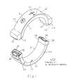
- Figure 2 is a perspective view of the detecting coil for an MR diagnostic apparatus in accordance with the first embodiment in the assembled state.
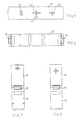
- Figure 3 is a front elevational view of the detecting coil for an MR diagnostic apparatus in accordance with the first embodiment.
- Figure 4 is a rear elevational view of the detecting coil for an MR diagnostic apparatus in accordance with the first embodiment.
- Figure 5 is a top plan view of the detecting coil for an MR diagnostic apparatus in accordance with the first embodiment.
- Figure 6 is a bottom plan view of the detecting coil for an MR diagnostic apparatus in accordance with the first embodiment.
- Figure 7 is a left side view of the detecting coil for an MR diagnostic apparatus in accordance with the first embodiment.
- Figure 8 is a right side view of the detecting coil for an MR diagnostic apparatus in accordance with the first embodiment.
- Figure 9 is a right side view of the detecting coil for an MR diagnostic apparatus in accordance with the first embodiment.
- Figure 10 is an exploded perspective view of a detecting coil for an MR diagnostic apparatus in accordance with a second embodiment of the present invention.
- Figure 11 is a perspective view of a detecting coil for an MR diagnostic apparatus in accordance with a third embodiment of the present invention.
- Figure 1 is an exploded perspective view of a detecting coil for an MR diagnostic apparatus in accordance with a first embodiment of the present invention.
- the detecting coil 100 for an MR diagnostic apparatus consists of a semi-annular upper coil member 10 and a semi-annular lower coil member 20.
- the upper coil member 10 is covered with covers 11, 12 of urethane resin, and has electrical connectors 13, 14 and locking levers 15, 16 at its joining portions.
- the lower coil member 20 is covered with covers 21, 22 of urethane resin, and has electrical connectors 23, 24 and locking concavities 25, 26 at its joining portions.
- guards 27, 28 of a silicone rubber having a hardness of Hs80.
- the guards 27, 28 protrude upwardly about 15 mm above the surfaces of the connectors 23, 24.
- the outer ends of the guards 27, 28 are cut obliquely.
- Reference symbol 'a' designates a hole for a signal cable
- 'b1' designates a registration mark to which an alignment laser beam is adjusted when the coil is used for a subject raised up (e.g., in imaging the neck region)
- 'b2' and 'b3' each designates a registration mark to which the alignment laser beam is adjusted when the coil is used rotated 45 degrees (e.g., in imaging the knee region)
- 'c1' and 'c2' each designates an alignment mark for orienting the upper coil member 10 and the lower coil member 20.
- Figure 2 is a perspective view showing the upper coil member 10 and the lower coil member 20 integrally joined to form the annular detecting coil 100 for an MR diagnostic apparatus.
- Figure 3 is a front elevational view
- Figure 4 is a rear elevational view
- Figure 5 is a top plan view
- Figure 6 is a bottom plan view
- Figure 7 is a left side view
- Figure 8 is a right side view, of the detecting coil 100 for an MR diagnostic apparatus.
- Figure 9 illustrates the detecting coil 100 of an MR diagnostic apparatus being fitted around the neck of a subject.
- the lower coil member 20 is disposed in a space between a bed B and the neck of the subject H lying thereon.
- the upper coil member 10 is then integrally joined with the lower coil member 20 so that it covers the neck of the subject H. This helps to prevent the clothes and skin of the subject H from resting on the joining portions of the lower coil member 20 because the guards 27, 28 protrude from the joining portions of the lower coil member 20. The clothes and skin of the subject H can be thus prevented from being nipped between the lower coil member 20 and the upper coil member 10.
- the guards 27, 28 serve also as guides for the joining.
- the lower coil member 20 is protected from damage to the connectors 23, 24 etc. when it is accidentally dropped or bumped against a table etc., because the shock is absorbed by the cushioning effect of the guards 27, 28.
- Figure 10 is an exploded perspective view of a detecting coil for an MR diagnostic apparatus in accordance with a second embodiment of the present invention.
- the detecting coil 100A for an MR diagnostic apparatus consists of a semi-annular upper coil member 10A and a pedestal-like lower coil member 20A, and is used for limb imaging.
- the lower coil member 20A is provided at its joining portions with a connector 23A etc., and guards 27A, 28A of a silicone rubber having a hardness of Hs80.
- Figure 11 is a perspective view of a detecting coil for an MR diagnostic apparatus in accordance with a third embodiment of the present invention.
- the detecting coil 100B for an MR diagnostic apparatus consists of a semi-annular upper coil member 10B and a pedestal-like lower coil member 20B, and is used for imaging the head region.
- the upper coil member 10B and the lower coil member 20B are pivotally attached to each other at their respective ends, and the other ends are configured to be opened and closed.
- a connector 23B etc. At the joining portions on the side of the open-and-close ends are provided a connector 23B etc., and guards 27B, 28B of a silicone rubber having a hardness of Hs80.
Landscapes
- Physics & Mathematics (AREA)
- Condensed Matter Physics & Semiconductors (AREA)
- General Physics & Mathematics (AREA)
- Magnetic Resonance Imaging Apparatus (AREA)
Applications Claiming Priority (2)
| Application Number | Priority Date | Filing Date | Title |
|---|---|---|---|
| JP09359390A JP3113852B2 (ja) | 1997-12-26 | 1997-12-26 | 磁気共鳴診断機用検出コイル |
| JP35939097 | 1997-12-26 |
Publications (3)
| Publication Number | Publication Date |
|---|---|
| EP0930510A2 true EP0930510A2 (fr) | 1999-07-21 |
| EP0930510A3 EP0930510A3 (fr) | 2001-04-11 |
| EP0930510B1 EP0930510B1 (fr) | 2004-09-29 |
Family
ID=18464267
Family Applications (1)
| Application Number | Title | Priority Date | Filing Date |
|---|---|---|---|
| EP98310383A Expired - Lifetime EP0930510B1 (fr) | 1997-12-26 | 1998-12-17 | Bobine de détection pour appareil de diagnostic par résonance magnétique |
Country Status (7)
| Country | Link |
|---|---|
| US (1) | US6141580A (fr) |
| EP (1) | EP0930510B1 (fr) |
| JP (1) | JP3113852B2 (fr) |
| KR (1) | KR100338454B1 (fr) |
| CN (1) | CN1109250C (fr) |
| DE (1) | DE69826625T2 (fr) |
| TW (1) | TW452488B (fr) |
Cited By (2)
| Publication number | Priority date | Publication date | Assignee | Title |
|---|---|---|---|---|
| EP1516582A3 (fr) * | 2003-09-09 | 2005-04-27 | Esaote S.p.A. | Dispositif pour le positionnement d'un membre pour un système d'imagerie par résonance magnétique |
| US7042219B2 (en) | 2004-08-12 | 2006-05-09 | Esaote S.P.A. | Method for determining the condition of an object by magnetic resonance imaging |
Families Citing this family (14)
| Publication number | Priority date | Publication date | Assignee | Title |
|---|---|---|---|---|
| US6684096B2 (en) * | 2000-12-15 | 2004-01-27 | Berndt P. Schmit | Restraining apparatus and method for use in imaging procedures |
| JP3619485B2 (ja) | 2001-10-24 | 2005-02-09 | ジーイー・メディカル・システムズ・グローバル・テクノロジー・カンパニー・エルエルシー | Rfコイルおよび磁気共鳴撮影装置 |
| CN100516922C (zh) | 2003-06-13 | 2009-07-22 | 皇家飞利浦电子股份有限公司 | 用于磁共振成像的顶部拼合射频线圈及磁共振成像设备 |
| US20060173390A1 (en) * | 2005-01-31 | 2006-08-03 | Robert Van Wyk | Immobilizing assembly and methods for use in diagnostic and therapeutic procedures |
| US20110257513A1 (en) * | 2008-11-24 | 2011-10-20 | Micromri, Inc. | Immobilization apparatus for medical imaging |
| USD692139S1 (en) * | 2012-12-05 | 2013-10-22 | Donald Charles | Articulated imaging device |
| USD685479S1 (en) | 2012-12-05 | 2013-07-02 | Donald Charles | Articulated MRI device |
| EP2992350A1 (fr) * | 2013-05-02 | 2016-03-09 | Koninklijke Philips N.V. | Connecteur amovible et logements de bobine rf divisibles |
| USD701961S1 (en) * | 2013-07-29 | 2014-04-01 | Donald Charles | Portable imaging device |
| US10969447B2 (en) * | 2017-11-22 | 2021-04-06 | General Electric Company | Flexible radio frequency coil array with detachable straps for MR imaging |
| EP3740127A4 (fr) * | 2018-01-18 | 2021-07-21 | New York University | Système et procédé de surveillance de la glycémie à l'aide de spectroscopie par résonance magnétique |
| CN110464461A (zh) * | 2019-08-29 | 2019-11-19 | 中国科学技术大学 | 一种基于mri引导的介入手术导航装置 |
| EP4037564A4 (fr) * | 2019-10-03 | 2023-05-24 | Victoria Link Limited | Support de tête gonflable |
| US11686794B2 (en) * | 2020-10-09 | 2023-06-27 | Shanghai United Imaging Healthcare Co., Ltd. | Coil assembly and control method thereof |
Citations (2)
| Publication number | Priority date | Publication date | Assignee | Title |
|---|---|---|---|---|
| JPH04354934A (ja) | 1991-06-03 | 1992-12-09 | Toshiba Corp | 磁気共鳴イメージング装置用rfコイル |
| JPH06254068A (ja) | 1993-03-03 | 1994-09-13 | Toshiba Corp | 磁気共鳴イメージング装置 |
Family Cites Families (9)
| Publication number | Priority date | Publication date | Assignee | Title |
|---|---|---|---|---|
| DE3347597A1 (de) * | 1983-12-30 | 1985-07-18 | Philips Patentverwaltung Gmbh, 2000 Hamburg | Hochfrequenz-spulenanordnung zum erzeugen und/oder empfangen von wechselmagnetfeldern |
| JPH0616760B2 (ja) * | 1988-09-09 | 1994-03-09 | ザ・トラステイズ・オブ・ザ・ユーニバァスィティ・オブ・ペンシルバニア | 核磁気共鳴映像法で使用するためのコイル組立体 |
| US4897604A (en) * | 1989-02-21 | 1990-01-30 | The Regents Of The University Of California | Method and apparatus for selective adjustment of RF coil size for magnetic resonance imaging |
| EP0471509A3 (en) * | 1990-08-17 | 1992-09-09 | General Electric Company | Split nmr coil with improved connector |
| JPH0690923A (ja) * | 1992-09-17 | 1994-04-05 | Hitachi Ltd | 核磁気共鳴を用いた検出器 |
| DE4318134C2 (de) * | 1993-06-01 | 1999-02-11 | Siemens Ag | Zirkular polarisierende Lokalantenne |
| US5477146A (en) * | 1994-02-22 | 1995-12-19 | Board Of Regents - Univ Of Ne | NMR adjustable volume array |
| US5543710A (en) * | 1994-02-22 | 1996-08-06 | Board Of Regents Of Univ. Of Ne | NMR conformal solenoidal coil |
| US6023166A (en) * | 1997-11-19 | 2000-02-08 | Fonar Corporation | MRI antenna |
-
1997
- 1997-12-26 JP JP09359390A patent/JP3113852B2/ja not_active Expired - Fee Related
-
1998
- 1998-12-11 US US09/209,604 patent/US6141580A/en not_active Expired - Lifetime
- 1998-12-15 TW TW087120825A patent/TW452488B/zh not_active IP Right Cessation
- 1998-12-17 DE DE69826625T patent/DE69826625T2/de not_active Expired - Lifetime
- 1998-12-17 EP EP98310383A patent/EP0930510B1/fr not_active Expired - Lifetime
- 1998-12-22 KR KR1019980057007A patent/KR100338454B1/ko not_active Expired - Fee Related
- 1998-12-28 CN CN98126346A patent/CN1109250C/zh not_active Expired - Fee Related
Patent Citations (2)
| Publication number | Priority date | Publication date | Assignee | Title |
|---|---|---|---|---|
| JPH04354934A (ja) | 1991-06-03 | 1992-12-09 | Toshiba Corp | 磁気共鳴イメージング装置用rfコイル |
| JPH06254068A (ja) | 1993-03-03 | 1994-09-13 | Toshiba Corp | 磁気共鳴イメージング装置 |
Cited By (4)
| Publication number | Priority date | Publication date | Assignee | Title |
|---|---|---|---|---|
| EP1516582A3 (fr) * | 2003-09-09 | 2005-04-27 | Esaote S.p.A. | Dispositif pour le positionnement d'un membre pour un système d'imagerie par résonance magnétique |
| US7098660B2 (en) | 2003-09-09 | 2006-08-29 | Esaote S.P.A. | Diagnostic imaging apparatus and method for limbs, particularly the hand by means of nuclear magnetic resonance |
| US7042219B2 (en) | 2004-08-12 | 2006-05-09 | Esaote S.P.A. | Method for determining the condition of an object by magnetic resonance imaging |
| US7660619B2 (en) | 2004-08-12 | 2010-02-09 | Esaote S.P.A. | Method for determining the condition of an object by magnetic resonance imaging |
Also Published As
| Publication number | Publication date |
|---|---|
| JPH11188017A (ja) | 1999-07-13 |
| KR100338454B1 (ko) | 2002-09-17 |
| CN1109250C (zh) | 2003-05-21 |
| CN1226002A (zh) | 1999-08-18 |
| KR19990063294A (ko) | 1999-07-26 |
| TW452488B (en) | 2001-09-01 |
| DE69826625D1 (de) | 2004-11-04 |
| EP0930510B1 (fr) | 2004-09-29 |
| EP0930510A3 (fr) | 2001-04-11 |
| DE69826625T2 (de) | 2005-10-06 |
| JP3113852B2 (ja) | 2000-12-04 |
| US6141580A (en) | 2000-10-31 |
Similar Documents
| Publication | Publication Date | Title |
|---|---|---|
| EP0930510B1 (fr) | Bobine de détection pour appareil de diagnostic par résonance magnétique | |
| US6550913B2 (en) | Auxiliary eyewear attachment methods and apparatus | |
| US20070256946A1 (en) | Carrying case for headphones | |
| US7394256B2 (en) | Wrist coil for magnetic resonance imaging | |
| JPH0571804B2 (fr) | ||
| US20230007377A1 (en) | Personal acoustic systems and flexible earpiece mounts for the same | |
| USRE37545E1 (en) | Auxiliary lenses for eyeglasses | |
| US20020020005A1 (en) | Goggles | |
| US10566728B1 (en) | Electrical connector with high vibration resistant locks | |
| US20180363339A9 (en) | Vehicle liftgate striker and latch construction | |
| US20100156420A1 (en) | Local coil arrangement for magnetic resonance applications and patient bed for a magnetic resonance system, with integrated electrical interfaces | |
| JP2000279392A (ja) | Mri用ボディープローブ及びmri装置 | |
| JP2023548195A (ja) | 固定装置、当該固定装置を有する頭部保護具 | |
| US20040239505A1 (en) | Release techniques for a security tag | |
| US5483157A (en) | Rotary sensor having a stay and molded body | |
| KR102433444B1 (ko) | 전주탈부착형 가공배전선 지지기구 | |
| US12100911B2 (en) | Vibration resistant connector cap | |
| US20060166542A1 (en) | IC socket | |
| US20230393343A1 (en) | Locking ring for a cable closure | |
| US7377136B1 (en) | Computer security hook system with corresponding pegs, holes and rings | |
| KR100760848B1 (ko) | 다이어리 조립구조 | |
| KR101204473B1 (ko) | 차량용 볼조인트의 밀폐구조 | |
| KR200398495Y1 (ko) | 다이어리 조립구조 | |
| KR102898050B1 (ko) | 링형 플러그가 적용된 볼 조인트 | |
| KR100213358B1 (ko) | 진공청소기의 브러쉬 네크 고정구조 |
Legal Events
| Date | Code | Title | Description |
|---|---|---|---|
| PUAI | Public reference made under article 153(3) epc to a published international application that has entered the european phase |
Free format text: ORIGINAL CODE: 0009012 |
|
| AK | Designated contracting states |
Kind code of ref document: A2 Designated state(s): DE FR GB |
|
| AX | Request for extension of the european patent |
Free format text: AL;LT;LV;MK;RO;SI |
|
| PUAL | Search report despatched |
Free format text: ORIGINAL CODE: 0009013 |
|
| AK | Designated contracting states |
Kind code of ref document: A3 Designated state(s): AT BE CH CY DE DK ES FI FR GB GR IE IT LI LU MC NL PT SE |
|
| AX | Request for extension of the european patent |
Free format text: AL;LT;LV;MK;RO;SI |
|
| 17P | Request for examination filed |
Effective date: 20011011 |
|
| AKX | Designation fees paid |
Free format text: DE FR GB |
|
| 17Q | First examination report despatched |
Effective date: 20030603 |
|
| GRAP | Despatch of communication of intention to grant a patent |
Free format text: ORIGINAL CODE: EPIDOSNIGR1 |
|
| GRAS | Grant fee paid |
Free format text: ORIGINAL CODE: EPIDOSNIGR3 |
|
| GRAA | (expected) grant |
Free format text: ORIGINAL CODE: 0009210 |
|
| AK | Designated contracting states |
Kind code of ref document: B1 Designated state(s): DE FR GB |
|
| REG | Reference to a national code |
Ref country code: GB Ref legal event code: FG4D |
|
| REF | Corresponds to: |
Ref document number: 69826625 Country of ref document: DE Date of ref document: 20041104 Kind code of ref document: P |
|
| ET | Fr: translation filed | ||
| PLBE | No opposition filed within time limit |
Free format text: ORIGINAL CODE: 0009261 |
|
| STAA | Information on the status of an ep patent application or granted ep patent |
Free format text: STATUS: NO OPPOSITION FILED WITHIN TIME LIMIT |
|
| 26N | No opposition filed |
Effective date: 20050630 |
|
| PGFP | Annual fee paid to national office [announced via postgrant information from national office to epo] |
Ref country code: GB Payment date: 20071227 Year of fee payment: 10 |
|
| PGFP | Annual fee paid to national office [announced via postgrant information from national office to epo] |
Ref country code: FR Payment date: 20071217 Year of fee payment: 10 |
|
| GBPC | Gb: european patent ceased through non-payment of renewal fee |
Effective date: 20081217 |
|
| REG | Reference to a national code |
Ref country code: FR Ref legal event code: ST Effective date: 20090831 |
|
| PG25 | Lapsed in a contracting state [announced via postgrant information from national office to epo] |
Ref country code: GB Free format text: LAPSE BECAUSE OF NON-PAYMENT OF DUE FEES Effective date: 20081217 |
|
| PG25 | Lapsed in a contracting state [announced via postgrant information from national office to epo] |
Ref country code: FR Free format text: LAPSE BECAUSE OF NON-PAYMENT OF DUE FEES Effective date: 20081231 |
|
| PGFP | Annual fee paid to national office [announced via postgrant information from national office to epo] |
Ref country code: DE Payment date: 20131230 Year of fee payment: 16 |
|
| REG | Reference to a national code |
Ref country code: DE Ref legal event code: R119 Ref document number: 69826625 Country of ref document: DE |
|
| PG25 | Lapsed in a contracting state [announced via postgrant information from national office to epo] |
Ref country code: DE Free format text: LAPSE BECAUSE OF NON-PAYMENT OF DUE FEES Effective date: 20150701 |