EP0930698B1 - Procédé et système de pilotage de la vitesse de rotation d'un moteur DC à commutation électronique - Google Patents
Procédé et système de pilotage de la vitesse de rotation d'un moteur DC à commutation électronique Download PDFInfo
- Publication number
- EP0930698B1 EP0930698B1 EP98121751A EP98121751A EP0930698B1 EP 0930698 B1 EP0930698 B1 EP 0930698B1 EP 98121751 A EP98121751 A EP 98121751A EP 98121751 A EP98121751 A EP 98121751A EP 0930698 B1 EP0930698 B1 EP 0930698B1
- Authority
- EP
- European Patent Office
- Prior art keywords
- speed
- current
- transition
- control
- motor
- Prior art date
- Legal status (The legal status is an assumption and is not a legal conclusion. Google has not performed a legal analysis and makes no representation as to the accuracy of the status listed.)
- Expired - Lifetime
Links
- 238000000034 method Methods 0.000 title claims description 49
- 230000007704 transition Effects 0.000 claims description 31
- 230000001629 suppression Effects 0.000 claims description 9
- 230000008859 change Effects 0.000 claims description 7
- 238000011144 upstream manufacturing Methods 0.000 claims description 2
- 230000001276 controlling effect Effects 0.000 claims 2
- 230000001105 regulatory effect Effects 0.000 claims 1
- 238000010586 diagram Methods 0.000 description 8
- 230000008901 benefit Effects 0.000 description 6
- 230000004913 activation Effects 0.000 description 3
- 230000001419 dependent effect Effects 0.000 description 3
- 230000008569 process Effects 0.000 description 3
- 230000003111 delayed effect Effects 0.000 description 2
- 230000000694 effects Effects 0.000 description 2
- 230000009467 reduction Effects 0.000 description 2
- 239000004065 semiconductor Substances 0.000 description 2
- 230000003247 decreasing effect Effects 0.000 description 1
- 230000008030 elimination Effects 0.000 description 1
- 238000003379 elimination reaction Methods 0.000 description 1
- 230000006870 function Effects 0.000 description 1
- 238000004804 winding Methods 0.000 description 1
Images


Classifications
-
- H—ELECTRICITY
- H02—GENERATION; CONVERSION OR DISTRIBUTION OF ELECTRIC POWER
- H02P—CONTROL OR REGULATION OF ELECTRIC MOTORS, ELECTRIC GENERATORS OR DYNAMO-ELECTRIC CONVERTERS; CONTROLLING TRANSFORMERS, REACTORS OR CHOKE COILS
- H02P6/00—Arrangements for controlling synchronous motors or other dynamo-electric motors using electronic commutation dependent on the rotor position; Electronic commutators therefor
- H02P6/08—Arrangements for controlling the speed or torque of a single motor
- H02P6/085—Arrangements for controlling the speed or torque of a single motor in a bridge configuration
Definitions
- the present invention relates to a method and a system for speed control from - in particular collectorless and by means of Rotary position sensors controlled - DC motors, the motor current depending on the speed change is manipulated by a control signal.
- a brushless DC motor to control a semiconductor bridge circuit, wherein the motor in the bridge branch made of electronic switching elements (usually transistors) formed bridge circuit is arranged.
- the switching elements are from a driver stage, depending on sensor signals from at least one non-contact rotor rotational position sensor, usually a Hall element (Hall IC).
- the motor current pulses generated by the electronic commutation are shortened in time at the beginning of each commutation interval, that is, starting from the respective signal change of the rotary position sensor, by delayed switching on of at least one of the switching elements located in the respective current path.
- This method is generally known as current section pause control.
- the main disadvantage is that a disturbing commutation noise is noticeable at low motor speeds, especially since other running noises of the motor become weaker in the lower speed range, so that they take a back seat to the commutation noise.
- relatively high current peaks occur because the motor current switched on very late in the commutation interval rises very steeply and then drops steeply again (compare the current i ' 3 in the attached FIG. 9 d).
- PWM control Pulse width modulation
- the commutation-dependent Current pulses each with a constant clock frequency in Clock pulses are chopped.
- the clock pulses variable with regard to their pulse width or pulse width.
- Advantages of PWM control are in a stepless speed control and in one to see low-noise, almost noise-free mode of operation, the latter in any case if a clock frequency is above of 16 kHz and therefore outside the human hearing range is chosen.
- Claim 1 was in its preamble delimited from document US-A-5 457 374.
- This Document discloses a method for speed control of - in particular brushless and by means of rotor position sensors controlled - DC motors, the motor current in Dependence on a control signal is manipulated. In doing so, Manipulation of the motor current over the speed setting range (low motor speeds, high motor speeds) at least two different control methods applied, also automatically at a certain transition speed from one tax procedure to another tax procedure. As Control methods are, however, only a current control mode (current-controlled mode) and a voltage control mode (full-day controlled mode).
- Document US-A-5 225 759 describes another control method for a brushless DC motor. Basically, there are also two different tax procedures applied, namely Start a control independent of the rotor position, and from one The specified speed is controlled by evaluating the in the Stator windings induced back EMF and thus in dependence on the Rotor position.
- the document DE 43 10 260 C1 describes an electronic one Control device for an electronically commutated direct current motor (EC motor).
- EC motor electronically commutated direct current motor
- a linear control is provided for the speed range. This means that with one Current flow angle of 100% of the commutation angle the amplitude of the Control signal is increased with increasing speed up to a first speed. From this first speed, increasing in a medium speed range Speed up to a second speed the amplitude of the control signals up to a Maximum amplitude further increased, and at the same time the degree of activation of the Current flow angle reduced from 100% to a smaller value. From the second Speed, i.e.
- block control denotes what basically means that variable power breaks and correspondingly variable current blocks are generated. So dominates, in the upper Speed range block congestion, and dominates in the lower speed range Linear control, while practically both in a medium speed range Tax types are combined.
- the present invention is based on the object To create tax system of the type mentioned with which is a brushless, electronically commutated DC motor across the entire speed setting range with an optimal energy balance and particularly low noise can be controlled.
- an additional current tail suppression is provided, the motor current - in a manner known per se - in each case switched off before the end of each commutation interval is so that between each current pulse and the End of the associated commutation interval arise. It shows these current gaps each a constant, but adjustable if necessary Duration or angular extension of in particular about 15% of the respective commutation interval. This will on the one hand, safe suppression of the disadvantageous negative current tail, which on the other hand too leads to an additional gain in efficiency.
- the preferably additionally over the entire speed range constant current tail suppression provided also contributes to a good energy balance Elimination of harmful negative current tail areas at, and the earlier power cut leads to a power free Switch on the switching elements in each subsequent commutation interval, which is natural very positive on the lifespan of the electronic switching elements effect.
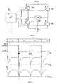
- FIG. 1 is a schematic diagram of a conventional circuit exemplary for a single-strand, electronically commutated DC motor M shown.
- the engine M is with a reluctance auxiliary torque for specifying a starting position equipped and lies within one of four electronic switching elements 2, 4, 6, 8 formed Bridge circuit in the bridge diagonal.
- the motor M is with a rotor rotation position sensor 10, in particular with a Hall sensor or Hall IC, the current Rotary position of the rotor determined.
- the output signals of the Sensors 10 are fed to a driver stage 12, which in is usually formed by a microcontroller ⁇ C.
- the switching elements 2 to 8 are controlled in a suitable manner by the driver stage 12, the transistors TDA and BDB and then the transistors TDB and BDA being controlled alternately in pairs. This results in changing current flow directions on the one hand from + U b , TDA, Motor M, BDB to the negative pole and on the other hand from + U b , TDB, M, BDA to negative.
- the sensor 10 When the motor M or its rotor rotates, the sensor 10 generates a signal which is dependent on the rotor position and which alternately assumes the values logically “low” (L) or logically “high” (H) and changes this value accordingly each time the polarity of the rotor magnet changes, as shown in Figure 2a. This results in typical motor currents i according to FIG. 2 b and torque curves according to FIG. 2 c. These variables are illustrated across the electrical rotor rotation angle ⁇ . Instead, the time axis t could in principle also be provided here.
- FIG. 3 shows the basic circuit diagram of a Execution.
- the driver stage 12 (see FIG. 1) was through an additional, upstream input interface 14 added.
- the task and mode of operation of this input interface 14 as well as the design or Programming the microcontroller Driver stage 12 will now be explained in more detail.
- a control signal U s is supplied to the input interface 14, which advantageously can be either an analog voltage or a frequency-constant signal in the form of a PWM signal.
- the input interface 14 is designed such that this control signal U s - regardless of its analog or pulse-width modulated type - is in any case converted into an analog control signal U x .
- the level can also be reduced in order to reduce the control signal U s to the voltage level of the driver stage 12.
- the control signal U x is an analog input control voltage that can be set from 0V to U xmax .
- the maximum input control voltage U xmax can be 5V, for example.
- a lower speed range - preferably with a control signal between 0V and about 0.5U xmax - and an upper speed range - preferably with an associated control signal between 0.5U xmax and U xmax - are now defined to differentiate between different operating states or different control methods .
- a control signal U x of U xmax is present at the control input of driver stage 12.
- the speed can now be reduced accordingly by reducing the control signal U x , for which purpose a first control method is first used.
- a certain transition speed of, in particular, approximately half the maximum speed, or with a corresponding transition value of the control signal U x of, in particular, approximately 0.5U xmax the system then automatically switches from one control method to another control method.
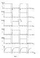
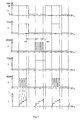
- FIG. 4 shows diagrams for the maximum speed.
- the motor current is commutated i each at the natural commutation time, d. H.
- the sensor signal With the respective change of the sensor signal begins the increase in motor current i.
- 4 a shows the sensor signal of the rotary position sensor, which each have a Outputs angle of rotation ⁇ of 180 ° electrically logically H or L.
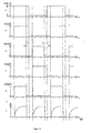
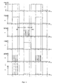
- the motor current i can now be changed in the upper speed range between the maximum speed and a transition speed by means of a current section pause control which is known per se. This is illustrated in FIGS. 5 and 6. If the control signal U x is reduced compared to the maximum value U xmax , the start of the activation times of all bridge switching elements 2 to 8 is shifted by a certain angle, as is shown in FIGS. 5 b to 5 e. This delayed switch-on leads to a current profile according to FIG. 5 f and thus to a corresponding speed reduction of the motor. If the control signal U x is reduced even further, the switch-on times of all switching elements are correspondingly shifted further and thus further away from the natural commutation time.
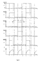
- This current segment pause control is only used until maximum current segment pauses SAP with a certain width of preferably about 40% of the total commutation interval are reached. This corresponds to a transition speed of approximately half the maximum speed. For a further reduction in the speed, the control signal U x is reduced below the transition value of 0.5U xmax , which means that a different control process is carried out independently. The previously reached value of approx. 40% of the current section breaks is kept constant.
- the two lower-level switching elements BDA and BDB are clocked with a high-frequency PWM signal during the switching phase of the corresponding upper-level switching elements TDB and TDA.
- a PWM clocking known per se is thus used in the lower speed range.
- the PWM frequency is preferably around 20 kHz, in any case outside the human hearing range.
- this measure is preferred constant over the entire speed range of the Engine applied.
- the motor current i before the end of each commutation interval turned off so that between each current pulse and the end of the associated commutation interval current gaps SSU emerge.
- These current gaps SSU each have a constant period of time or a constant angle of rotation of in particular about 15% of the respective commutation interval on. This ensures that the in Fig. 2 b recognizable negative current tails reliably be eliminated.
- the benefits of this measure have been above already explained.
- the current tail suppression takes place in that the Switching on the switching elements BDA and BDB before End of natural commutation time 180 ° or Ends 360 °. This causes the corresponding earlier shutdown of the motor current, as shown in Fig. 4 f is. Because this current tail suppression with in particular about 15% of the commutation interval remains constant, there is a maximum current flow duration for the maximum speed of 85%, which in turn is in 40% SAP control and split 45% PWM control.
- the invention leads to a significantly improved energy balance over the speed range away as well as for the power-free activation of the next switching elements after commutation.
- very low noise level as special even at low speeds Highlight advantage.
- FIG. 9 a shows the situation when the speed n1 corresponds approximately to half the maximum speed n max .
- FIG. 9 c a sawtooth-like current pulse i 2 is generated by the PWM timing at a speed n2 ⁇ n1, which extends over the entire area of 45% in particular between SAP and SSU, but is relatively flat.
- a current pulse i ' 2 is additionally drawn in in FIG. 9 c, which would arise if the SAP control were used beyond the transition value.
- This current pulse i ' 2 would be significantly shorter, but steeper, which becomes even clearer at a speed n3 ⁇ n2 according to FIG. 9d (cf. currents i 3 and i' 3 ). These very disadvantageous current peaks are avoided.
Landscapes
- Engineering & Computer Science (AREA)
- Power Engineering (AREA)
- Control Of Motors That Do Not Use Commutators (AREA)
Claims (14)
- Procédé de commande de la vitesse de rotation de moteurs à courant continu (M) sans collecteur et commandés au moyen de capteurs (10) de position de rotation du rotor, dans lequel, pour la modification de la vitesse de rotation, le courant (i) du moteur est manipulé en fonction d'un signal de commande (Ux) c'est pour cela, au moins deux procédés de commande différents sont utilisés sur la plage de réglage de la vitesse de rotation (n = n0 à nmax) du moteur (M), et, à une certaine vitesse de rotation de transition (nx) ou à une valeur de transition du signal de commande (Ux) qui y correspond, il se produit automatiquement un passage d'un procédé de commande à l'autre procédé de commande,
caractérisé en ce que, dans une plage supérieure de vitesses de rotation (n = nx à nmax), entre une vitesse de rotation maximale (nmax) et la vitesse de rotation de transition (nx), le courant du moteur (i) est modifié au moyen d'une commande des pauses de coupure de courant ( SAP) et en ce que, dans une plage inférieure de vitesses de rotation (n = n0 à nx), entre la vitesse de rotation de transition (nx) et la vitesse de rotation zéro (n0), le courant du moteur (i) est modifié par un cadençage variable d'impulsions de courant distinctes qui est modulée en largeur des impulsions (PWM). - Procédé selon la revendication 1,
caractérisé en ce que le niveau de la vitesse de rotation considérée (nx) ou de la valeur de transition du signal de commande (Ux) peut être modifiée par l'intermédiaire de moyens de réglage. - Procédé selon la revendication 1 ou 2,
caractérisé en ce que, à chaque fois en partant de points de commutation déterminés comme inversions de signal de capteur (H-L/L-H) au moyen d'un capteur de position de rotation (10), des pauses de coupure de courant (SAP) de durée variable sont produites par un établissement retardé de façon variable du courant (i) du moteur, de sorte que le courant (i) du moteur est composé d'impulsions de courant individuelles restantes, qui possèdent une durée variable ou une plage angulaire de rotation variable. - Procédé selon une des revendications 1 à 3,
caractérisé en ce que - rapporté à la durée, comptée dans le temps ou en angle de rotation, d'un intervalle de commutation limitée par deux inversions du signal de capteur - les pauses de coupure de courant (SAP) peuvent être modifiées dans un intervalle partiel entre zéro et au maximum d'environ 40% de l'intervalle de commutation. - Procédé selon une des revendications 1 à 4,
caractérisé en ce que les impulsions de courant cadencées en PWM présentent chacune une durée constante, comptée dans le temps ou en angle de rotation, qui est de préférence d'environ 45 % de l'intervalle de commutation concerné. - Procédé selon une des revendications 1 à 5,
caractérisé en ce que le cadençage PWM s'effectue avec une fréquence de cycle constante, qui est de préférence supérieure à une limite audible d'environ 16 kHz, en particulier égale à environ 20 kHz. - Procédé selon une des revendications 1 à 6,
caractérisé par une suppression additionnelle des queues de courant (SSU), dans laquelle le courant de moteur (i) est déjà coupé à chaque fois avant la fin de chaque intervalle de commutation, de sorte qu' il se forme des lacunes de courant (SSU) entre chaque impulsion de courant et la fin de l'intervalle de commutation correspondant. - Procédé selon la revendication 7,
caractérisé en ce que les lacunes de courant (SSU) présentent une durée constante, comptée dans le temps ou en angle de rotation - éventuellement réglable- qui est en particulier d'environ 15 % de l'intervalle de commutation correspondant. - Procédé selon une des revendications 1 à 8,
caractérisé en ce que la vitesse de rotation de transition (nx) correspond à peu près à la moitié de la vitesse de rotation maximale (nmax/2). - Procédé selon une des revendications 1 à 9,
caractérisé en ce que la valeur de transition du signal de commande (Ux) correspond à peu près à la moitié de la valeur maximale (Umax/2). - Procédé selon une des revendications 1 à 10,
caractérisé en ce que le moteur (M) est piloté au moyen d'un circuit en pont - composé d'éléments de circuit en pont (2, 4, 6, 8), les éléments de circuit (2-8) étant commandés par un étage d'attaque (12) - formé en particulier d'un microcontrôleur (µC) et présentant une entrée de commande pour le signal de commande (Ux), sur la base du signal de capteur du capteur de position de rotation (10). - Procédé selon la revendication 11,
caractérisé en ce que, sous l'action d'une interface d'entrée connectée en amont de l'étage d'attaque (12), un signal de réglage (Us), soit modulé en largeur des impulsions, soit analogique, appliqué à une entrée de l'interface, est transformé en le signal de commande (Ux), analogique dans chaque cas. - Système pour la commande de la vitesse de rotation de moteurs à courant continu (M) sans collecteur et commandés au moyen de capteurs (10) de position de rotation du rotor, comprenant des moyens qui ont les fonctions suivantes : pour la modification de la vitesse de rotation, le courant (i) du moteur est manipulé en fonction d'un signal de commande (Ux) cet, pour cela, au moins deux procédés de commande différents sont utilisés sur la plage de réglage de la vitesse de rotation (n = n0 à nmax) du moteur (M), et, à une certaine vitesse de rotation de transition (nx) ou à une valeur de transition du signal de commande (Ux) qui y correspond, il se produit automatiquement un passage d'un procédé de commande à l'autre procédé de commande
caractérisé en ce que, dans une plage supérieure de vitesses de rotation (n = nx à nmax), entre une vitesse de rotation maximale (nmax) et la vitesse de rotation de transition (nx), le courant du moteur (i) est modifié au moyen d'une commande des pauses de coupure de courant ( SAP) et en ce que, dans une plage inférieure de vitesses de rotation (n = n0 à nX), entre la vitesse de rotation de transition (nx) et la vitesse de rotation zéro (n0), le courant du moteur (i) est modifié par une commande cyclique variable d'impulsions de courant distinctes qui est modulée en largeur des impulsions (PWM). - Système selon la revendication 13 avec des moyens qui ont des fonctions selon l'une des revendications 2 à 12.
Applications Claiming Priority (2)
| Application Number | Priority Date | Filing Date | Title |
|---|---|---|---|
| DE19757894 | 1997-12-24 | ||
| DE19757894A DE19757894A1 (de) | 1997-12-24 | 1997-12-24 | System zur Drehzahlsteuerung von elektronisch kommutierten Gleichstrommotoren |
Publications (3)
| Publication Number | Publication Date |
|---|---|
| EP0930698A2 EP0930698A2 (fr) | 1999-07-21 |
| EP0930698A3 EP0930698A3 (fr) | 2001-11-14 |
| EP0930698B1 true EP0930698B1 (fr) | 2004-09-22 |
Family
ID=7853397
Family Applications (1)
| Application Number | Title | Priority Date | Filing Date |
|---|---|---|---|
| EP98121751A Expired - Lifetime EP0930698B1 (fr) | 1997-12-24 | 1998-11-16 | Procédé et système de pilotage de la vitesse de rotation d'un moteur DC à commutation électronique |
Country Status (2)
| Country | Link |
|---|---|
| EP (1) | EP0930698B1 (fr) |
| DE (2) | DE19757894A1 (fr) |
Families Citing this family (2)
| Publication number | Priority date | Publication date | Assignee | Title |
|---|---|---|---|---|
| DE10032896A1 (de) | 2000-07-06 | 2002-01-24 | Daimler Chrysler Ag | Verfahren zum Betrieb eines bürstenlosen Gleichstrommotors |
| DE102005016333B4 (de) * | 2005-04-09 | 2024-06-13 | Minebea Mitsumi Inc. | Verfahren und Steuersystem zur Kommutierung eines einsträngigen bürstenlosen Motors |
Family Cites Families (4)
| Publication number | Priority date | Publication date | Assignee | Title |
|---|---|---|---|---|
| JP2547061B2 (ja) * | 1988-03-15 | 1996-10-23 | 日本電産株式会社 | 直流ブラシレスモータの起動回転制御方法 |
| DE3819062C3 (de) * | 1988-06-04 | 1995-04-20 | Quick Rotan Elektromotoren | Verfahren zur Steuerung von bürstenlosen Elektromotoren sowie Steuerschaltung hierfür |
| DE4310260C1 (de) * | 1993-03-30 | 1994-09-08 | Bosch Gmbh Robert | Elektronische Steuervorrichtung für einen elektronisch kommutierten Gleichstrommotor (EC-Motor) |
| US5457374A (en) * | 1993-08-24 | 1995-10-10 | Alliedsignal Inc. | Motor controller for operating an inverter in current-controlled and voltage-controlled modes |
-
1997
- 1997-12-24 DE DE19757894A patent/DE19757894A1/de not_active Withdrawn
-
1998
- 1998-11-16 DE DE59811992T patent/DE59811992D1/de not_active Expired - Lifetime
- 1998-11-16 EP EP98121751A patent/EP0930698B1/fr not_active Expired - Lifetime
Also Published As
| Publication number | Publication date |
|---|---|
| EP0930698A2 (fr) | 1999-07-21 |
| DE59811992D1 (de) | 2004-10-28 |
| DE19757894A1 (de) | 1999-07-08 |
| EP0930698A3 (fr) | 2001-11-14 |
Similar Documents
| Publication | Publication Date | Title |
|---|---|---|
| DE69822896T2 (de) | Verfahren und gerät zur steuerung eines bürstenlosen elektrischen motors | |
| EP1499008B1 (fr) | Méthode et système de commande pour la commutation électronique d'un moteur DC sans balais | |
| DE102007040560A1 (de) | Verfahren zur Ansteuerung eines Umrichters sowie zugehörige Vorrichtung | |
| DE3322653A1 (de) | Regeleinrichtung fuer einen buerstenlosen gleichstrommotor | |
| DE102007054338A1 (de) | Motoransteuervorrichtung und Verfahren | |
| WO2006077069A1 (fr) | Commutation de commande pour moteur a commutation electronique | |
| DE102005052015B4 (de) | Motorsteuerung und Lenkvorrichtung | |
| DE3690376C2 (fr) | ||
| DE3819062C3 (de) | Verfahren zur Steuerung von bürstenlosen Elektromotoren sowie Steuerschaltung hierfür | |
| DE102011076999A1 (de) | Verfahren zum Betreiben einer elektrischen Maschine in einem Kraftfahrzeug | |
| EP1611670A1 (fr) | Ensemble circuit et procede d'excitation d'un moteur a courant continu a aimants permanents sans balais | |
| WO2022089908A1 (fr) | Procédé de commutation de transistors de puissance | |
| DE102016215175B4 (de) | Verfahren zum Betreiben einer elektrischen Maschine und elektrische Maschine | |
| DE69206503T2 (de) | Hochgeschwindigkeits-gleichstrommotor. | |
| EP0930698B1 (fr) | Procédé et système de pilotage de la vitesse de rotation d'un moteur DC à commutation électronique | |
| DE19946050A1 (de) | Verfahren zur Drehzahlregelung für geschaltete Reluktanzmotoren (GRM) | |
| DE19955248A1 (de) | Verfahren zur Verschiebung des Kommutierungszeitpunktes bei einem sensor- und bürstenlosen Gleichstrommotor sowie Anordnung zur Durchführung des Verfahrens | |
| DE69610401T2 (de) | Geräuscharmer Kommutierungsschaltkreis für einen elektrischen Motor | |
| EP3375087B1 (fr) | Interface | |
| WO2013113540A2 (fr) | Commande sélective d'un moteur à courant alternatif ou d'un moteur à courant continu | |
| DE4323504B4 (de) | Schaltung zur Bestromung eines bürstenlosen Gleichstrommotors | |
| EP1341294B1 (fr) | Méthode et unité de commande pour alimenter un circuit de commande | |
| EP2048778B1 (fr) | Procédé de production de signaux PWM | |
| DE10002706A1 (de) | Verfahren zur Steuerung der Umrichterschaltung einer geschalteten Reluktanzmaschine | |
| DE102012111922A1 (de) | Verfahren zur Messung wenigstens eines Phasenstromwerts |
Legal Events
| Date | Code | Title | Description |
|---|---|---|---|
| PUAI | Public reference made under article 153(3) epc to a published international application that has entered the european phase |
Free format text: ORIGINAL CODE: 0009012 |
|
| AK | Designated contracting states |
Kind code of ref document: A2 Designated state(s): AT BE CH CY DE DK ES FI FR GB GR IE IT LI LU MC NL PT SE Kind code of ref document: A2 Designated state(s): AT BE CH CY DE DK ES LI |
|
| AX | Request for extension of the european patent |
Free format text: AL;LT;LV;MK;RO;SI |
|
| PUAL | Search report despatched |
Free format text: ORIGINAL CODE: 0009013 |
|
| AK | Designated contracting states |
Kind code of ref document: A3 Designated state(s): AT BE CH CY DE DK ES FI FR GB GR IE IT LI LU MC NL PT SE |
|
| AX | Request for extension of the european patent |
Free format text: AL;LT;LV;MK;RO;SI |
|
| 17P | Request for examination filed |
Effective date: 20020215 |
|
| AKX | Designation fees paid |
Free format text: AT BE CH CY DE DK ES LI |
|
| RBV | Designated contracting states (corrected) |
Designated state(s): DE ES FR GB IT NL SE |
|
| 17Q | First examination report despatched |
Effective date: 20031009 |
|
| RAP1 | Party data changed (applicant data changed or rights of an application transferred) |
Owner name: EBM-PAPST MULFINGEN GMBH & CO.KG |
|
| GRAP | Despatch of communication of intention to grant a patent |
Free format text: ORIGINAL CODE: EPIDOSNIGR1 |
|
| RTI1 | Title (correction) |
Free format text: SPEED CONTROLLING METHOD AND SYSTEM FOR ELECTRONICALLY COMMUTATED DC MOTORS |
|
| RTI1 | Title (correction) |
Free format text: SPEED CONTROLLING METHOD AND SYSTEM FOR ELECTRONICALLY COMMUTATED DC MOTORS |
|
| GRAS | Grant fee paid |
Free format text: ORIGINAL CODE: EPIDOSNIGR3 |
|
| GRAA | (expected) grant |
Free format text: ORIGINAL CODE: 0009210 |
|
| AK | Designated contracting states |
Kind code of ref document: B1 Designated state(s): DE ES FR GB IT NL SE |
|
| REG | Reference to a national code |
Ref country code: GB Ref legal event code: FG4D Free format text: NOT ENGLISH |
|
| GBT | Gb: translation of ep patent filed (gb section 77(6)(a)/1977) | ||
| REF | Corresponds to: |
Ref document number: 59811992 Country of ref document: DE Date of ref document: 20041028 Kind code of ref document: P |
|
| REG | Reference to a national code |
Ref country code: SE Ref legal event code: TRGR |
|
| PG25 | Lapsed in a contracting state [announced via postgrant information from national office to epo] |
Ref country code: ES Free format text: LAPSE BECAUSE OF FAILURE TO SUBMIT A TRANSLATION OF THE DESCRIPTION OR TO PAY THE FEE WITHIN THE PRESCRIBED TIME-LIMIT Effective date: 20050102 |
|
| REG | Reference to a national code |
Ref country code: SE Ref legal event code: RPOT |
|
| ET | Fr: translation filed | ||
| PLBE | No opposition filed within time limit |
Free format text: ORIGINAL CODE: 0009261 |
|
| STAA | Information on the status of an ep patent application or granted ep patent |
Free format text: STATUS: NO OPPOSITION FILED WITHIN TIME LIMIT |
|
| 26N | No opposition filed |
Effective date: 20050623 |
|
| REG | Reference to a national code |
Ref country code: FR Ref legal event code: PLFP Year of fee payment: 18 |
|
| REG | Reference to a national code |
Ref country code: FR Ref legal event code: PLFP Year of fee payment: 19 |
|
| REG | Reference to a national code |
Ref country code: FR Ref legal event code: PLFP Year of fee payment: 20 |
|
| PGFP | Annual fee paid to national office [announced via postgrant information from national office to epo] |
Ref country code: NL Payment date: 20171122 Year of fee payment: 20 Ref country code: FR Payment date: 20171124 Year of fee payment: 20 Ref country code: DE Payment date: 20171124 Year of fee payment: 20 |
|
| PGFP | Annual fee paid to national office [announced via postgrant information from national office to epo] |
Ref country code: GB Payment date: 20171124 Year of fee payment: 20 Ref country code: IT Payment date: 20171122 Year of fee payment: 20 Ref country code: SE Payment date: 20171124 Year of fee payment: 20 |
|
| REG | Reference to a national code |
Ref country code: DE Ref legal event code: R082 Ref document number: 59811992 Country of ref document: DE Representative=s name: PATENTANWAELTE STAEGER & SPERLING PARTNERSCHAF, DE |
|
| REG | Reference to a national code |
Ref country code: DE Ref legal event code: R071 Ref document number: 59811992 Country of ref document: DE |
|
| REG | Reference to a national code |
Ref country code: NL Ref legal event code: MK Effective date: 20181115 |
|
| REG | Reference to a national code |
Ref country code: GB Ref legal event code: PE20 Expiry date: 20181115 |
|
| REG | Reference to a national code |
Ref country code: SE Ref legal event code: EUG |
|
| PG25 | Lapsed in a contracting state [announced via postgrant information from national office to epo] |
Ref country code: GB Free format text: LAPSE BECAUSE OF EXPIRATION OF PROTECTION Effective date: 20181115 |