EP0930794B1 - Transmission des données sur des canaux dans un système de radiocommunication - Google Patents
Transmission des données sur des canaux dans un système de radiocommunication Download PDFInfo
- Publication number
- EP0930794B1 EP0930794B1 EP97204145A EP97204145A EP0930794B1 EP 0930794 B1 EP0930794 B1 EP 0930794B1 EP 97204145 A EP97204145 A EP 97204145A EP 97204145 A EP97204145 A EP 97204145A EP 0930794 B1 EP0930794 B1 EP 0930794B1
- Authority
- EP
- European Patent Office
- Prior art keywords
- radio communication
- channel
- radio
- information
- transmitted
- Prior art date
- Legal status (The legal status is an assumption and is not a legal conclusion. Google has not performed a legal analysis and makes no representation as to the accuracy of the status listed.)
- Expired - Lifetime
Links
- 238000004891 communication Methods 0.000 title claims description 149
- 230000005540 biological transmission Effects 0.000 title claims description 20
- 238000000034 method Methods 0.000 claims description 19
- 230000011664 signaling Effects 0.000 description 17
- 238000012545 processing Methods 0.000 description 6
- 208000036981 active tuberculosis Diseases 0.000 description 4
- 238000010586 diagram Methods 0.000 description 4
- 239000000969 carrier Substances 0.000 description 2
- 238000013459 approach Methods 0.000 description 1
- 230000003111 delayed effect Effects 0.000 description 1
- 238000005516 engineering process Methods 0.000 description 1
- 238000012546 transfer Methods 0.000 description 1
- 230000000007 visual effect Effects 0.000 description 1
Images


Classifications
-
- H—ELECTRICITY
- H04—ELECTRIC COMMUNICATION TECHNIQUE
- H04W—WIRELESS COMMUNICATION NETWORKS
- H04W36/00—Hand-off or reselection arrangements
- H04W36/0005—Control or signalling for completing the hand-off
- H04W36/0055—Transmission or use of information for re-establishing the radio link
-
- H—ELECTRICITY
- H04—ELECTRIC COMMUNICATION TECHNIQUE
- H04W—WIRELESS COMMUNICATION NETWORKS
- H04W72/00—Local resource management
- H04W72/20—Control channels or signalling for resource management
-
- H—ELECTRICITY
- H04—ELECTRIC COMMUNICATION TECHNIQUE
- H04W—WIRELESS COMMUNICATION NETWORKS
- H04W72/00—Local resource management
- H04W72/20—Control channels or signalling for resource management
- H04W72/23—Control channels or signalling for resource management in the downlink direction of a wireless link, i.e. towards a terminal
Definitions
- the present invention relates generally to telecommunication systems and, more specifically, to a radio communication system comprising radio access units and remote radio communication units.
- a plurality of radio communication units such as portable radio telephones, operatively connect to radio access units or radio base stations.
- These cordless communication systems may range from simple residential cordless telephones to business and public cordless telecommunication systems capable of serving hundreds or even thousands of cordless communication units.
- a remote radio communication unit even in an idle or standby mode, for synchronization and signalling purposes, receives and processes information transmitted by a radio access unit.
- the information received by a remote radio communication unit may be either information exchanged between the radio access unit and the remote radio communication unit or information exchanged between the radio access unit and another remote radio communication unit at any of the radio communication channels of the system.
- the radio access unit will continuously transmit information at one or a few of the radio communication channels, for synchronization and signalling purposes, for example. These "dummy transmissions", for capacity reasons, are suspended as soon as the radio access unit establishes a communication link with a remote radio communication unit.
- transmission at a radio communication channel by a radio access unit may be terminated because of the end of the information exchange, or because a portable radio communication unit moves out of the range of the radio access unit, or in case of interference at the present radio communication channel.
- a remote radio communication unit receiving such radio communication channel for synchronization and signalling purposes, has to search for another active radio communication channel in order to resume reception.
- German patent DE 196 40 450 teaches to position two dummy transmissions with a sufficient channel spacing.
- Loss of signalling information may result in delayed call set up or even missing of incoming calls. Further, the radio communication unit often may erroneously indicate "out of range", which is very annoying for the users of such a communication unit. As will be appreciated, increased power consumption will reduce the effective operation and standby time of a communication unit, such as a portable telephone.
- It is an object of the present invention to provide an improved method of radio communication in a radio communication system comprising radio access units and remote radio communication units wherein, among others for synchronization purposes, the radio communication units receive information transmitted by a radio access unit.
- a method of radio communication in a radio communication system as disclosed in the prior art publication "Radio Equipment and Systems; Digital European Cordless Telecommunications; Common Interface; Part 3: Medium Access Control layer; prETS 300 175-3", July 1995, ETSI, FRANCE XP002067494, comprising radio access units and remote radio communication units, wherein a communication link between a radio access unit and a radio communication unit is established at a radio communication channel of a plurality of available radio communication channels, and wherin channel information is transmitted by said radio access unit referring to a radio communication channel, characterized in that immediately after termination of a communication link at a radio communication channel, channel information is transmitted by the radio access unit at said radio communication channel referring to another radio communication channel at which information is transmitted.
- channel information is transmitted at this first radio communication channel providing a remote radio communication unit information as to a second radio communication channel at which the radio link is resumed or any other radio communication channel at which the radio access unit transmits information.
- a remote radio communication unit can easily switch its receiver to the radio communication channel referred to, without having to perform a time and power consuming search.
- the radio communication channel referred to by the radio access unit is preferably a radio communication channel which is received, at the radio access unit, with little or non-interference and a high RSSI (Radio Signal Strength Indication) level.
- RSSI Radio Signal Strength Indication
- the transmission of channel information is limited to a maximum number of radio communication channels transmitting such channel information. That is, if the maximum number will be exceeded, transmission of channel information is successively terminated starting with the radio communication channels at which the channel information was transmitted first.
- remote radio communication units are switched to an idle or standby mode if, for a longer period, no information has been exchanged.
- the remote radio communication unit periodically "wakes up" to receive a transmission by a radio access unit.
- the channel information is transmitted during such number of frames within which a remote radio communication unit "awakes".
- TDMA Time Division Multiple Access
- the channel information according to the invention can be relatively easily implemented and transmitted as a so-callled "Dummy Bearer” (DB) comprising a so-called “Recommended Other Bearer” (ROB) message referring to another active radio communication channel available for synchronization and signalling purposes.
- DB Dummy Bearer
- ROB Recommended Other Bearer
- a maximum of two or three dummy bearers at a time is allowed, which dummy bearers are transmitted during a maximum of four so-called “multiframes” which equals 64 TDMA transmission frames.
- multiframes which equals 64 TDMA transmission frames.
- a remote radio communication unit in an idle or standby mode, awakes once in a multiframe or even once in four multiframes, if the remote communication unit is in a so-called "Low Duty Cycle” mode. By changing a radio communication channel within four multiframes, the remote radio communication unit will not loose calls or other signalling information, for example.
- a radio communication unit If a radio communication unit receives the channel information pointing to another radio communication channel, it will suspend reception at the current radio communication channel and will resume reception at the radio communication channel indicated by the channel information.
- the invention provides also a radio access unit comprising transceiver means and control means for controlling transmission and reception at a plurality of radio communication channels, wherein the control means are arranged for transmitting channel information at a radio communication channel immediately after termination of a communication link at such radio communication channel.
- Figure 1 shows, in a schematic and illustrative manner, a cordless radio telecommunications system in which the present invention can be used.
- Figure 2 shows, in a schematic and illustrative manner, a digital TDMA data stream comprising data bursts or time slots.
- Figure 3a shows, in a schematic and illustrative manner, a prior art method of radio communication.
- Figure 3b shows, in a schematic and illustrative manner, the method of radio communication according to the invention.
- FIG. 4 shows a simplified block diagram of a radio access unit taking the form of a radio base station operating in accordance with the present invention.
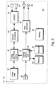
- FIG. 5 shows a simplified block diagram of a radio communication unit taking the form of a radio telephone set operating in accordance with the present invention.
- DECT Digital Enhanced Cordless Telecommunications
- MC/TDMA/TDD Multi Carrier/Time Division Multiple Access/Time Division Duplex
- FIG. 1 illustrates a typical DECT radio communication system, generally designated with reference numeral 1.
- the system comprises three essential elements: a Radio Exchange (RE) 2, a number of compact Radio Access Units (RAU) or radio base stations 3, 4, 5 which are installed throughout the area to be covered and connect to the RE 2, and a plurality of remote cordless of wireless radio communication units taking the form of portable radio telephones or handsets 6, 7, 8 which connect by a radio link 10 to the RAU 3, 4, 5.
- RE Radio Exchange
- RAU Radio Access Units
- RAU Radio Access Units
- Each RAU 3, 4, 5 provides service to a given area, called a cell.
- the RAU 3, 4, 5 are positioned such that cells surround and/or overlap each other, i.e. a so-called multi-cell approach.
- the radius of indoor cells amounts typically from 10 m-100 m, whereas the radius of outdoor cells typical ranges from 200 m up to 5000 m.
- the radio exchange 2 connects to a wired exchange 12 providing service to a plurality of wired telephones 14.
- the wired exchange 12 is generally a so-called Private Branch eXchange (PBX).
- PBX Private Branch eXchange
- the RE 2 connects to a Local Exchange (LE) of a public radio telecommunication network, such as the Public Switched Telephone Network (PSTN) 13, i.e. the ordinary wired public telephone network.
- PSTN Public Switched Telephone Network
- the RAU 3, 4, 5 connect by a radio air link 10 to a so-called Fixed Access Units (FAU) 9 which, in fixed RLL, connects to a fixed telephone terminal or socket for the connection of an ordinary wired telephone 15.
- FAU 9 is arranged to establish a radio air link with a handset in the home 11 (not shown).
- the information over the radio air link 10 is transmitted using a frame structure shown in figure 2.
- the remote radio communication units such as the handset 6, 7, 8 or FAU 9
- the remote radio communication units transmit data to the RAU.
- a radio communication link between a RAU and a remote radio communication unit is assigned a time slot in the first half of the frame and a time slot bearing the same number in the second half of the frame.
- Each time slot or burst forms a radio communication channel and typically contains control data, system data and information or user data.
- DECT does not provide a separate signalling channel.
- Signalling information concerning identity and access rights, service availability and, if applicable, information for handover to another radio communication channel in case of disturbances (internal handover) or transfer of a call to another radio access unit (external handover) is transmitted in the system data field of each time slot. Also paging data and call set up data are exchanged in the system data field.
- the control data field contains a so-called synchronization (SYNC) word, which has to be correctly identified at a RAU and a remote radio communication unit in order to process the received data.
- SYNC synchronization
- the information or user data is transmitted in the user data field, having a typical bit rate of 32 kb/s.
- Figure 3a illustrates a present radio communication method following the DECT protocol.
- TB Traffic Bearer
- remote communication unit 8 is assumed to listen to RAU 4 at communication channel R3 for synchronization and signalling purposes. (See also figure 1). Non-occupied radio channels are indicated by "--”.
- Remote communication unit 8 which is receiving radio channel or time slot R3 for synchronization and signalling purposes, now has to search for another radio channel or time slot in order not to loose its connection to RAU 4.
- searching for another radio channel in particular if to be performed at a relatively fast scanning rate, consumes battery power.
- DECT for example, if no information of a RAU is received, a remote communication unit will indicate an "out of range" message or signal. If such signal or message is frequently provided, the user of the radio communication unit may not justified assume malfunctioning of the radio communication unit or the system as a whole.
- Figure 3b shows the improvement following the method according to the invention.
- a so-called "Dummy Bearer" DB is established at radio communication channel or time slot R3, providing channel information pointing to another active and available radio channel or time slot for receipt of synchronization and signalling information.
- the DB at radio channel R3 refers to the active TB at radio channel R9.
- Remote radio communication unit 8 which is receiving radio channel or time slot R3, now does not have to perform a search for another active or available TB, but can instead directly switch to the radio channel or time slot R9 as indicated by the DB at radio channel or time slot R3. Accordingly, no scarce battery power has to be used for scanning the radio links 10 and, because the actual change of radio channel can be performed in one frame, no calls or messages will be missed by the radio communication unit 8.
- a radio communication unit may be in an idle or "Normal Duty Cycle” mode, wherein information is received once in a "multiframe”, which equals 16 frames of 24 time slots, or in a "Low Duty Cycle” mode receiving information once in four multiframes.
- the DB established after the termination of a TB at a particular radio channel or time slot is kept for 64 frames or 4 multiframes, i.e. up to and including frame N+64.
- a DB transmitted after the release of a TB at a particular communication channel prevents this channel from being used by another radio communication link or TB.
- the maximum number of DB is time-related, i.e. the interval wherein DBs occur. Priority is given to "new" DB over "old" DB.
- the channel information or DB according to the invention is transmitted each time an active TB is terminated, thus also at the end of a call, for example.
- FIG. 4 shows a block diagram of a RAU 20 operating in accordance with an embodiment of the present invention following the DECT protocol.
- the RAU 20 has a wired connection 21 to an RE 2, shown in figure 1.
- Central control and application logic 22 detects incoming calls and controls outgoing calls and selects suitable combination of carriers and time slots. The several connections and time slots are merged by a multiplexer 23.
- the RAU 20 has a frame and slot synchronization unit 24 which controls slot reception and transmission timing.
- the central control logic 22 also controls a Transmit/Receive (T/R) switch 25 and an antenna diversity switch 26, if antenna diversity is implemented.
- T/R Transmit/Receive
- the radio interface of the access unit 20 consists of a receiver/demodulator 27 and a transmitter/modulator 28. Synchronization and control information is stripped from received data by unit 29, whereas such information is added to the data to be transmitted by unit 30, connected as shown.
- the frame and slot synchronization unit 24 is controlled to transmit channel information as indicated by block 31.
- Block 31 may be implemented in hardware and/or software.
- Figure 5 shows a simplified block diagram of a radio telephone set 40, arranged for switching of reception following the receipt of channel information in accordance with the present invention.
- the radio telephone set 40 comprises four essential building blocks, i.e. a central control and application unit 41, a radio unit 42, a timing and synchronization (SYNC) control unit 43 and a speech processing unit 44.
- a central control and application unit 41 a radio unit 42
- a timing and synchronization (SYNC) control unit 43 a speech processing unit 44.
- SYNC timing and synchronization
- the radio unit 42 comprises an air interface 45 having an antenna system coupled to a transceiver unit comprising a transmitter/modulator and a receiver/demodulator (not shown).
- the timing and synchronization control unit 43 receives data over the air interface 45 and the radio unit 42. Signalling and synchronization information are removed from the received data by the unit 43 and the received speech data are fed to the speech processing unit 44.
- the speech processing unit 44 takes care of the encryption of received data.
- a codec 46 decodes the received digital speech data into analog form for making it audible to a user of the handset by a loudspeaker 47 connected to the codec 46.
- Speech produced by the user is received by a microphone 48 and encoded into a suitable digital format by the codec 46.
- This encoded speech data is fed to the speech processing unit 44.
- the timing and synchronization control unit 43 adds suitable synchronization and signalling information to the encrypted speech data.
- the radio unit 42 transmits this signalling and speech data at the air interface 45 for reception by a RAU of the communication system to which the telephone set 40 is operatively connected. (See figure 1).
- the central control and application unit 41 comprises a microprocessor or microcontroller and memory means, and connects to the timing and synchronization control unit 43.
- the central control unit 41 essentially controls the system data and the connection with the user of the radio telephone set 40 by a keypad means 49, display means 53 and ring generator means 50, all connected to the central control unit 41. Further, an external interface 55 is provided which connects to the central control unit 41 for external control and data processing purposes.
- Frame and time slot allocation and, in the case of a multi-carrier, multi-time-slot technology such as DECT, also the various combinations of carrier frequencies and time slots are controlled by the central control unit 41.
- the ring generator means 50 connects to a buzzer 51 or vibrator (not shown) for producing a ringing or alerting sound at the arrival of a call.
- a visual alerting signal may be emitted by a lamp or Light Emitting Diode (LED) 52, connected as shown.
- the display means 53 such as an LCD device, are operatively connected to the central control unit 41 for displaying call information and other user and system data, such as the "Out of Range"-message.
- a battery and powering unit 54 is included for the overall powering of the telephone set 40 .
- the central control unit 41 is arranged to perform switching of the radio unit 42 to another radio communication channel in accordance with the channel information or DB received. To this end, the central control unit 41 is provided with suitable hardware and/or software as schematically indicated by block 56.
- present invention is generally illustrated with respect to DECT radio telephone communication system, it is not restricted thereto.
- the present invention can be used with other communication devices, such as data communication equipment as well as in other wireless multi-cell communication systems such as designated CT2 and PHS, for example.
Landscapes
- Engineering & Computer Science (AREA)
- Computer Networks & Wireless Communication (AREA)
- Signal Processing (AREA)
- Mobile Radio Communication Systems (AREA)
Claims (9)
- Procédé de communication par radio dans un système de communication par radio (1) comprenant des unités d'accès de radio (3, 4, 5) et des unités de communication par radio à distance (6, 7, 8, 9), dans lequel une liaison de communication (10) entre une unité d'accès de radio (3, 4, 5) et une unité de communication par radio (6, 7, 8, 9) est établie sur un canal de communication par radio d'une pluralité de canaux de communication par radio disponibles (R1, ..., R12 ; T1, ..., T12), et dans lequel une information de canal est transmise par ladite unité d'accès de radio (3, 4, 5), se référant à un canal de communication par radio, caractérisé en ce qu'immédiatement après l'achèvement d'une liaison de communication (10) sur un canal de communication par radio, une information de canal est transmise par ladite unité d'accès de radio (3, 4, 5) sur ledit canal de communication par radio auquel il est fait référence (16), à un autre canal de communication par radio sur lequel l'information est transmise.
- Procédé selon la revendication 1, dans lequel le nombre de canaux de communication par radio transmettant une information de canal simultanément est limité à une valeur prédéterminée.
- Procédé selon la revendication 2, dans lequel de nouvelles transmissions d'information de canal reçoivent une priorité par rapport à des transmissions en cours d'information de canal.
- Procédé selon l'une quelconque des revendications précédentes, dans lequel une information est transmise selon un mode d'accès multiple par division dans le temps (TDMA), comprenant des trames transmises de façon répétée de canaux de communication du type à salves multiples (R1, ..., R12 ; T1, ..., T12), dans lequel ladite information de canal est transmise durant une pluralité de salves successives.
- Procédé selon l'une quelconque des revendications précédentes, dans lequel ladite communication par radio fonctionne selon le protocole de télécommunications sans fil améliorées numériques (Digital Enhanced Cordless Telecommunications ou DECT), dans lequel ladite information de canal est transmise sous la forme de ce que l'on appelle une "porteuse fictive" ("Dummy Bearer" ou DB), et comprend ce que l'on appelle un message "autre porteuse recommandée" ("Recommended Other Bearer" ou ROB), dans lequel "porteuse" désigne un canal de communication par radio du type à salves.
- Procédé selon la revendication 5, dans lequel le nombre de porteuses fictives (DB) fonctionnant simultanément est limité à une valeur qui est égale à deux ou trois.
- Procédé selon la revendication 5 ou 6, dans lequel une porteuse fictive (DB) après l'achèvement d'un canal de communication par radio ou "une porteuse de trafic" ("Traffic Bearer" ou TB) est transmise dans chaque trame parmi quatre trames multiples, et chaque trame multiple comprend seize trames à accès multiple par division dans le temps.
- Procédé selon l'une quelconque des revendications précédentes, dans lequel des unités de communication par radio à distance (6, 7, 8, 9) recevant ladite information de canal sur un canal de communication par radio suspendent la réception sur ledit canal de communication par radio et reprennent la réception sur un canal de communication par radio auquel il est fait référence (16) par ladite information de canal.
- Unité d'accès de radio (20) comprenant des moyens formant émetteur/récepteur (27, 28) et des moyens de commande (24) pour commander l'émission et la réception sur une pluralité de canaux de communication par radio, caractérisée en ce que lesdits moyens de commande (24) sont agencés (31) pour transmettre une information de canal sur un canal de communication par radio immédiatement après l'achèvement d'une liaison de communication (10) sur ledit canal de communication par radio auquel il est fait référence (16), à un autre canal de communication par radio sur lequel l'information est transmise.
Priority Applications (2)
| Application Number | Priority Date | Filing Date | Title |
|---|---|---|---|
| DE69722228T DE69722228T2 (de) | 1997-12-31 | 1997-12-31 | Ubertragung von Kanalinformation in einem Funkübertragungssystem |
| EP97204145A EP0930794B1 (fr) | 1997-12-31 | 1997-12-31 | Transmission des données sur des canaux dans un système de radiocommunication |
Applications Claiming Priority (1)
| Application Number | Priority Date | Filing Date | Title |
|---|---|---|---|
| EP97204145A EP0930794B1 (fr) | 1997-12-31 | 1997-12-31 | Transmission des données sur des canaux dans un système de radiocommunication |
Publications (2)
| Publication Number | Publication Date |
|---|---|
| EP0930794A1 EP0930794A1 (fr) | 1999-07-21 |
| EP0930794B1 true EP0930794B1 (fr) | 2003-05-21 |
Family
ID=8229148
Family Applications (1)
| Application Number | Title | Priority Date | Filing Date |
|---|---|---|---|
| EP97204145A Expired - Lifetime EP0930794B1 (fr) | 1997-12-31 | 1997-12-31 | Transmission des données sur des canaux dans un système de radiocommunication |
Country Status (2)
| Country | Link |
|---|---|
| EP (1) | EP0930794B1 (fr) |
| DE (1) | DE69722228T2 (fr) |
Families Citing this family (3)
| Publication number | Priority date | Publication date | Assignee | Title |
|---|---|---|---|---|
| KR20090072752A (ko) * | 2007-12-28 | 2009-07-02 | 엘지노텔 주식회사 | Dect 시스템의 베이스 스테이션 및 그의 무선 채널용량 확장 방법 |
| EP2418893B1 (fr) * | 2010-08-09 | 2018-11-21 | Lantiq Beteiligungs-GmbH & Co.KG | Procédé pour la transmission d'une porteuse du type "dummy" ("dummy bearer") dans un système DECT |
| EP2587698A1 (fr) * | 2011-10-28 | 2013-05-01 | Lantiq Deutschland GmbH | Mode veille pour transmission de données à base de trames |
Family Cites Families (3)
| Publication number | Priority date | Publication date | Assignee | Title |
|---|---|---|---|---|
| US5603081A (en) * | 1993-11-01 | 1997-02-11 | Telefonaktiebolaget Lm Ericsson | Method for communicating in a wireless communication system |
| FR2710805B1 (fr) * | 1993-09-29 | 1995-11-10 | Alcatel Mobile Comm France | Structure de burst de remplissage dans un système cellulaire de radiocommunications numériques utilisant le principe de l'AMRT, et station de base pour l'élaboration d'une telle structure. |
| DE19640450C1 (de) * | 1996-09-30 | 1997-10-30 | Siemens Ag | Basisstation mit schneller Kanalwechselfunktion eines zellularen TDMA/FDMA-Funksystems, insbesondere eines zellularen DECT-Systems |
-
1997
- 1997-12-31 DE DE69722228T patent/DE69722228T2/de not_active Expired - Lifetime
- 1997-12-31 EP EP97204145A patent/EP0930794B1/fr not_active Expired - Lifetime
Also Published As
| Publication number | Publication date |
|---|---|
| DE69722228T2 (de) | 2003-11-27 |
| DE69722228D1 (de) | 2003-06-26 |
| EP0930794A1 (fr) | 1999-07-21 |
Similar Documents
| Publication | Publication Date | Title |
|---|---|---|
| CA2232693C (fr) | Procede d'execution d'une commutation et d'une localisation dans un environnement de radiocommunications | |
| KR100378320B1 (ko) | 광역 셀룰러망 및 개인용 무선통신망으로부터 입중계 호출을 동시에 수신하는 방법 및 이동단말기 | |
| US5953323A (en) | Method and apparatus for adapting non-cellular private radio systems to be compatible with cellular mobile phones | |
| CA2025228C (fr) | Porteur pour balise | |
| US5726981A (en) | Methods for making active channel measurements in a personal base station environment | |
| EP0786174B1 (fr) | Synchronisation d'une connexion de telecommunication dans un systeme de communication mobile | |
| JPH0472828A (ja) | 移動無線通信システム | |
| WO1994008432A1 (fr) | Canal de commande numerique | |
| EP0961512A1 (fr) | Procédé de transfert dans un environment de radio-communication | |
| JPH0472831A (ja) | 無線通信方式 | |
| GB2227143A (en) | Mobile radio-telephone system with mobile units and base stations | |
| CN101647263B (zh) | 在通信系统与附属通信系统、数字储存媒体、计算机程序产品与计算机程序内建立使用者信道连接的控制装置及方法 | |
| EP0930794A1 (fr) | Transmission des données sur des canaux dans un système de radiocommunication | |
| US6138035A (en) | Mobile communication system having cordless handy phone unit as mobile station | |
| JP7748610B2 (ja) | コードレス電話装置の基地局、およびコードレス電話装置 | |
| JP3790065B2 (ja) | 通信用チャネル制御方法 | |
| JP7795702B2 (ja) | コードレス電話装置の基地局、コードレス電話装置の基地局および子機、およびコードレス電話システムの電話制御装置および基地局 | |
| JP3177581B2 (ja) | 無線チャネル設定制御方式 | |
| EP1410670B1 (fr) | Procede et dispositif de selection d'une unite d'acces par radio dans un systeme de radio communications | |
| JPS5934019B2 (ja) | 移動無線電話方式 | |
| KR100562386B1 (ko) | 무선 전화 시스템, 데이터 송신 방법 및 베이스 유닛 | |
| JPH03191623A (ja) | 移動体通信システムにおける無線ゾーン切替方法 | |
| JP2000115066A (ja) | Tdmaディジタル無線通信による一斉通報システム | |
| JPH0918406A (ja) | ディジタルコードレス電話システム | |
| JP2000115068A (ja) | Tdmaディジタル無線通信による一斉通報システム |
Legal Events
| Date | Code | Title | Description |
|---|---|---|---|
| PUAI | Public reference made under article 153(3) epc to a published international application that has entered the european phase |
Free format text: ORIGINAL CODE: 0009012 |
|
| AK | Designated contracting states |
Kind code of ref document: A1 Designated state(s): CH DE DK ES FR GB IT LI NL SE |
|
| AX | Request for extension of the european patent |
Free format text: AL;LT;LV;MK;RO;SI |
|
| 17P | Request for examination filed |
Effective date: 19991119 |
|
| AKX | Designation fees paid |
Free format text: CH DE DK ES FR GB IT LI NL SE |
|
| 17Q | First examination report despatched |
Effective date: 20000307 |
|
| GRAH | Despatch of communication of intention to grant a patent |
Free format text: ORIGINAL CODE: EPIDOS IGRA |
|
| GRAH | Despatch of communication of intention to grant a patent |
Free format text: ORIGINAL CODE: EPIDOS IGRA |
|
| GRAA | (expected) grant |
Free format text: ORIGINAL CODE: 0009210 |
|
| AK | Designated contracting states |
Designated state(s): CH DE DK ES FR GB IT LI NL SE |
|
| PG25 | Lapsed in a contracting state [announced via postgrant information from national office to epo] |
Ref country code: NL Free format text: LAPSE BECAUSE OF FAILURE TO SUBMIT A TRANSLATION OF THE DESCRIPTION OR TO PAY THE FEE WITHIN THE PRESCRIBED TIME-LIMIT Effective date: 20030521 Ref country code: LI Free format text: LAPSE BECAUSE OF FAILURE TO SUBMIT A TRANSLATION OF THE DESCRIPTION OR TO PAY THE FEE WITHIN THE PRESCRIBED TIME-LIMIT Effective date: 20030521 Ref country code: IT Free format text: LAPSE BECAUSE OF FAILURE TO SUBMIT A TRANSLATION OF THE DESCRIPTION OR TO PAY THE FEE WITHIN THE PRESCRIBED TIME-LIMIT;WARNING: LAPSES OF ITALIAN PATENTS WITH EFFECTIVE DATE BEFORE 2007 MAY HAVE OCCURRED AT ANY TIME BEFORE 2007. THE CORRECT EFFECTIVE DATE MAY BE DIFFERENT FROM THE ONE RECORDED. Effective date: 20030521 Ref country code: FR Free format text: LAPSE BECAUSE OF FAILURE TO SUBMIT A TRANSLATION OF THE DESCRIPTION OR TO PAY THE FEE WITHIN THE PRESCRIBED TIME-LIMIT Effective date: 20030521 Ref country code: CH Free format text: LAPSE BECAUSE OF FAILURE TO SUBMIT A TRANSLATION OF THE DESCRIPTION OR TO PAY THE FEE WITHIN THE PRESCRIBED TIME-LIMIT Effective date: 20030521 |
|
| REG | Reference to a national code |
Ref country code: GB Ref legal event code: FG4D |
|
| REG | Reference to a national code |
Ref country code: CH Ref legal event code: EP |
|
| REF | Corresponds to: |
Ref document number: 69722228 Country of ref document: DE Date of ref document: 20030626 Kind code of ref document: P |
|
| PG25 | Lapsed in a contracting state [announced via postgrant information from national office to epo] |
Ref country code: SE Free format text: LAPSE BECAUSE OF FAILURE TO SUBMIT A TRANSLATION OF THE DESCRIPTION OR TO PAY THE FEE WITHIN THE PRESCRIBED TIME-LIMIT Effective date: 20030821 Ref country code: DK Free format text: LAPSE BECAUSE OF FAILURE TO SUBMIT A TRANSLATION OF THE DESCRIPTION OR TO PAY THE FEE WITHIN THE PRESCRIBED TIME-LIMIT Effective date: 20030821 |
|
| PG25 | Lapsed in a contracting state [announced via postgrant information from national office to epo] |
Ref country code: ES Free format text: LAPSE BECAUSE OF FAILURE TO SUBMIT A TRANSLATION OF THE DESCRIPTION OR TO PAY THE FEE WITHIN THE PRESCRIBED TIME-LIMIT Effective date: 20030901 |
|
| NLV1 | Nl: lapsed or annulled due to failure to fulfill the requirements of art. 29p and 29m of the patents act | ||
| REG | Reference to a national code |
Ref country code: CH Ref legal event code: PL |
|
| PLBE | No opposition filed within time limit |
Free format text: ORIGINAL CODE: 0009261 |
|
| STAA | Information on the status of an ep patent application or granted ep patent |
Free format text: STATUS: NO OPPOSITION FILED WITHIN TIME LIMIT |
|
| RAP2 | Party data changed (patent owner data changed or rights of a patent transferred) |
Owner name: TELEFONAKTIEBOLAGET LM ERICSSON (PUBL) |
|
| 26N | No opposition filed |
Effective date: 20040224 |
|
| EN | Fr: translation not filed | ||
| PGFP | Annual fee paid to national office [announced via postgrant information from national office to epo] |
Ref country code: GB Payment date: 20161228 Year of fee payment: 20 |
|
| PGFP | Annual fee paid to national office [announced via postgrant information from national office to epo] |
Ref country code: DE Payment date: 20161229 Year of fee payment: 20 |
|
| REG | Reference to a national code |
Ref country code: DE Ref legal event code: R071 Ref document number: 69722228 Country of ref document: DE |
|
| REG | Reference to a national code |
Ref country code: GB Ref legal event code: PE20 Expiry date: 20171230 |
|
| PG25 | Lapsed in a contracting state [announced via postgrant information from national office to epo] |
Ref country code: GB Free format text: LAPSE BECAUSE OF EXPIRATION OF PROTECTION Effective date: 20171230 |