EP0931233B1 - Selbsteinstellbarer schlauch aus mindestens zweifach orientiertem polymer und rohrklemme - Google Patents
Selbsteinstellbarer schlauch aus mindestens zweifach orientiertem polymer und rohrklemme Download PDFInfo
- Publication number
- EP0931233B1 EP0931233B1 EP97911790A EP97911790A EP0931233B1 EP 0931233 B1 EP0931233 B1 EP 0931233B1 EP 97911790 A EP97911790 A EP 97911790A EP 97911790 A EP97911790 A EP 97911790A EP 0931233 B1 EP0931233 B1 EP 0931233B1
- Authority
- EP
- European Patent Office
- Prior art keywords
- hose
- clamp
- diameter
- temperatures
- band
- Prior art date
- Legal status (The legal status is an assumption and is not a legal conclusion. Google has not performed a legal analysis and makes no representation as to the accuracy of the status listed.)
- Expired - Lifetime
Links
- 229920000642 polymer Polymers 0.000 title claims description 51
- 239000002826 coolant Substances 0.000 claims description 19
- 230000004044 response Effects 0.000 claims description 12
- 238000000034 method Methods 0.000 claims description 5
- 238000004519 manufacturing process Methods 0.000 claims description 2
- 238000007789 sealing Methods 0.000 claims description 2
- 239000000463 material Substances 0.000 description 42
- 239000012530 fluid Substances 0.000 description 14
- 230000003068 static effect Effects 0.000 description 11
- 230000008878 coupling Effects 0.000 description 8
- 238000010168 coupling process Methods 0.000 description 8
- 238000005859 coupling reaction Methods 0.000 description 8
- LYCAIKOWRPUZTN-UHFFFAOYSA-N Ethylene glycol Chemical compound OCCO LYCAIKOWRPUZTN-UHFFFAOYSA-N 0.000 description 6
- 238000009434 installation Methods 0.000 description 6
- 239000002861 polymer material Substances 0.000 description 6
- 230000008602 contraction Effects 0.000 description 5
- 238000000926 separation method Methods 0.000 description 5
- 239000003502 gasoline Substances 0.000 description 4
- 229910052751 metal Inorganic materials 0.000 description 4
- 239000002184 metal Substances 0.000 description 4
- 230000005540 biological transmission Effects 0.000 description 3
- 230000006835 compression Effects 0.000 description 3
- 238000007906 compression Methods 0.000 description 3
- 230000006378 damage Effects 0.000 description 3
- 230000000694 effects Effects 0.000 description 3
- 239000010705 motor oil Substances 0.000 description 3
- 239000000126 substance Substances 0.000 description 3
- 208000027418 Wounds and injury Diseases 0.000 description 2
- 229910052782 aluminium Inorganic materials 0.000 description 2
- XAGFODPZIPBFFR-UHFFFAOYSA-N aluminium Chemical compound [Al] XAGFODPZIPBFFR-UHFFFAOYSA-N 0.000 description 2
- 230000007797 corrosion Effects 0.000 description 2
- 238000005260 corrosion Methods 0.000 description 2
- 230000007812 deficiency Effects 0.000 description 2
- 238000009826 distribution Methods 0.000 description 2
- 230000001747 exhibiting effect Effects 0.000 description 2
- 238000010438 heat treatment Methods 0.000 description 2
- 230000006872 improvement Effects 0.000 description 2
- 208000014674 injury Diseases 0.000 description 2
- 230000008569 process Effects 0.000 description 2
- 238000003860 storage Methods 0.000 description 2
- 239000002699 waste material Substances 0.000 description 2
- 229910000838 Al alloy Inorganic materials 0.000 description 1
- 229920001634 Copolyester Polymers 0.000 description 1
- 229910000831 Steel Inorganic materials 0.000 description 1
- 239000011324 bead Substances 0.000 description 1
- 230000002301 combined effect Effects 0.000 description 1
- 238000001816 cooling Methods 0.000 description 1
- 229920001577 copolymer Polymers 0.000 description 1
- 238000005520 cutting process Methods 0.000 description 1
- 230000001351 cycling effect Effects 0.000 description 1
- 230000001419 dependent effect Effects 0.000 description 1
- 229920001971 elastomer Polymers 0.000 description 1
- 239000000806 elastomer Substances 0.000 description 1
- 230000007613 environmental effect Effects 0.000 description 1
- 239000000446 fuel Substances 0.000 description 1
- 239000002654 heat shrinkable material Substances 0.000 description 1
- 239000007788 liquid Substances 0.000 description 1
- 230000007774 longterm Effects 0.000 description 1
- 239000000314 lubricant Substances 0.000 description 1
- 238000002844 melting Methods 0.000 description 1
- 230000008018 melting Effects 0.000 description 1
- 238000012986 modification Methods 0.000 description 1
- 230000004048 modification Effects 0.000 description 1
- 239000003921 oil Substances 0.000 description 1
- 230000002085 persistent effect Effects 0.000 description 1
- 230000002035 prolonged effect Effects 0.000 description 1
- 230000009467 reduction Effects 0.000 description 1
- 239000010959 steel Substances 0.000 description 1
- 239000002023 wood Substances 0.000 description 1
Images

Classifications
-
- F—MECHANICAL ENGINEERING; LIGHTING; HEATING; WEAPONS; BLASTING
- F16—ENGINEERING ELEMENTS AND UNITS; GENERAL MEASURES FOR PRODUCING AND MAINTAINING EFFECTIVE FUNCTIONING OF MACHINES OR INSTALLATIONS; THERMAL INSULATION IN GENERAL
- F16L—PIPES; JOINTS OR FITTINGS FOR PIPES; SUPPORTS FOR PIPES, CABLES OR PROTECTIVE TUBING; MEANS FOR THERMAL INSULATION IN GENERAL
- F16L47/00—Connecting arrangements or other fittings specially adapted to be made of plastics or to be used with pipes made of plastics
- F16L47/20—Connecting arrangements or other fittings specially adapted to be made of plastics or to be used with pipes made of plastics based principally on specific properties of plastics
- F16L47/22—Connecting arrangements or other fittings specially adapted to be made of plastics or to be used with pipes made of plastics based principally on specific properties of plastics using shrink-down material
-
- B—PERFORMING OPERATIONS; TRANSPORTING
- B29—WORKING OF PLASTICS; WORKING OF SUBSTANCES IN A PLASTIC STATE IN GENERAL
- B29C—SHAPING OR JOINING OF PLASTICS; SHAPING OF MATERIAL IN A PLASTIC STATE, NOT OTHERWISE PROVIDED FOR; AFTER-TREATMENT OF THE SHAPED PRODUCTS, e.g. REPAIRING
- B29C61/00—Shaping by liberation of internal stresses; Making preforms having internal stresses; Apparatus therefor
- B29C61/06—Making preforms having internal stresses, e.g. plastic memory
- B29C61/08—Making preforms having internal stresses, e.g. plastic memory by stretching tubes
-
- Y—GENERAL TAGGING OF NEW TECHNOLOGICAL DEVELOPMENTS; GENERAL TAGGING OF CROSS-SECTIONAL TECHNOLOGIES SPANNING OVER SEVERAL SECTIONS OF THE IPC; TECHNICAL SUBJECTS COVERED BY FORMER USPC CROSS-REFERENCE ART COLLECTIONS [XRACs] AND DIGESTS
- Y10—TECHNICAL SUBJECTS COVERED BY FORMER USPC
- Y10S—TECHNICAL SUBJECTS COVERED BY FORMER USPC CROSS-REFERENCE ART COLLECTIONS [XRACs] AND DIGESTS
- Y10S285/00—Pipe joints or couplings
- Y10S285/906—Equivalents
-
- Y—GENERAL TAGGING OF NEW TECHNOLOGICAL DEVELOPMENTS; GENERAL TAGGING OF CROSS-SECTIONAL TECHNOLOGIES SPANNING OVER SEVERAL SECTIONS OF THE IPC; TECHNICAL SUBJECTS COVERED BY FORMER USPC CROSS-REFERENCE ART COLLECTIONS [XRACs] AND DIGESTS
- Y10—TECHNICAL SUBJECTS COVERED BY FORMER USPC
- Y10S—TECHNICAL SUBJECTS COVERED BY FORMER USPC CROSS-REFERENCE ART COLLECTIONS [XRACs] AND DIGESTS
- Y10S285/00—Pipe joints or couplings
- Y10S285/909—Fluorocarbons and memory plastics
Definitions
- the present invention relates generally to the clamping of elastomeric hose and tubing to fixtures and hose coupling devices, such as stems and coupling inserts, and to the use of bands formed from an at-least-twice-oriented polymer having a shrinkage response to each of at least two diameter reducing release temperatures, to provide improved constrictive forces about elastomeric hose and tubing. More particularly, this invention relates to an improved elastomeric hose and tubing clamp formed from a band of an at-least-twice-oriented polymer, which is simpler to install than prior art clamps. Specifically, this invention relates to an improved clamp for sealing hose and tubing to coupling devices associated with automotive coolant systems.
- hose Reinforced elastomeric hose and tubing, hereinafter generically referred to as hose, are commonly used to convey various fluids which may be under a variety of pressures and temperatures as part of fluid transport systems.
- connections between the hose and the stems, couplings or other fixtures must be fluid tight and must be able to resist separations caused by fluid pressure. This mode of separation is known as blow-off. Separation of the hose from the fixtures may also occur as a result of environmental interference, which mode of separation is known as pull-off.
- connections between hose and couplings or other fixtures are commonly made by placing the open end of a hose over e.g., a stem.
- the hose and the associated fixture are ordinarily sized and shaped to allow the open end of the hose to slip over the fixture, and to securely seat about same. In moderate temperature or pressure environments such a fit is generally sufficient. More typically however, a hose clamp is applied about the hose near the open end thereof for urging the hose more tightly about the stem or insert in order to resist leakage, blow-off and pull-off.
- Hose clamps have been produced in various sizes and shapes, and have been made of various materials. A number of prior art hose clamp designs, along with summaries of their respective deficiencies, are described in U.S. Patent No. 5,340,167. Common deficiencies of prior art hose clamps include the corrosion of metal clamps, the danger of hose damage due to sharp metal edges, clamp protrusions necessitating specific axial and circumferential placement of the clamp and occupying valuable space in the hose environment, and the difficulty in utilizing rapid automated assembly line-type installation techniques with these clamps. Additionally, most prior art hose clamps have insufficient self-adjustment characteristics, that is, an inability to expand and contract to follow the expansion and contraction of the clamped materials.
- dynamic hoop stress will be used to signify the constrictive force per unit area a hose clamp exerts upon the clamped object as a result of the inner diameter of the clamp being actively reduced.
- static hoop stress will be used to signify the constrictive force per unit area the clamp exerts upon the clamped object in countering an expansive force exerted by the clamped object. This is typically attributable to the fluid pressure present during fluid transfer, and also includes the effect of the thermal expansion of the elastomeric hose about which the band is clamped.
- the dynamic and static hoop stresses required of a particular clamp depend upon the application requirements.
- the heat shrinkable polymer hose clamp offers significantly improved self-adjustment characteristics and excellent dynamic and static hoop stresses for improved resistance to blow-off and pull-off compared to other more traditional styles of hose clamp, and it is furthermore devoid of projections which otherwise waste space, require specific axial or rotational positioning, and are a source of injury or the collection of debris.
- This type of clamp also conforms well to irregularities in stem and insert shapes. installation of the clamp however, requires the relatively cumbersome and awkward use of a heat source at the installation site to induce engagement of the clamp with the hose connection end. This is especially difficult in assembly-line type environments where different types of hose connection systems may be installed on automotive equipment.
- hose connection systems may be configured in a variety of directions, e.g., horizontally and vertically; they may come in an array of diameters; they may be located in relatively confined, tight areas surrounded by other equipment.
- heat must be applied for a period of time sufficient for proper engagement of the clamp and the hose; this may require from several seconds to several minutes depending on the clamp size and location, which operation is time-consuming and generally impractical in assembly line settings.
- the heat shrinkable band is moreover highly sensitive to operator error; if heat is not applied uniformly, the band may not fit correctly, resulting in increased potential for leakage. To ensure uniform heat distribution, the use of a device or heat monitor may be required. Likewise, if the clamp is not applied in the correct position, perfect heat distribution may not compensate for misfit which also increases the possibility of leakage.
- a hose clamp that is self-adjusting, is capable of exhibiting a uniform constrictive force about the connection end of hose, is capable of improved dynamic and static hoop stresses, and which may be applied to hose connection ends easily and without the external application of heat has not heretofore been known.
- hose clamp which is capable of being rapidly installed about the connection ends of hose and tubing without the need for the application of heat to the clamp.
- an oriented polymer type hose clamp as defined in claim 1, appended hereto.
- This clamp may be a self-adjusting, at-least-twice-oriented polymer hose clamp.
- the present invention further provides a method for producing the hose clamp.
- the hose clamp of the present invention provides a clamping force about a connection end of elastomeric hose.
- the device includes an at-least-twice-oriented polymer band exhibiting a shrinkage response to each of at least two temperature reducing release temperatures, which polymer is formed into a band or clamp.
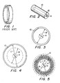
- FIG. I there is an example of an existing hose clamp, i.e., a heat-shrinkable hose and tubing clamp, the disadvantages of which, in terms of greater constrictive force and ease of effective installation over the connection ends of hose and tubing, the present invention is seen to be an improvement upon.
- a heat-shrinkable hose and tubing clamp i.e., a heat-shrinkable hose and tubing clamp
- FIG. 2 there is shown a preferred embodiment of the present invention in the form of a self-adjusting at-least-twice-oriented polymer hose and tubing clamp 10 in its non-oriented or pre-expanded state.
- at-least-twice-oriented polymer in this context is a polymer which has been oriented, i.e., mechanically expanded at least twice to result in a polymer which exhibits a shrinkage response to each of at least two diameter reducing release temperatures.
- the inside diameter A of the clamp 10 at this point is defined as its first nominal inside diameter. This diameter is generally smaller than the outside diameter of the connection end of the hose about which the clamp is to be applied.
- the clamp 10 may be formed by first extruding a tube of the clamp material with a bore 12, and cutting it to length as shown.
- the clamp is designed such that the ratio of the outside diameter of the hose about which the clamp will be placed, to the clamp's first nominal inside diameter is from about 2.5:1.0 to about 5.0:1.0, more preferably from about 3.0:1.0 to about 4.8:1.0, and is most preferably from about 3.5:1.0 to about 4.5:1.0.
- the lower modulus of the clamp material useful in the practice of the present invention compared to metal hose clamps of the prior art allows greater widths to be utilized; the clamp may extend over the bead of the stem without compromising the clamp's seal integrity.
- the homogeneity of the clamp material and continuity of the clamp design allow for greater clamp thicknesses. In metal hose clamps of the prior art, such thicknesses would generally result in leak paths.
- a hose clamp of the present invention designed for use with a conventional 2.5 inch (6.4 cm.) inside diameter elastomer hose will have a width of from approximately 1.20 inches (3.05 cm.) to approximately 1.40 inches (3.56 cm.) and a thickness of from approximately 0.080 inches (0.20 cm.) to about 0.100 inches (0.25 cm).
- a hose clamp of the present invention designed for use with a conventional 0.75 inch (1.91 cm.) inner diameter hose will have a width of from approximately 0.75 inches (1.90 cm) to about 0.94 inches (2.39 cm) and a thickness of from approximately 0.060 inches (0.15 cm) to about 0.080 inches (0.20 cm).
- the tube is then mechanically expanded for a first time at a preselected temperature, taking on the appearance depicted in FIG. 3 by solid lines.
- the clamp 10 has an inside diameter B that exists during an interim period after first polymer orientation but before second polymer orientation, which diameter is defined as the second nominal inside diameter.
- the second nominal inside diameter is generally also smaller than the outside diameter of the hose, but is greater than the clamp's first nominal inside diameter.
- This first mechanical expansion performs the first polymer orientation, which is the process of mechanically deforming the polymer material so as to generate stress characteristics within the polymer structure that result in a response to one of the two or more diameter reducing release temperatures.
- the stress release associated with this expansion step is manifested by the polymer material tending to reshape itself toward the shape it occupied prior to the first polymer orientation operation, i.e., to its first nominal inside diameter A, and takes place when the clamp is exposed to temperatures at or near the first mechanical expansion temperature.
- the first mechanical expansion is carried out such that the ratio of the clamp's second nominal inside diameter to its first nominal inside diameter is from about 1.5:1.0 to about 5.0:1.0, more preferably from about 2.5:1.0 to about 4.2:1.0, and is most preferably from about 3.0:1.0 to about 4.0:1.0.
- the polymer bands which form the hose clamps of the present invention respond to each of at least two diameter reducing release temperatures which preferably fall within the range of from about -40°C to about 175°C, exposure of the band to each of which cause the bands to tend to shrink.
- the diameter reducing release temperatures may be variably preselected. Each diameter reducing release temperature should preferably in such case be selected so that a distinct shrinkage phase occurs for each such temperature. That is, for a given band, each diameter reducing release temperature should preferably be at least about 5°C different from any other diameter reducing release temperature within the specified range.
- each of the mechanical expansion operations is preferably performed at temperatures below the melting points of the hose and stem material, but in any case above approximately -40°C, and preferably above -10°C, to generate the release characteristics useful in the present invention.
- the first mechanical expansion is preferably performed in the temperature range of from about 0°C to about 150°C, more preferably from about 15°C to about 100°C and most preferably from about 60°C to about 85°C. According to this embodiment, this first mechanical expansion operation performed at these relatively high temperature creates in the clamp its second of at least two diameter reducing release temperatures.
- the clamp may be temporarily set at its second nominal inside diameter by chilling it sufficiently, i.e., at from about 15°C to about -40°C, more preferably at from about 10°C to about -25°C, and most preferably at from about 5°C to about -20°C.
- the oriented band may optionally be mounted upon a restraint at this second nominal inside diameter to avoid any contraction that may be encountered. Any suitable material including cardboard is envisioned for such restraint, which may be generally circular in shape and have an outer diameter just smaller than the band's second nominal inside diameter to allow for placement of the band upon the restraint.
- the clamp is then mechanically expanded for a second time at a preselected temperature, taking on the appearance depicted in FIG. 4 by solid lines.
- the clamp 10 has an inside diameter C that exists during an interim period after second polymer orientation yet before either subsequent mechanical expansions, or application to and shrinkage about the connection end of hose.
- This diameter is defined as the third nominal inside diameter.
- the third nominal inside diameter is generally greater than the outside diameter of the hose.
- This second mechanical expansion comprises the second polymer orientation, which repeats the process of mechanically deforming the polymer material so as to generate additional stress characteristics within the polymer structure that result in a response to the second of the two or more diameter reducing release temperatures.
- the stress release associated with this expansion step is manifested by the polymer material tending to reshape itself toward the shape it occupied prior to the second polymer orientation operation, i.e., to its second nominal inside diameter B, and generally takes place when the clamp is exposed to temperatures at or near the temperature at which the second mechanical expansion took place.
- the second mechanical expansion is carried out such that the ratio of the third nominal inside diameter to the first nominal inside diameter is preferably from about 3.0:1.0 to about 6.0:1.0, more preferably from about 4.0:1.0 to about 5.5:1.0, and is most preferably from about 4.4:1.0 to about 5.2:1.0.
- the second mechanical expansion temperature is preferably in the range of from about 0°C to about 40°C, more preferably from about 10°C to about 30°C and most preferably from about 15°C to about 25°C. These ranges generally encompass what is commonly referred to as "room temperature". According to this embodiment, this second mechanical expansion operation performed at room temperature creates in the clamp its response characteristic to the first of at least two diameter reducing release temperatures.
- the at-least-twice-oriented polymer clamp may be mounted upon a generally circular sturdy restraint which resists the forces generated in the clamp which tend to reshape it into its respective pre-orientation diameters.
- An example of one such sturdy restraint is illustrated in FIG. 9, and comprises a sturdy band having either butted or stitched ends, which is formed into a circle or ring 20.
- the restraint whilst requiring sufficient strength to resist buckling via the band's generated compressive forces, must nevertheless be crushable to the extent that it can be buckled or crushed by the application of force from any radial direction by a suitable tool or by hand. This is necessary in order to allow for removal of the band from the restraint at the time of application.
- the band may be formed from any suitable durable material, including aluminum, steel, reinforced cardboard and wood, and in a preferred embodiment, is made of aluminum. The thickness of the ring will vary depending upon the dimensions of and the constrictive forces exerted by the oriented polymer clamp.
- the sturdy restraint is formed from a quarter hard or half hard slit edge aluminum alloy.
- the restraint preferably has a wall thickness of from about 0.010 inches (0.025 cm) to about 0.050 inches (0.13 cm), more preferably from about 0.015 inches (0.038 cm) to about 0.040 inches (0.10 cm), and most preferably from about 0.020 inches (0.051 cm) to about 0.035 inches (0.089 cm).
- the restraint preferably has a band width for these design parameters, of from about 0.500 inches (1.27 cm) to about 2.00 inches (5.08 cm), more preferably from about 0.55 inches (1.40 cm) to about 1.75 inches (4.45 cm), and most preferably from about 0.60 inches (1.52 cm) to about 1.60 inches (4.06 cm).
- the hose clamp 10 may be prepared for placement about the connection end of an elastomeric hose, for clamping the hose 14 to a stem or other hose insert 16, as depicted in FIG. 6.
- the stem or insert 16 may be associated with any fluid transport system. Such stems and inserts are more preferably associated with systems carrying liquids at temperatures in the range of from about -40°C through about 175°C. In a preferred embodiment, the stems and inserts are associated with automotive engine coolant systems.
- chilling prior to clamp application merely slows, but generally does not prevent shrinkage of the band.
- the clamp may begin to shrink substantially below its diameter reducing release temperature, but such shrinkage is at a much slower rate than that shrinkage which occurs when the clamp is exposed to temperatures at or near a preselected diameter reducing release temperature.
- the application of the clamp 10 to the connection point 18 of a hose and coupling assembly generally involves removing the clamp 10 from the sturdy restraint 20, placing the clamp 10 about the hose 14 at the hose's connection end 18, and placing the connection end 18 about the stem or insert 16.
- a lubricant may be applied to the hose and/or stem to facilitate application of the clamp. It is contemplated that installation of the at-least-twice-oriented polymer hose clamps will commonly be performed in a room temperature environment. In a preferred embodiment, the second mechanical expansion is performed at room temperature resulting in the clamp's response to the first diameter reducing release temperature.
- the clamp's fourth nominal inside diameter is the inner diameter the clamp assumes upon initial shrinkage about the connection end of the hose and stem at the clamp's first diameter reducing release temperature.
- the clamp's fourth nominal inside diameter is generally smaller than its third nominal inside diameter.
- the clamp is in place about the connection site, and, in a preferred embodiment associated with automotive coolant systems, coolant may now be transferred through the system, generally reaching temperatures of approximately 110°C.
- coolant may now be transferred through the system, generally reaching temperatures of approximately 110°C.
- the second diameter reducing release characteristic to cause the clamp to tend to further shrink to a point previously defined as the first nominal inside diameter A.
- the clamp is substantially prevented from reaching the first nominal inside diameter by the presence of the hose. Instead, the clamp at this point shrinks until reaching an inner diameter defined as its fifth nominal inside diameter.
- the clamp's fifth nominal inside diameter is the inner diameter of the clamp upon secondary shrinkage about the connection end of the hose and stem at the clamp's second diameter reducing release temperature.
- the first shrinkage phase has been found to be sufficient to generate dynamic hoop stress of about 500 psi (3.46 X 10 6 Pa) in a self-adjusting, at-least-twice-oriented polymer hose clamp designed for a 5/8-inch (1.59 cm) inside diameter hose, which in practice is sufficient for acceptable initial engagement of such clamp about hose connection ends.
- the application of heat is unnecessary to bring about sufficient shrinkage to set the clamp in a secure position about the connection end 18 as depicted in FIG. 5.
- the material of the clamp 10 is fairly flexible and the shape of the clamp is without significant discontinuities, it can be seen that the constrictive force applied by the clamp 10 at this point is substantially uniform.
- Table 1 lists respective nominal inside diameters of several preferred embodiments of the present invention, as well as the inner and outer diameters of the elastomeric hose for which each clamp is optimally designed. In the table, all values are given in inches, and;
- the ratio of the third nominal inside diameter of the band to the hose outside diameter is preferably from about 1.0:1.0 to about 1.5:1.0, more preferably from 1.05:1.00 to about 1.28:1.00, and is most preferably from about 1.10:1.00 to about 1.21:1.00.
- the ratio of the hose outside diameter to the second nominal inside diameter is preferably from about 1.0:1.0 to about 1.5:1.0, more preferably from about 1.05:1.0 to about 1.3:1.0, and is most preferably from about 1.1:1.0 to about 1.2:1.0.
- the ratio of the third nominal inside diameter of the band to the second nominal inside diameter of the band is preferably from about 1.05:1.0 to about 2.0:1.0, more preferably from about 1.1:1.0 to about 1.6:1.0, and is most preferably from about 1.2:1.0 to about 1.5:1.0.
- FIG. 7 Another preferred embodiment of the present invention is depicted in FIG. 7.
- the material of the clamp 10 is formed into a strip 10a.
- the strip is then stretched at least twice according to the procedure and factors previously described for polymer orientation to new oriented dimensions, 10b, 10c.
- the at-least-twice-oriented strip 10c is then folded back onto itself to form a band and the overlapped portion is chemically or otherwise welded, as depicted in solid lines for clamp 10d of FIG. 8.
- the application of the clamp 10d in this embodiment is the same as that for the previous embodiment.
- this embodiment introduces a discontinuity in the clamp 10 at the position where the strip overlaps, giving rise to a less uniform constrictive force than in the embodiment described earlier. Whether this reduction in uniformity provides an opportunity for leakage depends upon the particular clamp application.
- the characteristics of the material useful in the practice of the present invention and for the described embodiments are essentially the same.
- the material once having been subjected to successive mechanical stretching operations, possesses multiple diameter reducing release characteristics, or responses to multiple diameter reducing release temperatures which result in multiple shrinkage phases.
- the number of diameter reducing release characteristics is generally equal to the number of mechanical stretching operations the material has undergone.
- Each of the diameter reducing release characteristics may be preferably preselected for an intended application, within the given range, by selecting the temperature at which the material is maintained during polymer orientation. The temperature so chosen is the setting temperature.
- the temperature at which the clamp is mechanically expanded will generally but not necessarily be the temperature which will trigger a given shrinkage phase. This characteristic provides the clamp designer sufficient flexibility to design for a variety of different pressure and temperature applications, as well as a variety of conditions to which the clamp will be exposed during transport and storage.
- the clamp is formed from a material which preferably tends to shrink substantially every time it is subjected to temperatures at or above each of its respective release temperatures. This characteristic is hereinafter referred to as "tenacious shrinkage”. This is in contrast to those heat shrinkable materials which shrink only a few times or even just once to a limit defined by their environment, and then take a set, such that even if heated unrestrained in free space the material is not able to shrink multiple times. Tenacious shrinkage in the material preferred in the present invention occurs as long as the material is not permitted to shrink to a point corresponding to that which would result if the clamp, standing unrestrained in free space, was subjected to temperatures above its release temperatures for a prolonged period.
- the clamp would generally not be able to shrink every time it was exposed to its particular release temperatures. In actual practice however, the clamp is restrained from this type of substantial shrinkage, first by a sturdy restraint, and thereafter by the item being clamped.
- the material prepared and formed into a clamp is also preferably characterized by a combination of elasticity and a coefficient of thermal expansion such that the clamp expands under heating conditions and retracts under cooling conditions at a rate near or greater than that of the corresponding expansion and retraction of the materials on which the clamp acts, including the hose and underlying stem.
- the clamp is able to compensate for the effects of pressure, temperature and age upon the hose and stem due to its self-adjustment characteristic coupled with substantial uniformity of constrictive force and conformability to irregularities in stem and insert shapes. Hot leaks and cold leaks are thus substantially eliminated over the life of the clamp and the associated fluid transport system.
- dynamic hoop stress is the constrictive force per unit cross-sectional area of the band the clamp exerts upon the clamped object as a result of the inner diameter of the clamp being actively reduced. In this case, this is by the function of the individual shrinkage modes.
- Static hoop stress is the constrictive force per unit cross-sectional area of the band which the clamp exerts upon the clamped object in countering an expansive force exerted by the clamped object.
- the at-least-twice-oriented polymer hose clamp of the present invention there exist at least two dynamic hoop stress values and at least two static hoop stress values; one for each shrink mode.
- the static hoop stresses for the lower temperature shrink mode i.e., the clamp's first static hoop stress, however exist for a very short period, i.e., only for as long as the higher temperature fluid has not yet flowed through the connection point to trigger the second shrinkage mode.
- the dynamic hoop stress associated with the initial shrinkage mode i.e., the clamp's first dynamic hoop stress
- the clamp's first dynamic hoop stress is preferably from about 10 to about 3000 psi (6.89 X 10 4 to about 2.07 X 10 7 Pa); more preferably from about 100 to about 2000 psi (6.89 X 10 5 to about 1.38 X 10 7 Pa); and most preferably from about 500 to about 1500 psi (3.45 X 10 6 to about 1.03 X 10 7 Pa), all over the temperature range of -40°C through 175°C.
- the dynamic hoop stress associated with the second shrinkage mode i.e., the clamp's second dynamic hoop stress
- the static hoop stress for this secondary shrinkage mode is preferably from about 100 to about 5000 psi (6.89 X 10 5 to about 3.45 X 10 7 Pa); more preferably from about 800 to about 4500 psi (5.52 X 10 6 to about 3.10 X 10 7 Pa); and most preferably from about 1000 to about 3600 psi (6.89 X 10 6 to about 2.48 X 10 7 Pa), all over the temperature range of -40°C through 175°C.
- the material prepared and formed into a clamp is resistant to the common under hood chemicals, including ethylene glycol, gasoline, motor oil and automatic transmission fluids, Types A and F.
- Gasoline is defined as ASTM Reference Fuel C in ASTM D471-79.
- Motor Oil is defined as ASTM Oil No. 3 in ASTM D471-79.
- ASTM D471-79 is incorporated herein by reference.
- the preferred materials' resistance to these fluids is such that when the material is immersed in ethylene glycol and held at a temperature of 22°C for seven days, it retains 101 percent of its original tensile strength, 94 percent of its original elongation to break, 86 percent of its original modulus, and swells by less than 1 percent.
- the preferred clamp material When immersed in gasoline held at a temperature of 22°C for seven days, the preferred clamp material retains 93 percent of its original tensile strength, 94 percent of its original elongation to break, 91 percent of its original modulus, and swells by 24 percent. When immersed in gasoline held at a temperature of 70°C for seven days, the preferred clamp material retains 105 percent of its original tensile strength, 102 percent of its original elongation to break, 92 percent of its original modulus, and swells by 31 percent.
- the material prepared and formed into a clamp comprises a copolymer and in a more preferred embodiment, comprises a copolyester.
- a copolymer which meets the preferred characteristics outlined above is marketed by DuPont Chemical under the trademark HYTREL.
- Two preferred materials are HYTREL TYPE 4056 and HYTREL TYPE 6346. Other materials having similar characteristics and which substantially meet the criteria set forth above are also envisioned.
- the at-least-twice-oriented polymer hose clamp of the present invention is of a relatively flexible material which allows it both to exert a uniform constrictive force and to conform to irregularities in the shape of either the hose or stem. Moreover, the clamp tends to follow the expansions and contractions of the hose material, i.e., it is self-adjusting, as a result of its combination of tenacious shrinkage, elasticity and coefficient of thermal expansion, which reduces the tendency of the hose material to flow from in between the clamp and the stem or insert. This characteristic addresses the short- and long-term effects of pressure, temperature and age upon hose or tubing and stems or other inserts.
- the clamp possesses shrinkage responses to each of multiple diameter reducing release temperatures, and in a preferred embodiment, possesses shrinkage responses to each of two diameter reducing release temperatures.
- the first release temperature is selected to provide an initial shrinkage mode at room temperature, or from about 0°C to about 40°C, more preferably from about 10°C to about 30°C and most preferably from about 15° C to about 25°C, which produces sufficient constrictive forces to sustain proper engagement of the clamp to the connection point of the hose assembly.
- the second release temperature is preferably selected to provide a secondary shrinkage mode at elevated temperatures, of from about 0°C to about 150°C, more preferably from about 15°C to about 100°C and most preferably from about 60°C to about 85°C, which produces improved constrictive forces in terms of dynamic hoop stress over prior art polymer hose clamps.
- elevated temperatures of from about 0°C to about 150°C, more preferably from about 15°C to about 100°C and most preferably from about 60°C to about 85°C, which produces improved constrictive forces in terms of dynamic hoop stress over prior art polymer hose clamps.
- the net result of these characteristics is to provide an improved clamp which may be applied to the connection ends of hose and stems or other coupling devices without the need for external application of heat to the clamp, and which, once in place and subject to the transfer of higher temperature fluid, exhibits improved constrictive forces in terms of dynamic hoop stress and thus improved resistance to hot and cold leaks.
- the clamp of the present invention also provides hoop stresses sufficient to substantially prevent blow-off and pull-off of hoses associated with automotive coolant systems utilizing stems and inserts of prior art design.
- the clamp is furthermore adequately resistant to the chemicals of the automotive coolant system environment and adequately resistant to corrosion so as to provide service over a substantial lifetime. It is lightweight and devoid of projections that would otherwise waste space, require specific axial and circumferential placement, and provide sources for the collection of debris, or for potential injury.
- the clamp's multiple diameter reducing release temperatures make it fast and easy to apply, as well as readily adaptable to assembly line installation procedures. This combination of characteristics and benefits has heretofore been unavailable in hose clamps, particularly hose clamps designed for automotive coolant system applications.
- the constrictive forces in terms of dynamic hoop stress attainable with the at-least-twice-oriented polymer hose clamp of the present invention generally meet or exceed twice those available using the heat shrinkable polymer hose clamp of the prior art
- the specific constrictive force exerted by a particular clamp is dependent upon a host of variables, including the ratio of the second nominal inside diameter to the first nominal inside diameter, the ratio of the first nominal inside diameter to the hose outside diameter, and the storage conditions to which the at-least-twice-oriented polymer clamp is exposed, including temperature and duration.
- the higher the ratio of the second nominal inside diameter to the first nominal inside diameter the greater the constrictive force available in a given clamp at its second diameter reducing release temperature.
Landscapes
- Engineering & Computer Science (AREA)
- General Engineering & Computer Science (AREA)
- Mechanical Engineering (AREA)
- Clamps And Clips (AREA)
- Rigid Pipes And Flexible Pipes (AREA)
- Shaping By String And By Release Of Stress In Plastics And The Like (AREA)
- Mechanical Operated Clutches (AREA)
Claims (10)
- Schlauchklemme des Typs mit orientiertem Polymer, dadurch gekennzeichnet, dass die Schlauchklemme eine Schrumpf-Reaktion auf jede von mindestens zwei durchmesserreduzierenden Löse-Temperaturen zeigt.
- Schlauchklemme nach Anspruch 1, bei der die mindestens zwei durchmesserreduzierenden Löse-Temperaturen im Bereich von ungefähr -40°C bis ungefähr 175°C liegen.
- Schlauchklemme nach Anspruch 2, bei der die mindestens zwei durchmesserreduzierenden Löse-Temperaturen variabel vorgewählt sind.
- Schlauchklemme nach Anspruch 3, bei der die Vorwahl der Löse-Temperaturen durch Wählen der Polymerausrichtungs-Temperaturen vorgenommen wird.
- Schlauchklemme nach Anspruch 3, bei der jede der durchmesserreduzierenden Temperaturen variabel derart vorgewählt wird, dass sie sich um mindestens 5°C von jeder anderen durchmesserreduzierenden Temperatur unterscheidet.
- Schlauchklemme nach einem der Ansprüche 1 bis 5, bei der die Schlauchklemme zum Aufbringen einer Klemmkraft um Verbindungsenden eines elastomeren Schlauchs und Ansatzstutzen von Automobil-Kühlsystemen vorgesehen ist; wobei der Schlauch ein mindestens zweifach orientiertes Polymer in Form eines Bands aufweist, jede der mindestens zwei durchmesserreduzierenden Löse-Temperaturen im Bereich von ungefähr -40°C bis ungefähr 175°C liegt, das Band zu einer derartigen radialen Anordnung um das Verbindungsende des Schlauchs bemessen und geformt ist, dass es den Schlauch in engen und dichtenden Angriff an den Ansatzstutzen drückt und eine Axialbewegung des Schlauchs relativ zu dem Ansatzstutzen verhindert.
- Schlauchklemme nach Anspruch 6, bei der das Band eine erste durchmesserreduzierende Löse-Temperatur im Bereich von ungefähr 0° bis ungefähr 40°C und eine zweite durchmesserreduzierende Löse-Temperatur im Bereich von ungefähr 0° bis ungefähr 150°C hat.
- Schlauchklemme nach Anspruch 6, bei der das Band eine erste durchmesserreduzierende Löse-Temperatur im Bereich von ungefähr 10° bis ungefähr 30°C und eine zweite durchmesserreduzierende Löse-Temperatur im Bereich von ungefähr 15° bis ungefähr 100°C hat.
- Anordnung aus einem elastomeren Schlauch, einem Ansatzstutzen und einer Schlauchklemmenvorrichtung, mit:dadurch gekennzeichnet, dass die Schlauchklemme eine Schrumpf-Reaktion auf jede von mindestens zwei durchmesserreduzierenden Löse-Temperaturen zeigt.a. einem elastomeren Schlauch mit einem Verbindungsende;b. einem in das Verbindungsende eingeführten Ansatzstutzen; undc. einer Schlauchklemme, die an dem Verbindungsende an dem Schlauch befestigt ist;
- Verfahren zum Herstellen einer Schlauchklemme, mit den folgenden Schritten:dadurch gekennzeichnet, dass das Verhältnis des zweiten Nenn-Innendurchmessers zu dem ersten Nenn-Innendurchmesser ungefähr 1,5:1,0 bis ungefähr 5,0:1,0 beträgt, und dass das Verfahren die folgenden weiteren Schritte umfasst:a) Extrudieren eines Polymers zur Bildung eines Bands mit einem ersten Nenn-Innendurchmesser;b) erstmaliges mechanische Aufweiten des Bands auf einen zweiten Nenn-Innendurchmesser, wobei die mechanische Aufweitung bei Temperaturen von ungefähr 0°C bis ungefähr 150°C durchgeführt wird,c) zweitmaliges mechanisches Aufweiten des Bandes auf einen dritten Nenn-Innendurchmesser bei Temperaturen von ungefähr 0°C bis ungefähr 40°C, wobei das Verhältnis des dritten Nenn-Innendurchmessers zu dem ersten Nenn-Innendurchmesser ungefähr 3,0:1,0 bis ungefähr 6,0:1,0 beträgt; undd) Platzieren des Bandes auf einem Spannteil.
Applications Claiming Priority (3)
| Application Number | Priority Date | Filing Date | Title |
|---|---|---|---|
| US08/728,464 US6170885B1 (en) | 1996-10-10 | 1996-10-10 | Self-adjusting at-least-twice-oriented polymer hose and tubing clamp |
| US728464 | 1996-10-10 | ||
| PCT/US1997/018843 WO1998015770A1 (en) | 1996-10-10 | 1997-10-10 | Self-adjusting at-least-twice-oriented polymer hose and tubing clamp |
Publications (2)
| Publication Number | Publication Date |
|---|---|
| EP0931233A1 EP0931233A1 (de) | 1999-07-28 |
| EP0931233B1 true EP0931233B1 (de) | 2002-08-14 |
Family
ID=24926962
Family Applications (1)
| Application Number | Title | Priority Date | Filing Date |
|---|---|---|---|
| EP97911790A Expired - Lifetime EP0931233B1 (de) | 1996-10-10 | 1997-10-10 | Selbsteinstellbarer schlauch aus mindestens zweifach orientiertem polymer und rohrklemme |
Country Status (13)
| Country | Link |
|---|---|
| US (1) | US6170885B1 (de) |
| EP (1) | EP0931233B1 (de) |
| KR (1) | KR100332082B1 (de) |
| CN (1) | CN1083961C (de) |
| AR (1) | AR008662A1 (de) |
| AU (1) | AU723499B2 (de) |
| BR (1) | BR9712286A (de) |
| CA (1) | CA2268319C (de) |
| DE (1) | DE69714750T2 (de) |
| ES (1) | ES2182044T3 (de) |
| HU (1) | HU223371B1 (de) |
| PL (1) | PL185715B1 (de) |
| WO (1) | WO1998015770A1 (de) |
Families Citing this family (7)
| Publication number | Priority date | Publication date | Assignee | Title |
|---|---|---|---|---|
| DE10359799A1 (de) * | 2003-12-19 | 2005-07-21 | Rasmussen Gmbh | Schlauchkupplung |
| EP1741968A1 (de) * | 2005-07-08 | 2007-01-10 | Uponor Innovation Ab | Spannring |
| DE102011012376A1 (de) * | 2011-02-24 | 2012-08-30 | GM Global Technology Operations LLC (n. d. Ges. d. Staates Delaware) | Rohr-Schlauch-Anordnung |
| US20140001755A1 (en) * | 2012-06-29 | 2014-01-02 | Yasuo Ogami | Coupling with locking collar for coupling together two tubular members |
| KR102610635B1 (ko) | 2017-01-05 | 2023-12-08 | 라이프 테크놀로지스 코포레이션 | 튜브 피팅에 튜브를 결합하기 위한 압축 칼라 및 사용 방법 |
| CN109519627B (zh) * | 2018-11-15 | 2021-03-26 | 中铁第四勘察设计院集团有限公司 | 可缩放夹具、密封结构及列车上水接头 |
| CN110014638B (zh) * | 2019-01-15 | 2021-03-30 | 中海石油(中国)有限公司上海分公司 | 记忆橡胶封隔器、及其加工装置与加工方法 |
Family Cites Families (13)
| Publication number | Priority date | Publication date | Assignee | Title |
|---|---|---|---|---|
| US3315986A (en) | 1964-05-05 | 1967-04-25 | Carl F Quick | Means and methods for connecting tubular conduits |
| US3975039A (en) | 1970-11-03 | 1976-08-17 | Raychem Corporation | Heat-recoverable members |
| US4027406A (en) * | 1976-05-13 | 1977-06-07 | Michael Salvatore | Method of lasting shoe uppers to a last and lasted shoe uppers and articles of footwear produced thereby |
| US4413028A (en) * | 1980-07-28 | 1983-11-01 | Raychem Corporation | Mass connector device |
| US4650228A (en) | 1983-09-14 | 1987-03-17 | Raychem Corporation | Heat-recoverable coupling assembly |
| JPS62501695A (ja) | 1985-02-07 | 1987-07-09 | レイケム・コ−ポレイション | 自動車用熱回復性保持部材 |
| FR2601286B1 (fr) | 1986-07-08 | 1989-01-06 | Hutchinson | Dispositif de fixation d'un tuyau sur un embout et son procede de montage. |
| US4874665A (en) * | 1987-01-14 | 1989-10-17 | The Kendall Company | Heat shrinkable wraps |
| US5169176A (en) | 1989-02-10 | 1992-12-08 | Brossard Robert L | Heat shrinkable clamping, connecting, repair, and reinforcing sleeve and method of use |
| EP0388764A1 (de) | 1989-03-20 | 1990-09-26 | RXS Schrumpftechnik-Garnituren GmbH | Umhüllung aus wärmeschrumpfendem Kunststoff |
| US5340167A (en) | 1992-02-26 | 1994-08-23 | The Gates Rubber Company | Heat shrinkable polymer hose and tubing clamp |
| SE500665C2 (sv) * | 1993-02-05 | 1994-08-01 | Wirsbo Bruks Ab | Förfarande för upprättande av en rörförbindning samt för användning vid förfarandet lämpat rörförbindningsstycke |
| US5566988A (en) * | 1993-04-30 | 1996-10-22 | The Gates Rubber Company | Heat shrinkable hose clamp with indicator |
-
1996
- 1996-10-10 US US08/728,464 patent/US6170885B1/en not_active Expired - Lifetime
-
1997
- 1997-10-10 CA CA002268319A patent/CA2268319C/en not_active Expired - Fee Related
- 1997-10-10 ES ES97911790T patent/ES2182044T3/es not_active Expired - Lifetime
- 1997-10-10 AR ARP970104693A patent/AR008662A1/es unknown
- 1997-10-10 DE DE69714750T patent/DE69714750T2/de not_active Expired - Fee Related
- 1997-10-10 HU HU9904519A patent/HU223371B1/hu not_active IP Right Cessation
- 1997-10-10 EP EP97911790A patent/EP0931233B1/de not_active Expired - Lifetime
- 1997-10-10 PL PL97332620A patent/PL185715B1/pl not_active IP Right Cessation
- 1997-10-10 WO PCT/US1997/018843 patent/WO1998015770A1/en not_active Ceased
- 1997-10-10 BR BR9712286-6A patent/BR9712286A/pt not_active IP Right Cessation
- 1997-10-10 KR KR1019997003061A patent/KR100332082B1/ko not_active Expired - Fee Related
- 1997-10-10 AU AU49083/97A patent/AU723499B2/en not_active Ceased
- 1997-10-10 CN CN97198702A patent/CN1083961C/zh not_active Expired - Fee Related
Also Published As
| Publication number | Publication date |
|---|---|
| KR20000049002A (ko) | 2000-07-25 |
| HU223371B1 (hu) | 2004-06-28 |
| DE69714750D1 (de) | 2002-09-19 |
| BR9712286A (pt) | 1999-08-31 |
| US6170885B1 (en) | 2001-01-09 |
| AU4908397A (en) | 1998-05-05 |
| PL185715B1 (pl) | 2003-07-31 |
| AR008662A1 (es) | 2000-02-09 |
| CN1083961C (zh) | 2002-05-01 |
| AU723499B2 (en) | 2000-08-31 |
| HUP9904519A3 (en) | 2000-12-28 |
| PL332620A1 (en) | 1999-09-27 |
| EP0931233A1 (de) | 1999-07-28 |
| CA2268319A1 (en) | 1998-04-16 |
| DE69714750T2 (de) | 2003-04-24 |
| KR100332082B1 (ko) | 2002-04-10 |
| ES2182044T3 (es) | 2003-03-01 |
| WO1998015770A1 (en) | 1998-04-16 |
| CN1233319A (zh) | 1999-10-27 |
| HUP9904519A2 (hu) | 2000-04-28 |
| CA2268319C (en) | 2004-02-24 |
| HK1022510A1 (en) | 2000-08-11 |
Similar Documents
| Publication | Publication Date | Title |
|---|---|---|
| US5340167A (en) | Heat shrinkable polymer hose and tubing clamp | |
| US6142484A (en) | Composite multi-pressure gasket | |
| US5930872A (en) | Device for mounting and deploying a shrinkable clamp | |
| CA2067513A1 (en) | Pipe joint seal | |
| EP0931233B1 (de) | Selbsteinstellbarer schlauch aus mindestens zweifach orientiertem polymer und rohrklemme | |
| US5364131A (en) | Quick-connect tubular coupling | |
| US5961153A (en) | Exhaust repair kit for exhaust system and methods therefor | |
| US3376055A (en) | Coupling for beadless-end pipes | |
| CA2582537C (en) | Pipe lap joint with improved sealing slot for increased circumferential closure | |
| WO1997010462A1 (en) | Flow line segment with non-metallic pipe collar | |
| GB2257764A (en) | Clamping device for hose and pipe connector | |
| US7429065B2 (en) | Hose and tube assembly | |
| US5566988A (en) | Heat shrinkable hose clamp with indicator | |
| US4441723A (en) | Duct seal | |
| WO2000063540A1 (en) | Universal pipe coupling for fluid pipes in automobiles | |
| US5531483A (en) | Heat shrinkable hose clamp with heating indicator | |
| US3417437A (en) | Spring wire hose clamp and form post for making said clamp | |
| US1876415A (en) | Method and apparatus eor sealing leaks | |
| US20020133915A1 (en) | Spring band element | |
| WO1993017269A1 (en) | Ring clamp for securing a hose to a barbed fitting | |
| US1238629A (en) | Hose-clamp. | |
| KR830001217B1 (ko) | 석면-시멘트 파이프 조립장치의 성형방법 | |
| JPH08216048A (ja) | プロテクター被せホースの製造方法及びその被せ装置 | |
| JPH061974U (ja) | 管継手 | |
| WO2001057424A1 (en) | Device for mounting and deploying a shrinkable clamp |
Legal Events
| Date | Code | Title | Description |
|---|---|---|---|
| PUAI | Public reference made under article 153(3) epc to a published international application that has entered the european phase |
Free format text: ORIGINAL CODE: 0009012 |
|
| 17P | Request for examination filed |
Effective date: 19990426 |
|
| AK | Designated contracting states |
Kind code of ref document: A1 Designated state(s): DE ES FR GB IE IT |
|
| 17Q | First examination report despatched |
Effective date: 20010515 |
|
| GRAG | Despatch of communication of intention to grant |
Free format text: ORIGINAL CODE: EPIDOS AGRA |
|
| GRAG | Despatch of communication of intention to grant |
Free format text: ORIGINAL CODE: EPIDOS AGRA |
|
| GRAG | Despatch of communication of intention to grant |
Free format text: ORIGINAL CODE: EPIDOS AGRA |
|
| GRAH | Despatch of communication of intention to grant a patent |
Free format text: ORIGINAL CODE: EPIDOS IGRA |
|
| GRAH | Despatch of communication of intention to grant a patent |
Free format text: ORIGINAL CODE: EPIDOS IGRA |
|
| GRAA | (expected) grant |
Free format text: ORIGINAL CODE: 0009210 |
|
| AK | Designated contracting states |
Kind code of ref document: B1 Designated state(s): DE ES FR GB IE IT |
|
| REG | Reference to a national code |
Ref country code: GB Ref legal event code: FG4D |
|
| REG | Reference to a national code |
Ref country code: IE Ref legal event code: FG4D |
|
| REF | Corresponds to: |
Ref document number: 69714750 Country of ref document: DE Date of ref document: 20020919 |
|
| ET | Fr: translation filed | ||
| REG | Reference to a national code |
Ref country code: ES Ref legal event code: FG2A Ref document number: 2182044 Country of ref document: ES Kind code of ref document: T3 |
|
| PLBE | No opposition filed within time limit |
Free format text: ORIGINAL CODE: 0009261 |
|
| STAA | Information on the status of an ep patent application or granted ep patent |
Free format text: STATUS: NO OPPOSITION FILED WITHIN TIME LIMIT |
|
| 26N | No opposition filed |
Effective date: 20030515 |
|
| REG | Reference to a national code |
Ref country code: HK Ref legal event code: WD Ref document number: 1021558 Country of ref document: HK |
|
| PGFP | Annual fee paid to national office [announced via postgrant information from national office to epo] |
Ref country code: IE Payment date: 20081027 Year of fee payment: 12 Ref country code: DE Payment date: 20081201 Year of fee payment: 12 |
|
| PGFP | Annual fee paid to national office [announced via postgrant information from national office to epo] |
Ref country code: ES Payment date: 20081027 Year of fee payment: 12 |
|
| PGFP | Annual fee paid to national office [announced via postgrant information from national office to epo] |
Ref country code: IT Payment date: 20081029 Year of fee payment: 12 |
|
| PGFP | Annual fee paid to national office [announced via postgrant information from national office to epo] |
Ref country code: FR Payment date: 20081018 Year of fee payment: 12 |
|
| PGFP | Annual fee paid to national office [announced via postgrant information from national office to epo] |
Ref country code: GB Payment date: 20081029 Year of fee payment: 12 |
|
| REG | Reference to a national code |
Ref country code: IE Ref legal event code: MM4A |
|
| REG | Reference to a national code |
Ref country code: FR Ref legal event code: ST Effective date: 20100630 |
|
| PG25 | Lapsed in a contracting state [announced via postgrant information from national office to epo] |
Ref country code: FR Free format text: LAPSE BECAUSE OF NON-PAYMENT OF DUE FEES Effective date: 20091102 Ref country code: DE Free format text: LAPSE BECAUSE OF NON-PAYMENT OF DUE FEES Effective date: 20100501 |
|
| PG25 | Lapsed in a contracting state [announced via postgrant information from national office to epo] |
Ref country code: IE Free format text: LAPSE BECAUSE OF NON-PAYMENT OF DUE FEES Effective date: 20091012 |
|
| PG25 | Lapsed in a contracting state [announced via postgrant information from national office to epo] |
Ref country code: GB Free format text: LAPSE BECAUSE OF NON-PAYMENT OF DUE FEES Effective date: 20091010 |
|
| REG | Reference to a national code |
Ref country code: ES Ref legal event code: FD2A Effective date: 20110303 |
|
| PG25 | Lapsed in a contracting state [announced via postgrant information from national office to epo] |
Ref country code: IT Free format text: LAPSE BECAUSE OF NON-PAYMENT OF DUE FEES Effective date: 20091010 |
|
| PG25 | Lapsed in a contracting state [announced via postgrant information from national office to epo] |
Ref country code: ES Free format text: LAPSE BECAUSE OF NON-PAYMENT OF DUE FEES Effective date: 20110302 |
|
| PG25 | Lapsed in a contracting state [announced via postgrant information from national office to epo] |
Ref country code: ES Free format text: LAPSE BECAUSE OF NON-PAYMENT OF DUE FEES Effective date: 20091011 |