EP0931283B1 - Verfahren und regelungsstruktur zur momentenvorsteuerung numerisch geregelter, elastischer und damit schwingungsfähiger mehrmassensysteme - Google Patents
Verfahren und regelungsstruktur zur momentenvorsteuerung numerisch geregelter, elastischer und damit schwingungsfähiger mehrmassensysteme Download PDFInfo
- Publication number
- EP0931283B1 EP0931283B1 EP96944571A EP96944571A EP0931283B1 EP 0931283 B1 EP0931283 B1 EP 0931283B1 EP 96944571 A EP96944571 A EP 96944571A EP 96944571 A EP96944571 A EP 96944571A EP 0931283 B1 EP0931283 B1 EP 0931283B1
- Authority
- EP
- European Patent Office
- Prior art keywords
- interpolation
- control
- nominal
- path
- advance
- Prior art date
- Legal status (The legal status is an assumption and is not a legal conclusion. Google has not performed a legal analysis and makes no representation as to the accuracy of the status listed.)
- Expired - Lifetime
Links
Images

Classifications
-
- G—PHYSICS
- G05—CONTROLLING; REGULATING
- G05B—CONTROL OR REGULATING SYSTEMS IN GENERAL; FUNCTIONAL ELEMENTS OF SUCH SYSTEMS; MONITORING OR TESTING ARRANGEMENTS FOR SUCH SYSTEMS OR ELEMENTS
- G05B19/00—Program-control systems
- G05B19/02—Program-control systems electric
- G05B19/18—Numerical control [NC], i.e. automatically operating machines, in particular machine tools, e.g. in a manufacturing environment, so as to execute positioning, movement or co-ordinated operations by means of program data in numerical form
- G05B19/19—Numerical control [NC], i.e. automatically operating machines, in particular machine tools, e.g. in a manufacturing environment, so as to execute positioning, movement or co-ordinated operations by means of program data in numerical form characterised by positioning or contouring control systems, e.g. to control position from one programmed point to another or to control movement along a programmed continuous path
-
- G—PHYSICS
- G05—CONTROLLING; REGULATING
- G05B—CONTROL OR REGULATING SYSTEMS IN GENERAL; FUNCTIONAL ELEMENTS OF SUCH SYSTEMS; MONITORING OR TESTING ARRANGEMENTS FOR SUCH SYSTEMS OR ELEMENTS
- G05B19/00—Program-control systems
- G05B19/02—Program-control systems electric
- G05B19/18—Numerical control [NC], i.e. automatically operating machines, in particular machine tools, e.g. in a manufacturing environment, so as to execute positioning, movement or co-ordinated operations by means of program data in numerical form
- G05B19/41—Numerical control [NC], i.e. automatically operating machines, in particular machine tools, e.g. in a manufacturing environment, so as to execute positioning, movement or co-ordinated operations by means of program data in numerical form characterised by interpolation, e.g. the computation of intermediate points between programmed end points to define the path to be followed and the rate of travel along that path
- G05B19/4103—Digital interpolation
-
- B—PERFORMING OPERATIONS; TRANSPORTING
- B25—HAND TOOLS; PORTABLE POWER-DRIVEN TOOLS; MANIPULATORS
- B25J—MANIPULATORS; CHAMBERS PROVIDED WITH MANIPULATION DEVICES
- B25J9/00—Program-controlled manipulators
- B25J9/16—Program controls
- B25J9/1628—Program controls characterised by the control loop
- B25J9/1641—Program controls characterised by the control loop compensation for backlash, friction, compliance, elasticity in the joints
-
- G—PHYSICS
- G05—CONTROLLING; REGULATING
- G05B—CONTROL OR REGULATING SYSTEMS IN GENERAL; FUNCTIONAL ELEMENTS OF SUCH SYSTEMS; MONITORING OR TESTING ARRANGEMENTS FOR SUCH SYSTEMS OR ELEMENTS
- G05B2219/00—Program-control systems
- G05B2219/30—Nc systems
- G05B2219/39—Robotics, robotics to robotics hand
- G05B2219/39186—Flexible joint
-
- G—PHYSICS
- G05—CONTROLLING; REGULATING
- G05B—CONTROL OR REGULATING SYSTEMS IN GENERAL; FUNCTIONAL ELEMENTS OF SUCH SYSTEMS; MONITORING OR TESTING ARRANGEMENTS FOR SUCH SYSTEMS OR ELEMENTS
- G05B2219/00—Program-control systems
- G05B2219/30—Nc systems
- G05B2219/41—Servomotor, servo controller till figures
- G05B2219/41225—Profile generator for reference and for feedforward torque
-
- G—PHYSICS
- G05—CONTROLLING; REGULATING
- G05B—CONTROL OR REGULATING SYSTEMS IN GENERAL; FUNCTIONAL ELEMENTS OF SUCH SYSTEMS; MONITORING OR TESTING ARRANGEMENTS FOR SUCH SYSTEMS OR ELEMENTS
- G05B2219/00—Program-control systems
- G05B2219/30—Nc systems
- G05B2219/41—Servomotor, servo controller till figures
- G05B2219/41426—Feedforward of torque
-
- G—PHYSICS
- G05—CONTROLLING; REGULATING
- G05B—CONTROL OR REGULATING SYSTEMS IN GENERAL; FUNCTIONAL ELEMENTS OF SUCH SYSTEMS; MONITORING OR TESTING ARRANGEMENTS FOR SUCH SYSTEMS OR ELEMENTS
- G05B2219/00—Program-control systems
- G05B2219/30—Nc systems
- G05B2219/41—Servomotor, servo controller till figures
- G05B2219/41436—Feedforward of speed and acceleration
Definitions
- the invention relates to a method and a control structure for torque pre-control of numerically controlled elastic and therefore vibratory multi-mass systems such as machine tools, robots or the like.
- the object of the present invention is therefore a method as well as a control structure for torque pre-control numerically controlled, more elastic and thus more capable of vibration To create multi-mass systems, which the elastic behavior between motor and load.
- a system consisting of an actuator, e.g. one Electric drive, from coupling elements and from the driven Load, for example machine tool or Robot axes and additional loads on these axes.
- the drive system can have means for regulation and / or Have control.
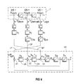
- FIG. 4 which is to be explained first for the sake of clarity, shows a control structure for precontroling rigid drive systems.
- This essentially consists of an axis control loop AR and a guide model F (both with dashed lines).
- the axis control loop AR has a position controller LR, to which an axial position target angle ⁇ w syn is applied.
- the position controller LR is followed by a speed controller DR, which can be designed as a PI element.
- While the setpoint angle ⁇ w sym is applied via a comparator V1, this is done with respect to a speed setpoint n V via a further comparator V2 connected between the output of the position controller LR and the input of the speed controller DR, to which a speed value n determined on the output side is also applied as a control value .
- the speed controller DR On the output side, the speed controller DR is followed by a further comparator V3, to which an acceleration setpoint m V is applied.
- a position angle ⁇ is generated on the output side from the values impressed in the controlled system via a substitute time constant T Ersi and two integrators T m , T ⁇ , which is fed back to V1.
- the axial setpoint angle ⁇ w sym is applied via a position setpoint path LP, the speed setpoint n V via a speed precontrol path DP and the acceleration setpoint m V via a torque precontrol path MP.
- the corresponding target values are obtained from the management model F via the pilot control paths.
- This is an acceleration setpoint on the input side supplied, from which the acceleration setpoint m V is obtained in the current regulator cycle T current via substitute time constants.
- a speed setpoint is derived from the specified acceleration setpoint in the guide model F via an integrator I2, which provides a speed precontrol value in the speed controller cycle T speed , taking into account constants k 2 and a substitute time constant T Ersi .
- Via a further integrator I1 a position setpoint is finally provided in the guide model F, from which an axial position setpoint angle ⁇ w sym is generated in the position controller cycle T position via the elements already explained in the speed precontrol path DP.
- Equations (2) and (3) can also only be implemented in the position controller cycle T position .
- a ramp-function generator implemented in the speed precontrol path for clock adaptation must then be added.
- the course of the acceleration is constant within each interpolation interval, but it can jump at the interval limits if high centrifugal forces occur (even with jerk-limited motion control and C 2 continuous path specification).
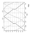
- the illustration according to FIG. 5 shows an example of a circular path which is traversed at a constant speed.
- the normalized Cartesian states of motion of the x-axis are shown if fine interpolation is carried out with degree 3 polynomials.
- the position s (t) is shown on the basis of the dotted course
- the speed s ⁇ ( t ) is shown on the basis of the dashed course
- the acceleration course is shown throughout shown. The discontinuities at the interval boundaries become clear on the basis of the course of the acceleration.
- the mechanics are subjected to hard torque surges, so that the acceleration pre-control described cannot be used.
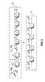
- the axis mechanism A which is the basis of an elastic two-mass system, is illustrated by means of a control path with a dashed outline.
- a torque value m is supplied on the input side, and a position angle ⁇ is present on the output side. Due to the spring-two-mass system, the speed n L on the load side is fed back to a speed n M on the drive side.
- a spring torque m F is also fed back negatively to the input of the axle mechanism A, that is to say the torque value m.
- the guide model F represents the two-store model with two integrators already described on the basis of the illustration according to FIG can be impressed into the axis control loop as in the control structure according to FIG. 4.
- the predetermined acceleration for example of a machine table of a machine tool, can now no longer be built up directly, but only with a delay in the form of the spring torque m F. In order to prevent the drives from being overloaded, this fact is suitably "corrected" in the fine interpolator according to the present invention.
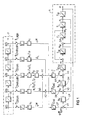
- FIG. 1 shows a control structure according to the present invention with a pilot control for elastic drive systems.
- This also contains the axis mechanism A of the elastic drive system already explained in connection with FIG. 2.
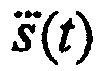
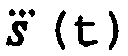
- a guide model F derived according to the representation according to FIG. 3 is shown, which consists of a chain of four successive integrators I1 to I4, on the input side with a derivative of the jerk is applied and provides a position value s (t) at the output of the last integrator I1.
- the axle mechanism A is now preceded by a controlled system for the drive system, the main components of which are a position controller LR, a subsequent speed controller DR, which can be designed as a PI element, and subsequently a replacement time constant T Ersi .
- the position angle ⁇ on the output side of the axis mechanism A is fed back negatively as a controlled variable via a comparator V1.
- the motor speed n M is fed back negatively as a controlled variable to a further comparator V2 located between the output of the position controller LR and the input of the speed controller DR.
- a third comparator V3 is arranged between the output of the speed controller DR and the input of the equivalent time constant T Ersi .
- an axial position setpoint angle axial w sym is added to the position controller LR on the input side via a position setpoint path LP.
- a speed setpoint n V is added to the output signal of the position controller LR via a speed precontrol path DP via the comparator V2.
- a drive torque setpoint m V provided via a torque precontrol path MP is added to the output signal of the speed controller DR via the third comparator V3.
- the setpoints provided via the corresponding pilot control paths LP, DP and MP are derived from the management model F.
- the nominal axial position angle ⁇ w sym is derived in the position controller cycle T position , taking into account corresponding constants such as k 1 , which corresponds to the reciprocal of the spindle pitch, and further substitute time constants T Ersi from the position value s (t) at the output of the guide model F.
- the speed controller cycle T turns the speed from the speed value available in the management model F. obtained a speed command variable n and L , which one from the jerk via an adder A2 the speed difference ⁇ n and of the management model F is added. The total value reaches the comparator V2 via an additional substitute time constant T Ersi as the axial speed setpoint n V , where it is applied to the speed controller DR.
- an axial drive torque setpoint m V is obtained from the control model F in the current controller cycle T current .
- the derivative of the jerk the size derived from a weighting via the parameter k 1 already described, which is derived from the acceleration value via a further adder A1 of the guide model F determined spring torque m and F is added.
- the axial drive torque setpoint m V is formed, weighted by the factor C -1 / 1, which is added to the output of the speed controller DR via the comparator V3.
- the required torque m explained on the basis of FIG. 3 is now already impressed into the axle mechanism A via the replacement time constant T Ersi that follows the comparator V3.
- the evaluation can be carried out using equation (10).
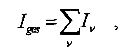
- determining the mean value of the route S can be done explicitly by first adding up the individual contributions I v of all polynomials on the total integral I tot of the path: With t ⁇ [0, T Ipo ]
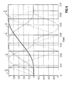
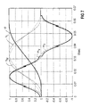
- FIGS. 6 and 7 show the application of the described method to an undamped two-mass system with a natural frequency of 92 Hz.
Landscapes
- Engineering & Computer Science (AREA)
- General Physics & Mathematics (AREA)
- Human Computer Interaction (AREA)
- Manufacturing & Machinery (AREA)
- Physics & Mathematics (AREA)
- Automation & Control Theory (AREA)
- Theoretical Computer Science (AREA)
- Computing Systems (AREA)
- Robotics (AREA)
- Mechanical Engineering (AREA)
- Feedback Control In General (AREA)
- Numerical Control (AREA)
- Springs (AREA)
Description
- 1.1
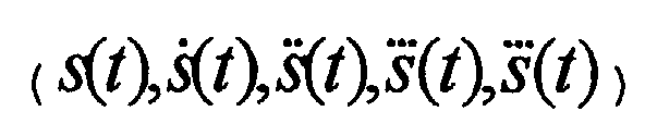
- zur Führungsgrößengenerierung werden Parameter zur Einprägung von Sollbewegungszuständen aus einem Führungsmodell mindestens vierter Ordnung zur Bewegungsführung abgeschätzt, indem daraus abgeleitet in jeden Achsregelkreis
- 1.2
- über einen Lagesollwertpfad im Interpolationstakt ein axialer Lagesollwinkel eingeprägt wird,
- 1.3
- über einen Drehzahlvorsteuerpfad im Interpolationstakt ein axialer Drehzahlsollwert eingeprägt wird und
- 1.4
- über einen Momentenvorsteuerpfad im Interpolationstakt ein axialer Antriebsmomentsollwert eingeprägt wird, wobei
- 1.5
- ein für Schwingungen ursächliches, der ausgeprägtesten Eigenfrequenz des Mehrmassensystemes zugehöriges Federmoment ebenfalls aus dem Führungsmodell abgeleitet und durch eine Störgrößenaufschaltung auf den Momentenvorsteuerpfad kompensiert wird.
- 2.1
- im Führungsmodell werden zu einer Feininterpolation Polynome vom Grad 5 oder höher verwendet.
- 3.1
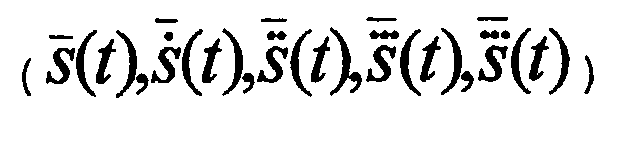
- im Rahmen einer Feininterpolation werden die einzuprägenden Sollwerte aus über ein Interpolationsintervall gemittelten Verläufen abgeleitet.
- 4.1
- die zur Mittelwertbildung der Ableitungen aus dem Weg benötigten Integrale werden direkt aus dem Führungsmodel übernommen,
- 4.2
- die Mittelwertbildung des Weges erfolgt ebenfalls explizit, indem jeweils über die Einzelbeiträge aller Polynome am Gesamtintegral des Weges aufsummiert wird und die Differenz der Summen über ein Interpolationsintervall gebildet wird.
- 5.1
- zur Führungsgrößengenerierung von Parametern zur Einprägung von Sollbewegungszuständen ist ein Führungsmodell mindestens vierter Ordnung zur Bewegungsführung vorgesehen, in welchem für jeden Achsregelkreis
- 5.2
- ein Lagesollwertpfad zum Einprägen von axialen Lagesollwinkeln im Interpolationstakt vorgesehen ist,
- 5.3
- ein Drehzahlvorsteuerpfad zum Einprägen von axialen Drehzahlsollwerten im Interpolationstakt vorgesehen ist und
- 5.4
- ein Momentenvorsteuerpfad zum Einprägen von axialen Antriebsmomentsollwerten im Interpolationstakt vorgesehen ist, wobei
- 5.5
- zur Kompensation eines für Schwingungen ursächlichen, der ausgeprägtesten Eigenfrequenz des Mehrmassensystemes zugehörigen Federmoments ein Mittel zur Störgrößenaufschaltung auf den Momentenvorsteuerpfad vorgesehen ist.
- 6.1
- es ist ein Feininterpolator vorgesehen, welcher die einzuprägenden Sollwerte aus über ein Interpolationsintervall gemittelten Eingangsgrößen interpoliert.
- FIG 1
- Regelungsstruktur mit Vorsteuerung für elastische Antriebssysteme,
- FIG 2
- Schematische Veranschaulichung der Diskrepanz zwischen Führungsmodell und Achsmechanik beim elastischen System,
- FIG 3
- Schematische Veranschaulichung des erforderlichen Moments zur Einprägung der Bewegungszustände bei elastischen Systemen,
- FIG 4
- Regelungsetruktur einer Vorsteuerung für starre Antriebssysteme,
- FIG 5
- Normierte kartesische Bewegungszustände der x-Achse beim Abfahren einer Kreisbahn,
- FIG 6
- Normierte Zustände des Führungsmodells 4. Ordnung bei einem Positioniervorgang und
- FIG 7
- Normierte Zustände der Achsmechanik bei einem Positioniervorgang entsprechend FIG 6.


- Gleichung 3 im Stromreglertakt
- Gleichung 2 im Drehzahlreglertakt
- Gleichung 1 im Lagereglertakt














Claims (6)
- Verfahren zur Momentenvorsteuerung elastischer und damit schwingungsfähiger Mehrmassensysteme wie numerisch gesteuerten Werkzeugmaschinen, Robotern oder dergleichen, mit folgenden Verfahrensschritten:
- 1.1
- zur Führungsgrößengenerierung werden Parameter zur Einprägung
von Sollbewegungszuständen aus einem Führungsmodell
mindestens vierter Ordnung zur Bewegungsführung abgeschätzt, indem daraus abgeleitet in jeden Achsregelkreis
- 1.2
- über einen Lagesollwertpfad (LP) im Interpolationstakt ein axialer Lagesollwinkel (ϕw sym) eingeprägt wird,
- 1.3
- über einen Drehzahlvorsteuerpfad (DP) im Interpolationstakt ein axialer Drehzahlsollwert (nv) eingeprägt wird und
- 1.4
- über einen Momentenvorsteuerpfad (MP) im Interpolationstakt ein axialer Antriebsmomentsollwert (mv) eingeprägt wird, wobei
- 1.5
- ein für Schwingungen ursächliches, der ausgeprägtesten
Eigenfrequenz des Mehrmassensystemes zugehöriges Federmoment
(mF) ebenfalls aus dem Führungsmodell
abgeleitet und durch eine Störgrößenaufschaltung auf den Momentenvorsteuerpfad kompensiert wird.

- Verfahren nach Anspruch 1, mit folgendem weiteren Verfahrensschritt:2.1
im Führungsmodellwerden zu einer Feininterpolation Polynome vom Grad 5 oder höher verwendet.
- Verfahren nach einem der vorangehenden Ansprüche, mit folgendem weiteren Verfahrensschritt:
- 3.1
- im Rahmen einer Feininterpolation werden die einzuprägenden
Sollwerte (ϕw sym, nv, mv) aus über ein Interpolationsintervall
gemittelten Verläufen
abgeleitet.
- Verfahren nach Anspruch 3, mit folgenden weiteren Verfahrensschritten:
- 4.1
- die zur Mittelwertbildung der Ableitungen aus dem Weg
benötigten Integrale werden direkt aus dem Führungsmodel
übernommen,

- 4.2
- die Mittelwertbildung des Weges erfolgt ebenfalls explizit, indem jeweils über die Einzelbeiträge aller Polynome am Gesamtintegral des Weges aufsummiert wird und die Differenz der Summen über ein Interpolationsintervall gebildet wird.
- Regelungsstruktur zur Momentenvorsteuerung elastischer und damit schwingungsfähiger Mehrmassensysteme wie numerisch gesteuerten Werkzeugmaschinen, Robotern oder dergleichen, mit folgenden Merkmalen:
- 5.1
- zur Führungsgrößengenerierung von Parametern zur Einprägung
von Sollbewegungszuständen ist ein Führungsmodell
mindestens vierter Ordnung zur Bewegungsführung vorgesehen, in welchem für jeden Achsregelkreis

- 5.2
- ein Lagesollwertpfad (LP) zum Einprägen von axialen Lagesollwinkeln (ϕw sym) im Interpolationstakt vorgesehen ist,
- 5.3
- ein Drehzahlvorsteuerpfad (DP) zum Einprägen von axialen Drehzahlsollwerten (nv) im Interpolationstakt vorgesehen ist und
- 5.4
- ein Momentenvorsteuerpfad (MP) zum Einprägen von axialen Antriebsmomentsollwerten (mv) im Interpolationstakt vorgesehen ist, wobei
- 5.5
- zur Kompensation eines für Schwingungen ursächlichen, der ausgeprägtesten Eigenfrequenz des Mehrmassensystemes zugehörigen Federmoments (mF) ein Mittel (A1) zur Störgrößenaufschaltung auf den Momentenvorsteuerpfad vorgesehen ist.
- Regelungsstruktur nach Anspruch 5, mit folgendem weiteren Merkmal:
- 6.1
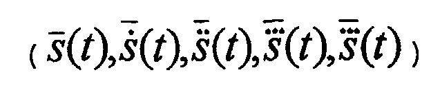
- es ist ein Feininterpolator vorgesehen, welcher die
einzuprägenden Sollwerte aus über ein Interpolationsintervall
gemittelten Eingangsgrößen
interpoliert.
Applications Claiming Priority (1)
| Application Number | Priority Date | Filing Date | Title |
|---|---|---|---|
| PCT/DE1996/001925 WO1998015880A1 (de) | 1996-10-08 | 1996-10-08 | Verfahren und regelungsstruktur zur momentenvorsteuerung numerisch geregelter, elastischer und damit schwingungsfähiger mehrmassensysteme |
Publications (2)
| Publication Number | Publication Date |
|---|---|
| EP0931283A1 EP0931283A1 (de) | 1999-07-28 |
| EP0931283B1 true EP0931283B1 (de) | 2001-03-14 |
Family
ID=6918398
Family Applications (1)
| Application Number | Title | Priority Date | Filing Date |
|---|---|---|---|
| EP96944571A Expired - Lifetime EP0931283B1 (de) | 1996-10-08 | 1996-10-08 | Verfahren und regelungsstruktur zur momentenvorsteuerung numerisch geregelter, elastischer und damit schwingungsfähiger mehrmassensysteme |
Country Status (6)
| Country | Link |
|---|---|
| US (1) | US6341244B1 (de) |
| EP (1) | EP0931283B1 (de) |
| KR (1) | KR20000048977A (de) |
| AT (1) | ATE199787T1 (de) |
| DE (1) | DE59606606D1 (de) |
| WO (1) | WO1998015880A1 (de) |
Cited By (2)
| Publication number | Priority date | Publication date | Assignee | Title |
|---|---|---|---|---|
| DE102005032336A1 (de) * | 2005-07-08 | 2007-01-11 | Fachhochschule Aschaffenburg | Verfahren zur Beeinflussung einer Steuerung oder zur Steuerung einer Bewegungseinrichtung und Steuerung oder Steuerungskomponente einer Bewegungseinrichtung |
| EP4364903A1 (de) | 2022-11-07 | 2024-05-08 | Arburg GmbH + Co KG | Verfahren zum bewegen wenigstens eines endeffektors |
Families Citing this family (13)
| Publication number | Priority date | Publication date | Assignee | Title |
|---|---|---|---|---|
| WO2001018622A1 (de) * | 1999-09-08 | 2001-03-15 | Johannes Heidenhain Gmbh | Verfahren und schaltungsanordnung zur erzeugung von lagesollwerten für einen lageregelkreis einer numerisch bahngesteuerten maschine |
| DE10104712C1 (de) * | 2001-02-02 | 2002-12-12 | Siemens Ag | Steuerungsverfahren sowie Regelungsstruktur zur Bewegungsführung, Vorsteuerung und Feininterpolation von Objekten in einem Drehzahlreglertakt, der schneller als der Lagereglertakt ist |
| US6677721B2 (en) * | 2001-02-02 | 2004-01-13 | Siemens Aktiengesellschaft | Method of control and control structure for the movement control, pre-control and fine interpolation of objects in a speed controller clock which is faster than the position controller clock |
| US7404512B2 (en) * | 2003-10-31 | 2008-07-29 | The Boeing Company | Clamping apparatus and methods for manufacturing |
| DE102004056861A1 (de) * | 2004-11-25 | 2006-06-08 | Kuka Roboter Gmbh | Verfahren und Vorrichtung zum Regeln, Steuern von Manipulatoren |
| US7112939B2 (en) * | 2004-12-07 | 2006-09-26 | Electronics And Telecommunications Research Institute | Mobile system and driving method thereof |
| US7356897B2 (en) * | 2005-05-11 | 2008-04-15 | The Boeing Company | Systems and methods for verifying a pre-programmed materials processing path |
| EP1785792A1 (de) * | 2005-11-11 | 2007-05-16 | C.C.M. Beheer B.V. | Verfahren und System zur Steuerung eines nachgiebigen Systems |
| AT507257B1 (de) * | 2008-09-10 | 2011-08-15 | Engel Austria Gmbh | Handlingteil für spritzgiessmaschine mit aktiver dämpfung |
| JP5642214B2 (ja) * | 2013-02-15 | 2014-12-17 | 株式会社神戸製鋼所 | 多関節ロボットの弾性変形補償制御装置 |
| JP5897644B2 (ja) * | 2014-06-02 | 2016-03-30 | 株式会社神戸製鋼所 | ロボットの制御装置 |
| KR102527293B1 (ko) * | 2016-11-08 | 2023-05-02 | 한국전기연구원 | 가변 임피던스 기반 공작기계 축 이동 장치 및 방법 |
| EP3653562B1 (de) * | 2018-11-19 | 2026-04-15 | ABB Schweiz AG | Verfahren und schwingungsregler zum ausregeln von schwingungen eines schwingfähigen technischen systems |
Family Cites Families (11)
| Publication number | Priority date | Publication date | Assignee | Title |
|---|---|---|---|---|
| US4734847A (en) | 1985-12-16 | 1988-03-29 | Hunter L Wayne | Microstepping motor controller circuit |
| US4761595A (en) * | 1987-05-01 | 1988-08-02 | General Motors Corporation | Motion control system having adaptive feedforward path tracking |
| US4925312A (en) * | 1988-03-21 | 1990-05-15 | Staubli International Ag | Robot control system having adaptive feedforward torque control for improved accuracy |
| US5144211A (en) * | 1989-01-31 | 1992-09-01 | Staubli International Ag | Multiaxis robot controller having workpoint torque control |
| IT1232128B (it) * | 1989-07-05 | 1992-01-23 | Advanced Data Processing | Dispositivo elettronico di interpolazione polinomiale per controlli numerici di macchine utensili, particolarmente fresatrici per la lavorazione di stampi e macchina incorporante detto dispositivo |
| JPH03118618A (ja) * | 1989-09-30 | 1991-05-21 | Fanuc Ltd | 制振効果を持つスライディングモード制御による制御方式 |
| AU1359892A (en) * | 1991-02-15 | 1992-09-15 | Incontrol, Inc. | Computer control system for generating geometric designs |
| EP0604672A1 (de) * | 1992-12-23 | 1994-07-06 | Siemens Aktiengesellschaft | Verfahren zur Drehmomentvorsteuerung von numerisch geregelten, verkoppelten Antriebssystemen |
| US5761444A (en) * | 1995-09-05 | 1998-06-02 | Intel Corporation | Method and apparatus for dynamically deferring transactions |
| US6041172A (en) * | 1997-11-26 | 2000-03-21 | Voyan Technology | Multiple scale signal processing and control system |
| US6025679A (en) * | 1998-05-06 | 2000-02-15 | Raymond G. Harper | Lighting space controller |
-
1996
- 1996-10-08 DE DE59606606T patent/DE59606606D1/de not_active Expired - Lifetime
- 1996-10-08 EP EP96944571A patent/EP0931283B1/de not_active Expired - Lifetime
- 1996-10-08 WO PCT/DE1996/001925 patent/WO1998015880A1/de not_active Ceased
- 1996-10-08 KR KR1019990703028A patent/KR20000048977A/ko not_active Withdrawn
- 1996-10-08 US US09/284,146 patent/US6341244B1/en not_active Expired - Fee Related
- 1996-10-08 AT AT96944571T patent/ATE199787T1/de active
Cited By (4)
| Publication number | Priority date | Publication date | Assignee | Title |
|---|---|---|---|---|
| DE102005032336A1 (de) * | 2005-07-08 | 2007-01-11 | Fachhochschule Aschaffenburg | Verfahren zur Beeinflussung einer Steuerung oder zur Steuerung einer Bewegungseinrichtung und Steuerung oder Steuerungskomponente einer Bewegungseinrichtung |
| DE102005032336B4 (de) * | 2005-07-08 | 2008-09-04 | Fachhochschule Aschaffenburg | Verfahren zur Beeinflussung einer Steuerung oder zur Steuerung einer Bewegungseinrichtung und Steuerung oder Steuerungskomponente einer Bewegungseinrichtung |
| EP4364903A1 (de) | 2022-11-07 | 2024-05-08 | Arburg GmbH + Co KG | Verfahren zum bewegen wenigstens eines endeffektors |
| DE102022129291A1 (de) * | 2022-11-07 | 2024-05-08 | Arburg Gmbh + Co Kg | Verfahren zum Bewegen wenigstens eines Endeffektors |
Also Published As
| Publication number | Publication date |
|---|---|
| DE59606606D1 (de) | 2001-04-19 |
| WO1998015880A1 (de) | 1998-04-16 |
| ATE199787T1 (de) | 2001-03-15 |
| US6341244B1 (en) | 2002-01-22 |
| EP0931283A1 (de) | 1999-07-28 |
| KR20000048977A (ko) | 2000-07-25 |
Similar Documents
| Publication | Publication Date | Title |
|---|---|---|
| EP2954986B1 (de) | Vorrichtung und Verfahren zum Steuern und Regeln eines Mehrkörpersystems | |
| DE102004059966B3 (de) | Verfahren und Einrichtung zur Bewegungsführung eines bewegbaren Maschinenelements einer numerisch gesteurten Maschine | |
| EP1688807B2 (de) | Verfahren zur Bewegungsaufteilung einer Relativbewegung zwischen einem Werkstück und einem Werkzeug einer Werkzeugmaschine | |
| EP1226476B1 (de) | Verfahren und schaltungsanordnung zur erzeugung von lagesollwerten für einen lageregelkreis einer numerisch bahngesteuerten maschine | |
| EP1934660B1 (de) | Verfahren und einrichtung zur bewegungsführung eines bewegbaren maschinenelements einer maschine | |
| EP0931283A1 (de) | Verfahren und regelungsstruktur zur momentenvorsteuerung numerisch geregelter, elastischer und damit schwingungsfähiger mehrmassensysteme | |
| DE3408523C2 (de) | ||
| DE102015011113A1 (de) | Motorsteuersystem, das eine Interferenz zwischen Achsen kompensiert | |
| WO2004102292A2 (de) | Verfahren zur bewegungsführung eines bewegbaren maschinenelementes einer numerisch gesteuerten werkzeug- oder produktionsmaschine | |
| EP1963935B1 (de) | Ermittlungsverfahren für eine lagegeführt abzufahrende grobbahn | |
| EP3438773B1 (de) | Bearbeitung von werkstücken mit modellgestützter fehlerkompensation | |
| DE102008050863B4 (de) | Positionssteuerungsvorrichtung | |
| EP3144754A1 (de) | Dämpfung von lastschwingungen ohne zusätzliche messmittel an der lastseite | |
| EP1977295B1 (de) | Verfahren zur achsregelung | |
| EP1226472B1 (de) | Verfahren zur ermittlung von zeitkonstanten eines referenzmodelles in einer kaskadierten regelungsanordnung | |
| EP1927906B1 (de) | Verfahren und Vorrichtung zur Lageregelung wenigstens eines Paares von Bewegungsachsen einer Maschine | |
| DE102010001829B4 (de) | Verfahren zur Bewegung eines Maschinenelements einer Maschine aus der Automatisierungstechnik und Antriebssystem | |
| DE102008019742A1 (de) | Verfahren zur Dämpfung von Maschinenresonanzen | |
| EP2016471B1 (de) | Verfahren zum koordinieren von antriebsanordnungen einer werkzeugmaschine, bahnplanungseinheit und zugehörige werkzeugmaschine | |
| EP1229411A2 (de) | Steuerungsverfahren sowie Regelungsstruktur zur Bewegungsführung, Vorsteuerung und Feininterpolation von Objekten in einem Drehzahlreglertakt, der schneller als der Lagereglertakt ist | |
| DE102009003919B4 (de) | Verfahren zur Verhinderung der Schwingungsanregung eines durch einen Antrieb bewegbaren Maschinenelements | |
| WO2001033304A2 (de) | Regelsystem für elektrische antriebe und verfahren zur bahnregelung | |
| DE102005032336B4 (de) | Verfahren zur Beeinflussung einer Steuerung oder zur Steuerung einer Bewegungseinrichtung und Steuerung oder Steuerungskomponente einer Bewegungseinrichtung | |
| DE3938083C2 (de) | ||
| DE102019125992B3 (de) | Regelung eines Robotermanipulators |
Legal Events
| Date | Code | Title | Description |
|---|---|---|---|
| PUAI | Public reference made under article 153(3) epc to a published international application that has entered the european phase |
Free format text: ORIGINAL CODE: 0009012 |
|
| 17P | Request for examination filed |
Effective date: 19990406 |
|
| AK | Designated contracting states |
Kind code of ref document: A1 Designated state(s): AT CH DE ES FR GB IT LI SE |
|
| 17Q | First examination report despatched |
Effective date: 19991015 |
|
| GRAG | Despatch of communication of intention to grant |
Free format text: ORIGINAL CODE: EPIDOS AGRA |
|
| GRAG | Despatch of communication of intention to grant |
Free format text: ORIGINAL CODE: EPIDOS AGRA |
|
| GRAH | Despatch of communication of intention to grant a patent |
Free format text: ORIGINAL CODE: EPIDOS IGRA |
|
| GRAH | Despatch of communication of intention to grant a patent |
Free format text: ORIGINAL CODE: EPIDOS IGRA |
|
| GRAA | (expected) grant |
Free format text: ORIGINAL CODE: 0009210 |
|
| AK | Designated contracting states |
Kind code of ref document: B1 Designated state(s): AT CH DE ES FR GB IT LI SE |
|
| PG25 | Lapsed in a contracting state [announced via postgrant information from national office to epo] |
Ref country code: IT Free format text: LAPSE BECAUSE OF FAILURE TO SUBMIT A TRANSLATION OF THE DESCRIPTION OR TO PAY THE FEE WITHIN THE PRESCRIBED TIME-LIMIT;WARNING: LAPSES OF ITALIAN PATENTS WITH EFFECTIVE DATE BEFORE 2007 MAY HAVE OCCURRED AT ANY TIME BEFORE 2007. THE CORRECT EFFECTIVE DATE MAY BE DIFFERENT FROM THE ONE RECORDED. Effective date: 20010314 Ref country code: GB Free format text: LAPSE BECAUSE OF FAILURE TO SUBMIT A TRANSLATION OF THE DESCRIPTION OR TO PAY THE FEE WITHIN THE PRESCRIBED TIME-LIMIT Effective date: 20010314 Ref country code: FR Free format text: LAPSE BECAUSE OF FAILURE TO SUBMIT A TRANSLATION OF THE DESCRIPTION OR TO PAY THE FEE WITHIN THE PRESCRIBED TIME-LIMIT Effective date: 20010314 |
|
| REF | Corresponds to: |
Ref document number: 199787 Country of ref document: AT Date of ref document: 20010315 Kind code of ref document: T |
|
| REG | Reference to a national code |
Ref country code: CH Ref legal event code: EP |
|
| REF | Corresponds to: |
Ref document number: 59606606 Country of ref document: DE Date of ref document: 20010419 |
|
| PG25 | Lapsed in a contracting state [announced via postgrant information from national office to epo] |
Ref country code: SE Free format text: LAPSE BECAUSE OF FAILURE TO SUBMIT A TRANSLATION OF THE DESCRIPTION OR TO PAY THE FEE WITHIN THE PRESCRIBED TIME-LIMIT Effective date: 20010614 |
|
| EN | Fr: translation not filed | ||
| GBV | Gb: ep patent (uk) treated as always having been void in accordance with gb section 77(7)/1977 [no translation filed] |
Effective date: 20010314 |
|
| PG25 | Lapsed in a contracting state [announced via postgrant information from national office to epo] |
Ref country code: ES Free format text: LAPSE BECAUSE OF FAILURE TO SUBMIT A TRANSLATION OF THE DESCRIPTION OR TO PAY THE FEE WITHIN THE PRESCRIBED TIME-LIMIT Effective date: 20010927 |
|
| PG25 | Lapsed in a contracting state [announced via postgrant information from national office to epo] |
Ref country code: AT Free format text: LAPSE BECAUSE OF NON-PAYMENT OF DUE FEES Effective date: 20011008 |
|
| PG25 | Lapsed in a contracting state [announced via postgrant information from national office to epo] |
Ref country code: LI Free format text: LAPSE BECAUSE OF NON-PAYMENT OF DUE FEES Effective date: 20011031 Ref country code: CH Free format text: LAPSE BECAUSE OF NON-PAYMENT OF DUE FEES Effective date: 20011031 |
|
| PLBE | No opposition filed within time limit |
Free format text: ORIGINAL CODE: 0009261 |
|
| STAA | Information on the status of an ep patent application or granted ep patent |
Free format text: STATUS: NO OPPOSITION FILED WITHIN TIME LIMIT |
|
| 26N | No opposition filed | ||
| REG | Reference to a national code |
Ref country code: CH Ref legal event code: PL |
|
| PGFP | Annual fee paid to national office [announced via postgrant information from national office to epo] |
Ref country code: DE Payment date: 20091218 Year of fee payment: 14 |
|
| REG | Reference to a national code |
Ref country code: DE Ref legal event code: R119 Ref document number: 59606606 Country of ref document: DE Effective date: 20110502 |
|
| PG25 | Lapsed in a contracting state [announced via postgrant information from national office to epo] |
Ref country code: DE Free format text: LAPSE BECAUSE OF NON-PAYMENT OF DUE FEES Effective date: 20110502 |