EP0931323B1 - Conducteur parallele multifilaire pour enroulements de machines et d'appareils electriques - Google Patents
Conducteur parallele multifilaire pour enroulements de machines et d'appareils electriques Download PDFInfo
- Publication number
- EP0931323B1 EP0931323B1 EP97942693A EP97942693A EP0931323B1 EP 0931323 B1 EP0931323 B1 EP 0931323B1 EP 97942693 A EP97942693 A EP 97942693A EP 97942693 A EP97942693 A EP 97942693A EP 0931323 B1 EP0931323 B1 EP 0931323B1
- Authority
- EP
- European Patent Office
- Prior art keywords
- adhesive
- conductor
- conductors
- multiple parallel
- hardening
- Prior art date
- Legal status (The legal status is an assumption and is not a legal conclusion. Google has not performed a legal analysis and makes no representation as to the accuracy of the status listed.)
- Expired - Lifetime
Links
- 239000004020 conductor Substances 0.000 title claims abstract description 59
- 238000004804 winding Methods 0.000 title claims abstract description 10
- 239000000853 adhesive Substances 0.000 claims abstract description 17
- 230000001070 adhesive effect Effects 0.000 claims abstract description 17
- 238000009413 insulation Methods 0.000 claims abstract description 9
- 239000003822 epoxy resin Substances 0.000 claims abstract description 6
- 229920000647 polyepoxide Polymers 0.000 claims abstract description 6
- 229920005989 resin Polymers 0.000 claims description 4
- 239000011347 resin Substances 0.000 claims description 4
- 238000004132 cross linking Methods 0.000 claims description 3
- 229920003002 synthetic resin Polymers 0.000 claims description 2
- 239000000057 synthetic resin Substances 0.000 claims description 2
- 239000002966 varnish Substances 0.000 claims 1
- 239000012790 adhesive layer Substances 0.000 abstract description 3
- 239000004840 adhesive resin Substances 0.000 abstract description 3
- 229920006223 adhesive resin Polymers 0.000 abstract description 3
- LNEPOXFFQSENCJ-UHFFFAOYSA-N haloperidol Chemical compound C1CC(O)(C=2C=CC(Cl)=CC=2)CCN1CCCC(=O)C1=CC=C(F)C=C1 LNEPOXFFQSENCJ-UHFFFAOYSA-N 0.000 abstract description 3
- 238000000034 method Methods 0.000 abstract description 3
- 230000000694 effects Effects 0.000 abstract 1
- 238000004519 manufacturing process Methods 0.000 description 3
- 239000003292 glue Substances 0.000 description 2
- 239000004922 lacquer Substances 0.000 description 2
- 239000010410 layer Substances 0.000 description 2
- 239000010445 mica Substances 0.000 description 2
- 229910052618 mica group Inorganic materials 0.000 description 2
- 239000003973 paint Substances 0.000 description 2
- 238000003825 pressing Methods 0.000 description 2
- 125000006850 spacer group Chemical group 0.000 description 2
- 239000011248 coating agent Substances 0.000 description 1
- 238000000576 coating method Methods 0.000 description 1
- 230000006378 damage Effects 0.000 description 1
- 230000006735 deficit Effects 0.000 description 1
- 230000002349 favourable effect Effects 0.000 description 1
- 238000010438 heat treatment Methods 0.000 description 1
- 239000000463 material Substances 0.000 description 1
- 239000002904 solvent Substances 0.000 description 1
Images


Classifications
-
- H—ELECTRICITY
- H01—ELECTRIC ELEMENTS
- H01F—MAGNETS; INDUCTANCES; TRANSFORMERS; SELECTION OF MATERIALS FOR THEIR MAGNETIC PROPERTIES
- H01F27/00—Details of transformers or inductances, in general
- H01F27/28—Coils; Windings; Conductive connections
- H01F27/2823—Wires
-
- H—ELECTRICITY
- H01—ELECTRIC ELEMENTS
- H01F—MAGNETS; INDUCTANCES; TRANSFORMERS; SELECTION OF MATERIALS FOR THEIR MAGNETIC PROPERTIES
- H01F27/00—Details of transformers or inductances, in general
- H01F27/28—Coils; Windings; Conductive connections
- H01F27/32—Insulating of coils, windings, or parts thereof
- H01F27/323—Insulation between winding turns, between winding layers
Definitions
- the invention relates to a multiple parallel conductor, i.e. a multiple conductor with parallel individual conductors, for electrical windings Machines and devices, in particular twin ladders and triple ladders, consisting of at least two individual conductors with an essentially rectangular conductor cross section, wherein each individual conductor is enamel-insulated, at least one of the longitudinal contact surfaces the flat sides of the individual conductors with a crosslinkable adhesive (2) is coated, and the conductor bundle preferably with paper insulation (3) or is surrounded by a tether.
- a multiple parallel conductor i.e. a multiple conductor with parallel individual conductors, for electrical windings Machines and devices, in particular twin ladders and triple ladders, consisting of at least two individual conductors with an essentially rectangular conductor cross section, wherein each individual conductor is enamel-insulated, at least one of the longitudinal contact surfaces the flat sides of the individual conductors with a crosslinkable adhesive (2) is coated, and the conductor bundle preferably with paper insulation (3) or is surrounded by a t
- a multiple parallel conductor of the type mentioned above is, for example, in EP 030 338 described.
- paint-insulated conductors are considered described disadvantageously and a variant is proposed at which the non-insulated individual conductors by a spacer at a distance are kept apart.
- One disadvantage of this solution is that the multiple parallel conductor is mechanically stable due to the spacer element, however occupies an undesirably higher volume. Furthermore, this results in Solution Problems related to the dielectric strength of non-oil impregnable Gas bubbles, especially around the edges.
- the individual conductors were coated with an epoxy resin after the paint insulation provided, the single conductor completely with a resin in the B state was surrounded. These individual conductors were then twisted, stranded or simply arranged in parallel, wrapped with paper insulation or tether and hardened.
- the conductors processed for example, into a transformer winding then pre-pressed, hardened and optionally re-pressed.
- the resin in the B state has escaped from the edges of the conductors, whereby gas inclusions could form.
- gas inclusions could form.
- solvent or air bubbles were trapped, it could Operation to mica and subsequently to the destruction of the insulation system come because these gas inclusions or such cavities after Heat treatment process were no longer oil-impregnable.
- the object of the invention is to provide a multiple parallel conductor whose Properties during and after winding, as well as after curing the required Meets criteria, both mechanical and electrical, and certainly not Oil-impregnable gas inclusions, especially in the narrow sides and around the edges excludes.
- the invention is based on a multiple parallel conductor of the aforementioned Kind characterized in that the edge areas and narrow sides of the individual conductors are free of adhesive.
- the adhesive is a partially cross-linked Reaction resin, preferably an epoxy resin.
- the epoxy resins have both Desired adhesive strength, as well as the required mechanical strength in the Short shot case on.
- the adhesive is an anaerobic cross-linking Synthetic resin.
- these air-hardening systems do not offer any Impairment of the desired dielectric strength, on the other hand, the Adhesive strength increased for this application, but they do not require any additional Hardening and can therefore be processed faster and cheaper.
- the adhesive is at most 95%, especially applied to 80% of the longitudinal surface. This leaves the edge and Narrow side area free of glue because the glue also on the others Manufacturing steps can no longer emerge.
- FIG. 1 shows one Twin conductor with one-sided adhesive layer
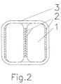
- Fig. 2 shows a twin conductor with double-sided 3 and a stranded conductor.
- the enamelled wire conductors 1 with adhesive resin 2 are on the longitudinal contact surfaces coated and wrapped with paper insulation 3.
- the bundle of ladder will be later hardened.
- the adhesive surface should be approx. 80% of the contact area and the edge and the narrow side area must remain free of adhesive.
- the enamelled wire 1 with adhesive resin 2 are both on the Longitudinal contact surfaces and coated on the outer longitudinal surfaces.
- the paper insulation 3 is wound together and thus results in a slight stronger, but more compact, twin ladder. This also applies analogously to Multiple parallel conductor consisting of three, four or more conductors.
- This wire conductor 3 is a single conductor 1 consisting of a twisted conductor with the partial one Provide coating 2.
- This wire conductor can either be with paper insulation or be provided with a tether.
- This tether may be a large-mesh network.
- the wire conductor does not necessarily have to be insulated be surrounded. The bundle of conductors remains in place due to the fastening of the individual conductors 1 practically yourself.
- the conductor bundle has one very high mechanical strength and the electrical criteria are guaranteed.
Landscapes
- Engineering & Computer Science (AREA)
- Power Engineering (AREA)
- Insulation, Fastening Of Motor, Generator Windings (AREA)
- Manufacture Of Motors, Generators (AREA)
- Insulating Of Coils (AREA)
- Insulating Bodies (AREA)
- Programmable Controllers (AREA)
- Rectifiers (AREA)
Claims (4)
- Conducteur parallèle multifilaire pour des enroulements de machines et d'appareils électriques, en particulier conducteur à bifil et conducteur trifil, constitué d'au moins deux conducteurs individuels (1) ayant une section transversale de conducteur sensiblement rectangulaire, où :caractérisé en ce quec) chaque conducteur individuel (1) est isolé par un vernis,b) au moins l'une des surfaces longitudinales de contact mutuel des côtés plats des conducteurs individuels (1) est enduite d'un adhésif (2) réticulable, etc) le faisceau de conducteur est de préférence entouré d'une isolation en papier (3) ou d'une bande de maintien,d) les zones d'arêtes et les côtés étroits des conducteurs individuels (1) sont exempts d'adhésif.
- Conducteur parallèle multifilaire selon la revendication 1, caractérisé en ce que l'adhésif (2) est appliqué sur au maximum 95 %, en particulier sur 80 % de la surface longitudinale.
- Conducteur parallèle multifilaire selon la revendication 1, caractérisé en ce que l'adhésif (2) est une résine réactive partiellement réticulée, de préférence une résine époxy.
- Conducteur parallèle multifilaire selon la revendication 1, caractérisé en ce que l'adhésif (2) est une résine synthétique réticulant de façon anaérobique.
Applications Claiming Priority (3)
| Application Number | Priority Date | Filing Date | Title |
|---|---|---|---|
| AT172796 | 1996-09-30 | ||
| AT172796 | 1996-09-30 | ||
| PCT/AT1997/000208 WO1998014964A1 (fr) | 1996-09-30 | 1997-09-24 | Conducteur parallele multifilaire pour enroulements de machines et d'appareils electriques |
Publications (2)
| Publication Number | Publication Date |
|---|---|
| EP0931323A1 EP0931323A1 (fr) | 1999-07-28 |
| EP0931323B1 true EP0931323B1 (fr) | 2000-02-02 |
Family
ID=3519713
Family Applications (1)
| Application Number | Title | Priority Date | Filing Date |
|---|---|---|---|
| EP97942693A Expired - Lifetime EP0931323B1 (fr) | 1996-09-30 | 1997-09-24 | Conducteur parallele multifilaire pour enroulements de machines et d'appareils electriques |
Country Status (4)
| Country | Link |
|---|---|
| EP (1) | EP0931323B1 (fr) |
| AT (1) | ATE189555T1 (fr) |
| DE (1) | DE59701100D1 (fr) |
| WO (1) | WO1998014964A1 (fr) |
Families Citing this family (7)
| Publication number | Priority date | Publication date | Assignee | Title |
|---|---|---|---|---|
| DE19951709A1 (de) * | 1999-10-27 | 2001-05-03 | Alcatel Sa | Elektrischer Leiter mit rechteckigem oder quadradischem Querschnitt |
| AT12993U1 (de) * | 2011-02-24 | 2013-03-15 | Asta Elektrodraht Gmbh | Kontinuierlicher Drillleiter |
| AT511154B1 (de) | 2011-02-24 | 2014-08-15 | Asta Elektrodraht Gmbh | Kontinuierlicher drillleiter |
| JP6325550B2 (ja) * | 2013-09-06 | 2018-05-16 | 古河電気工業株式会社 | 平角電線およびその製造方法並びに電気機器 |
| CN105518807B (zh) * | 2013-09-06 | 2018-05-01 | 古河电气工业株式会社 | 扁平电线及其制造方法以及电气设备 |
| JP6200480B2 (ja) * | 2015-11-20 | 2017-09-20 | 古河電気工業株式会社 | 集合電線およびその製造方法並びに電気機器 |
| RU210354U1 (ru) * | 2021-10-29 | 2022-04-11 | Акционерное общество "Москабельмет" (АО "МКМ") | Провод обмоточный подразделенный с прямоугольными медными жилами |
Family Cites Families (5)
| Publication number | Priority date | Publication date | Assignee | Title |
|---|---|---|---|---|
| CH632608A5 (en) * | 1976-09-17 | 1982-10-15 | Asea Ab | An electrical conductor which is provided with insulation which contains layers of mica between which layers consisting of a resin material are arranged |
| JPS5645008A (en) * | 1979-09-19 | 1981-04-24 | Toshiba Corp | Gas-insulated transformer |
| DE3070426D1 (en) * | 1979-12-11 | 1985-05-09 | Asea Ab | Insulated electric conductor for windings of transformers and reactive coils |
| JPS6020505A (ja) * | 1983-07-13 | 1985-02-01 | Mitsubishi Electric Corp | 紙巻線 |
| JPH04145610A (ja) * | 1990-10-08 | 1992-05-19 | Fukushima Tokai Denshi Kogyo Kk | ロータリートランスの製造方法 |
-
1997
- 1997-09-24 DE DE59701100T patent/DE59701100D1/de not_active Expired - Lifetime
- 1997-09-24 EP EP97942693A patent/EP0931323B1/fr not_active Expired - Lifetime
- 1997-09-24 AT AT97942693T patent/ATE189555T1/de active
- 1997-09-24 WO PCT/AT1997/000208 patent/WO1998014964A1/fr not_active Ceased
Also Published As
| Publication number | Publication date |
|---|---|
| ATE189555T1 (de) | 2000-02-15 |
| WO1998014964A1 (fr) | 1998-04-09 |
| DE59701100D1 (de) | 2000-03-09 |
| EP0931323A1 (fr) | 1999-07-28 |
Similar Documents
| Publication | Publication Date | Title |
|---|---|---|
| DE60107587T2 (de) | Isolationsanordnung mit abgestuftem elektrischen feld für dynamoelektrische maschine | |
| EP0368038B1 (fr) | Système d'isolation de haute tension pour machines électriques | |
| DE19817287A1 (de) | Wicklungsstab für die Hochspannungswicklung einer elektrischen Maschine sowie Verfahren zur Herstellung eines solchen Wicklungsstabes | |
| DE2506790A1 (de) | Kern- und spulen-struktur fuer dynamomaschinen und verfahren zur herstellung derselben | |
| DE3008818A1 (de) | Verbindungsmuffe fuer kuehlbares hochspannungskabel mit hohlrohrfoermiger isolierung | |
| DE3324285C2 (fr) | ||
| EP0898806B1 (fr) | Corps support pour bobinage electrique et procede de fabrication d'un dispositif anti-effluves | |
| EP0931323B1 (fr) | Conducteur parallele multifilaire pour enroulements de machines et d'appareils electriques | |
| DE69323194T2 (de) | Bandförmiger leiter für transformatoren | |
| EP1060485A1 (fr) | Conducteur multiple a ames paralleles | |
| DE2323517A1 (de) | Elektrischer kondensator | |
| CH447377A (de) | Wicklung für Spulen in elektrischen Maschinen und Geräten | |
| DE3503019C2 (de) | Elektroblech zur Herstellung von aus einer Vielzahl von Blechlagen bestehenden Eisenkernen für elektrische Geräte | |
| EP1371124B1 (fr) | Procede de production d'une barre conductrice | |
| DE2151753B2 (de) | Spule zum Einlegen In Nuten eines Stators oder Rotors einer elektrischen Maschine | |
| EP0092018B1 (fr) | Réactance, en particulier réactance isolée de l'air sans noyau magnétique | |
| DE102005055290B3 (de) | Glimmerverstärkter Isolierschlauch | |
| DE3223902C2 (de) | Verfahren zur Herstellung einer Verbindungsmuffe für Starkstromkabel und danach hergestellte Verbindungsmuffe | |
| DE2538702C2 (de) | Verfahren zur Herstellung einer Wicklungsisolation für elektrische Maschinen | |
| CH664844A5 (de) | Isoliersystem fuer lagenwicklungen. | |
| DE19951709A1 (de) | Elektrischer Leiter mit rechteckigem oder quadradischem Querschnitt | |
| EP0036911B1 (fr) | Enroulement à barre avec conducteurs partiels transposés pour une machine électrique avec tensions nominales supérieures à 3,3 kV et procédé de fabrication de l'enroulement à barre | |
| CH299052A (de) | Isoliertes elektrisches Leitergebilde und Verfahren zu dessen Herstellung. | |
| DE102019109517A1 (de) | Wicklung und Verfahren zur Herstellung einer Wicklung | |
| DE102021201993A1 (de) | Stator für eine elektrische Maschine, elektrische Maschine, Verfahren zur Herstellung eines Stators sowie Verwendung eines Isolationspapiers |
Legal Events
| Date | Code | Title | Description |
|---|---|---|---|
| PUAI | Public reference made under article 153(3) epc to a published international application that has entered the european phase |
Free format text: ORIGINAL CODE: 0009012 |
|
| GRAG | Despatch of communication of intention to grant |
Free format text: ORIGINAL CODE: EPIDOS AGRA |
|
| 17P | Request for examination filed |
Effective date: 19981125 |
|
| AK | Designated contracting states |
Kind code of ref document: A1 Designated state(s): AT CH DE FR GB IT LI NL SE |
|
| GRAG | Despatch of communication of intention to grant |
Free format text: ORIGINAL CODE: EPIDOS AGRA |
|
| GRAH | Despatch of communication of intention to grant a patent |
Free format text: ORIGINAL CODE: EPIDOS IGRA |
|
| 17Q | First examination report despatched |
Effective date: 19990726 |
|
| GRAH | Despatch of communication of intention to grant a patent |
Free format text: ORIGINAL CODE: EPIDOS IGRA |
|
| GRAA | (expected) grant |
Free format text: ORIGINAL CODE: 0009210 |
|
| AK | Designated contracting states |
Kind code of ref document: B1 Designated state(s): AT CH DE FR GB IT LI NL SE |
|
| REF | Corresponds to: |
Ref document number: 189555 Country of ref document: AT Date of ref document: 20000215 Kind code of ref document: T |
|
| REG | Reference to a national code |
Ref country code: CH Ref legal event code: EP |
|
| REF | Corresponds to: |
Ref document number: 59701100 Country of ref document: DE Date of ref document: 20000309 |
|
| ITF | It: translation for a ep patent filed | ||
| GBT | Gb: translation of ep patent filed (gb section 77(6)(a)/1977) |
Effective date: 20000321 |
|
| ET | Fr: translation filed | ||
| PLBE | No opposition filed within time limit |
Free format text: ORIGINAL CODE: 0009261 |
|
| STAA | Information on the status of an ep patent application or granted ep patent |
Free format text: STATUS: NO OPPOSITION FILED WITHIN TIME LIMIT |
|
| 26N | No opposition filed | ||
| REG | Reference to a national code |
Ref country code: GB Ref legal event code: IF02 |
|
| REG | Reference to a national code |
Ref country code: FR Ref legal event code: PLFP Year of fee payment: 20 |
|
| PGFP | Annual fee paid to national office [announced via postgrant information from national office to epo] |
Ref country code: NL Payment date: 20160920 Year of fee payment: 20 Ref country code: CH Payment date: 20160920 Year of fee payment: 20 Ref country code: GB Payment date: 20160920 Year of fee payment: 20 Ref country code: DE Payment date: 20160921 Year of fee payment: 20 |
|
| PGFP | Annual fee paid to national office [announced via postgrant information from national office to epo] |
Ref country code: FR Payment date: 20160921 Year of fee payment: 20 Ref country code: SE Payment date: 20160920 Year of fee payment: 20 Ref country code: AT Payment date: 20160929 Year of fee payment: 20 |
|
| PGFP | Annual fee paid to national office [announced via postgrant information from national office to epo] |
Ref country code: IT Payment date: 20160922 Year of fee payment: 20 |
|
| REG | Reference to a national code |
Ref country code: DE Ref legal event code: R071 Ref document number: 59701100 Country of ref document: DE |
|
| REG | Reference to a national code |
Ref country code: NL Ref legal event code: MK Effective date: 20170923 |
|
| REG | Reference to a national code |
Ref country code: CH Ref legal event code: PL |
|
| REG | Reference to a national code |
Ref country code: GB Ref legal event code: PE20 Expiry date: 20170923 |
|
| REG | Reference to a national code |
Ref country code: SE Ref legal event code: EUG |
|
| REG | Reference to a national code |
Ref country code: AT Ref legal event code: MK07 Ref document number: 189555 Country of ref document: AT Kind code of ref document: T Effective date: 20170924 |
|
| PG25 | Lapsed in a contracting state [announced via postgrant information from national office to epo] |
Ref country code: GB Free format text: LAPSE BECAUSE OF EXPIRATION OF PROTECTION Effective date: 20170923 |