EP0931375B1 - Dispositif pour le support et la mise en contact electrique de balais, en particulier pour turbogenerateurs - Google Patents
Dispositif pour le support et la mise en contact electrique de balais, en particulier pour turbogenerateurs Download PDFInfo
- Publication number
- EP0931375B1 EP0931375B1 EP97945735A EP97945735A EP0931375B1 EP 0931375 B1 EP0931375 B1 EP 0931375B1 EP 97945735 A EP97945735 A EP 97945735A EP 97945735 A EP97945735 A EP 97945735A EP 0931375 B1 EP0931375 B1 EP 0931375B1
- Authority
- EP
- European Patent Office
- Prior art keywords
- contact
- arrangement according
- shaft
- current
- supporting
- Prior art date
- Legal status (The legal status is an assumption and is not a legal conclusion. Google has not performed a legal analysis and makes no representation as to the accuracy of the status listed.)
- Expired - Lifetime
Links
- 230000035515 penetration Effects 0.000 claims 1
- 230000003019 stabilising effect Effects 0.000 claims 1
- 239000000463 material Substances 0.000 description 8
- 238000010276 construction Methods 0.000 description 5
- 239000011810 insulating material Substances 0.000 description 5
- 239000004020 conductor Substances 0.000 description 4
- 238000005516 engineering process Methods 0.000 description 3
- 229910000831 Steel Inorganic materials 0.000 description 2
- 230000005540 biological transmission Effects 0.000 description 2
- 238000004519 manufacturing process Methods 0.000 description 2
- 239000002184 metal Substances 0.000 description 2
- 239000010959 steel Substances 0.000 description 2
- 238000009423 ventilation Methods 0.000 description 2
- 238000003466 welding Methods 0.000 description 2
- 206010041953 Staring Diseases 0.000 description 1
- 230000009286 beneficial effect Effects 0.000 description 1
- 238000005260 corrosion Methods 0.000 description 1
- 230000001419 dependent effect Effects 0.000 description 1
- 230000000694 effects Effects 0.000 description 1
- 230000005611 electricity Effects 0.000 description 1
- 230000005284 excitation Effects 0.000 description 1
- 230000002349 favourable effect Effects 0.000 description 1
- 230000020169 heat generation Effects 0.000 description 1
- 238000009434 installation Methods 0.000 description 1
- 230000010355 oscillation Effects 0.000 description 1
- 239000007787 solid Substances 0.000 description 1
- 125000006850 spacer group Chemical group 0.000 description 1
- 229910001220 stainless steel Inorganic materials 0.000 description 1
- 239000010935 stainless steel Substances 0.000 description 1
Images


Classifications
-
- H—ELECTRICITY
- H02—GENERATION; CONVERSION OR DISTRIBUTION OF ELECTRIC POWER
- H02K—DYNAMO-ELECTRIC MACHINES
- H02K5/00—Casings; Enclosures; Supports
- H02K5/04—Casings or enclosures characterised by the shape, form or construction thereof
- H02K5/14—Means for supporting or protecting brushes or brush holders
- H02K5/141—Means for supporting or protecting brushes or brush holders for cooperation with slip-rings
-
- H—ELECTRICITY
- H02—GENERATION; CONVERSION OR DISTRIBUTION OF ELECTRIC POWER
- H02K—DYNAMO-ELECTRIC MACHINES
- H02K5/00—Casings; Enclosures; Supports
- H02K5/04—Casings or enclosures characterised by the shape, form or construction thereof
- H02K5/14—Means for supporting or protecting brushes or brush holders
Definitions
- the present invention relates to a device for carrying and for electrical contacting of grinding brushes with which a sliding electrical contact to slip rings can be produced on a shaft of a power generator.
- generators becomes one of stationary facilities outgoing excitation current on the slip rings of the rotor shaft transfer.
- Devices of the type mentioned are also known stationary parts for carrying grinding brushes.
- a particularly stable structure of the device on In a known embodiment is on a support base attached a plurality of bolts.
- the carrier base exists made of metal, the bolts made of an insulating material.
- the Bolts are arranged around the axis of rotation of the shaft.
- the grinding brushes themselves each held by a holder on the sleeves is attachable or removable from them.
- slip rings are used in the operation of the power generator or the electric motor on different electrical Potential.
- the sleeves for power transmission on the same slip ring are components of a power distributor.
- a power distributor still belongs to each a partially annular track with which the sleeves be short-circuited, and a power rail with Holes for attaching and connecting an electrical Connecting cable. The connections between the busbars and the partially annular busbar to the sleeves are secured by rivets or screws.
- DE 40 09 851 A1 discloses a short-circuit and brush lifting device for asynchronous motors with slip ring rotor that works largely wear-free and insensitive against pollution.
- a rotatable Actuation ring with brush actuation links are the Brushes only lifted when the slip rings are short-circuited are.
- the described device is very reliable used in continuous operation of electrical machines. she However, it is composed of up to 250 individual parts. There assembly usually only takes place at the location of the machine, is a relatively high cost for warehousing and Assembly of the components is essential.
- the US-PS 1,582,712 A relates to a 3-brush holder for electrical Machinery.
- These bolts are electric grinding brushes mechanical and electrical connectable.
- the ring becomes equidistant over its circumference surrounded by a number of magnetic elements. Two magnetic each Elements thus close a group of bolts on.
- Each group of bolts will have electrical current across them fed a line. Electric current flowing through the electrically conductive ring from a bolt group in the other bolt group flows, when it passes through the Group separating magnetic element damped because of the magnetic element caused a high impedance for this current becomes.
- FR 1 537 426 A deals with an annular plug-in brush holder for electrical machines.
- FR 1 537 425 A goes it is only about a brush holder and connecting ring.
- FR 1 537 425 A has an increased task Operational safety. This is achieved in that the electrically conductive and connecting the brushes electrical Connection performed within an insulating ring is that of two opposite, immediate adjacent ring parts. Within each An electrical conductor is guided in an annular groove. The respective contact bolts of the brushes are included connected to these electrical conductors.
- the invention has for its object a device for carrying and making electrical contact with grinding brushes to create which is easy and inexpensive to manufacture and to be assembled with high operational reliability and security.
- the Wear abrasive brushes as an electrical contact pin executed.
- a contact pin will both a load-bearing connection between at least one sanding brush and the support base, as well as an electrical contact of the grinding brush or brushes to a power distributor.
- a contact surface of the contact pin for example the edge surface of a hole in the contact pin can be.
- the contact pin advantageously has no hole, but consists of a solid electric conductive material, preferably steel, wherein the contact surface is formed by the outer surface of the bolt becomes.
- the contact pin is attached to the support base, which at least in the area of the connection points to the contact bolts is electrically insulating.
- the carrier base can, however also consist entirely of an insulating material.
- the distributor ring also acts like a contact pin two different functions: it closes the contact bolts short with each other and ensures a stable connection.
- the distributor ring can be made of the same material, in particular made of steel, how the contact bolts are made, in which case the number of materials used does not change elevated.
- all contact bolts are through the distributor ring connected to the same power distributor, which creates a particularly stable power distributor.
- the good electrical contact of a power distributor to the Sanding brushes and at least one electrical connection cable is a prerequisite for efficient functioning a power generator or an electric motor.
- a power distributor a perforated connector for fastening at least has an electrical connection line and that the Terminal and the contact surfaces of the contact bolts of the Power distributor are tinned.
- Other measures to get a good one can use low-corrosion materials, e.g. stainless steel, and / or the use of material pairings connecting line distributor ring or distributor ring grinding brush holder with the same electron work function.
- this has a support wall with a Cutout for the shaft with slip rings.
- the distributor ring contains contact bolts which have longitudinal axes, which are aligned parallel to the axis of rotation of the shaft.
- grinding brush holders of the same type as in State of the art used in one to the axis of rotation the shaft radial direction from the outside inwards a bolt can be inserted.
- the device according to the invention are all longitudinal axes of the contact bolts at approximately the same distance to the axis of rotation of the shaft. That way you can the same grinding brush holder and Abrasive brushes can be used. When changing the Sanding brushes therefore do not have to depend on the type of holder or the type of abrasive brush to be considered.
- An assembly-friendly and reliable type of attachment of contact bolts on the support base consists of a screw connection the contact pin. These each point to one End an external thread, the end of each in a threaded hole the support base is screwed. Will then at the other ends of the contact bolts, as described, a rigid distributor ring attached, then this will the screw connections secured. If the distributor ring with the contact bolt is welded, one results from Vibrations or oscillations inseparable connection also between the contact pin and the support base.
- the device has two Power distributor, which due to the insulating property of the Carrier base in the areas of the connection points to the Contact bolts are electrically isolated from each other.
- This both power distributors are on two opposite outer sides the support base or one of a plurality of base parts attached to the support base, the outer sides in approximately in the two opposite directions of the axis of rotation the wave are oriented. That way you can electrical contacts to two slip rings on different electrical potential are produced, the thereby used device parts as described by the same Carrier base or the same base part are worn.
- This one-carrier principle is already at the stand mentioned of technology realized.
- both power distributors are located on the same outside of the support base or the Base part.
- the arrangement of the two power distributors is essentially mirror-symmetrical to the carrier base or a base part, however with the exception of the attachment points of the contact bolts, which are offset from each other.
- One advantage is that for both Power distributors can use the same components. By moving the attachment points, the Carrier base are designed accordingly thinner, so that material and space can be saved.
- the power distributors and the shaft a current generator or an electric motor with a contact protection device to provide.
- a touch guard proposed that connected to the support base and which is the shaft and the power distributors on top and at the sides lying transversely to the axis of rotation of the shaft surrounds.
- Such a touch guard is already out of the State of the art known.
- a touch guard for the variant described above with two power distributors on two opposite Outside of the carrier base or a base part. It is in the direction of the axis of rotation of the shaft on both Ends open so that there is air horizontally under the touch guard can flow, with the result that on a Forced ventilation by fans or other active devices can be dispensed with.
- the contact protection hood at the top and / or on the sides horizontally across the axis of rotation of the shaft has a plurality of window-like openings, the Size is such that reaching through to the power distributor is difficult or impossible, but that is a natural one Convection movement of air due to heat generation possible on the brushes through the openings is.
- the contact protection hood with or without window-like openings, can also consist of several parts that only over the support base are interconnected.
- a contact protection hood with such window-like openings, can also under certain circumstances with devices according to the state of the art on active ventilation to be dispensed with, although the contact protection hood may be in the direction of the axis of rotation of the shaft on both Ends is closed, or only at one open end air can flow horizontally under the touch guard.
- the carrier base 1 shows a support base 1 with support feet 4 and one Base plate 11.
- the base plate 11 can, for example, on a Bottom screwed to secure and firm To ensure the status of the support base 1.
- the carrier base 1 has a semicircular rounded top wall, which has an approximately circular cutout 14 for one Has shaft with slip rings.
- the axis of rotation 22 of the The shaft is perpendicular to the two parallel outer sides the support wall and pierces the circular cutout 14 about in the middle.
- a circular section 14 instead of a circular section 14, however, differently shaped cutouts are also possible, for example to save wall material or a natural one Convection movement of air through the cutout to favor through.
- On both outer sides of the support wall there is a power distributor 17 with each four contact bolts 2, which are attached to the support wall.
- the attachment points of the two power distributors are located here 17 not against each other, but against each other transferred. Otherwise, the arrangement of the two power distributors 17 mirror-symmetrical to the support base 1.
- a distribution ring 3 is attached to each power distributor 17. On the mounting points have 3 ring bulges 13 on. Below are the distributor rings 3 as connection terminals 12 with mounting holes 16 for connection performed by electrical connection lines.
- the support wall in one piece from an insulating material.
- the carrier base 1 e.g. in Strut construction, where the struts are made of metal and wear areas of insulating material that the attachment the contact pin 2 serve.
- FIG. 2 An embodiment for the attachment of the contact pin 2, both on the carrier base 1 and on a distributor ring 3 is shown in FIG. 2.
- the carrier base 1 is made in area 5 of the connection point to the contact bolt 2 made of an insulating material. It shows a continuous Bore 6 with an internal thread into which the contact pin 2 screwed with an external thread 7 at one end is. Its other end is in a bore 8 one Distribution ring 3.
- the connection to the contact pin 2 was first through a fastening part 9, for example a screw, is secured and then welded on the face.
- the weld Accordingly, 10 lies at the end of the contact bolt.
- the Embodiment includes a substantially cylindrical Contact pin 2 with a longitudinal axis 21 and an outer Contact area 20.
- Fig. 3 shows that for the two power distributors 17 of the 1 shows the same components can be used.
- the attachment points of the Contact bolts 2 are offset from each other, but they are two distributor rings 17 constructed the same way as at the positions the fastening parts 9 and the holes 6 in the Carrier base recognizes.
- the same fact is also from the in Fig. 4 shown side view of the embodiment evident.
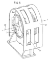
- FIG. 5 shows a second embodiment of the invention Contraption.
- a power distributor 25 is between two base parts 19 of a divided support base 18 are arranged.
- the two base parts 19 are supported by support feet 4 and are attached to the same base plate 11.
- the Power distributor 25 points in the middle between the two base parts 19 a distributor ring 3, with all contact bolts 2 is connected.
- the touch guard 23 surrounds the two power distributors 17 above and on the horizontally transverse to the axis of rotation 22 of a shaft lying sides. It is on in the direction of the axis of rotation both ends open so that there is air horizontally under the touch guard can flow.
- Constructions of a device according to the invention can, while maintaining the design principle, a Device for every possible number of abrasive brushes and arrangement of abrasive brushes to construct.
- the construction principle is thus universal for power generators and electric motors applicable to a wave.
Landscapes
- Engineering & Computer Science (AREA)
- Power Engineering (AREA)
- Motor Or Generator Current Collectors (AREA)
- Motor Or Generator Frames (AREA)
- Supercharger (AREA)
- Electrical Discharge Machining, Electrochemical Machining, And Combined Machining (AREA)
Claims (13)
- Dispositif pour le support et la mise en contact électrique de balais qui permettent de réaliser un contact électrique par frottement avec des bagues collectrices sur un arbre d'une génératrice ou d'un moteur électrique, le dispositif comprenant un support qui comporte lui-même une base (1 ; 18) de support et une pluralité de boulons fixés sur cette base, au moyen desquels au moins un balai respectif peut être assemblé à la base (1 ; 18) de support en étant supporté par cette dernière, et le dispositif comportant au moins un répartiteur (17 ; 25) de courant, qui peut être mis en contact électrique de court-circuitage avec au moins deux balais et auquel peut être raccordée au moins une ligne de raccordement électrique,
caractérisé en ce que plus d'un des boulons fait partie, en tant que boulon (2) de contact électrique pourvu d'une face (20) de contact, du ou de chaque répartiteur (17 ; 25), de sorte qu'il permet à la fois d'assembler au moins un balai en le supportant et de le mettre en contact électrique, et en ce que la base (1 ; 18) de support est électriquement isolante au moins dans les régions (5) des points d'assemblage avec les boulons (2) de contact. - Dispositif suivant la revendication 1, caractérisé en ce qu'au moins une partie, mais de préférence la totalité des boulons (2) de contact qui font partie du ou de chaque répartiteur (17 ; 25) sont mutuellement reliés avec court-circuitage et stabilisation par une bague (3) de répartition rigide.
- Dispositif suivant la revendication 1 ou 2, caractérisé en ce qu'au moins deux, mais de préférence la totalité des boulons (2) de contact du ou de chaque répartiteur (17 ; 25) sont reliés par des soudures (10) à d'autres éléments du répartiteur (17 ; 25).
- Dispositif suivant la revendication 1, 2 ou 3, caractérisé en ce que le ou chaque répartiteur (17 ; 25) comporte une borne (12) de raccordement à trous pour la fixation de la ou des lignes de raccordement électrique, et/ou les faces (20) de contact des boulons (2) de contact, en nombre supérieur à un, du répartiteur (17 ; 25) sont étamées.
- Dispositif suivant l'une des revendications 1 à 4, caractérisé en ce que la base (1 ; 18) de support comporte une paroi de support qui comprend une découpure (14) pour l'arbre pourvu des bagues collectrices.
- Dispositif suivant l'une des revendications 1 à 5, caractérisé en ce que les boulons (2) de contact possèdent des axes (21) longitudinaux qui sont orientés parallèlement à l'axe (22) de rotation de l'arbre.
- Dispositif suivant la revendication 6, caractérisé en ce que les axes longitudinaux se trouvent tous approximativement à la même distance de l'axe de rotation de l'arbre.
- Dispositif suivant l'une des revendications 1 à 7, caractérisé en ce que les boulons (2) de contact comportent un filetage (7) extérieur à une extrémité respective, et en ce que l'extrémité peut être respectivement vissée dans un trou (6) taraudé de la base (1 ; 18) de support.
- Dispositif suivant l'une des revendications 1 à 8, caractérisé en ce qu'il comprend deux répartiteurs (17) pourvus de boulons (2) de contact, qui sont isolés électriquement l'un de l'autre du fait du caractère isolant de la base (1 ; 18) de support dans les régions (5) des points d'assemblage avec les boulons (2) de contact, et en ce que les répartiteurs (17) sont fixés sur deux côtés extérieurs opposés de la base (1) de support ou d'une partie (19) de base, les côtés extérieurs étant orientés approximativement dans les deux directions opposées de l'axe de rotation de l'arbre.
- Dispositif suivant la revendication précédente, caractérisé en ce que la disposition des deux répartiteurs (17) est essentiellement symétrique par rapport à la base (1) de support ou à une partie (19) de base, à l'exception toutefois des points de fixation des boulons (2) de contact, qui sont mutuellement décalés.
- Dispositif suivant l'une des revendications 1 à 10, caractérisé en ce qu'un répartiteur (17 ; 25) pourvu de boulons (2) de contact est disposé entre deux parties (19) de base d'une base (18) de support en deux parties, les boulons (2) de contact étant fixés pour partie sur une partie (19) de base et pour partie sur l'autre partie (19) de base.
- Dispositif suivant la revendication 9 ou 10, caractérisé en ce qu'un capot (23) de protection contre les contacts accidentels est assemblé à la base (1 ; 18) de support, capot qui entoure l'arbre et les deux répartiteurs (17 ; 25) sur le dessus et sur les côtés qui sont, dans le plan horizontal, transversaux à l'axe (22) de rotation de l'arbre, et en ce que le capot (23) de protection contre les contacts accidentels est ouvert aux deux extrémités dans la direction de l'axe (22) de rotation de l'arbre, de sorte que de l'air peut s'écouler horizontalement en dessous du capot.
- Dispositif suivant la revendication précédente, caractérisé en ce que le capot (23) de protection contre les contacts accidentels comporte, sur le dessus et sur les deux côtés qui sont, dans le plan horizontal, transversaux à l'axe (22) de rotation de l'arbre, une pluralité d'ouvertures (24) du genre fenêtres, et en ce que la taille des ouvertures est calculée de telle sorte qu'il est difficile voire impossible d'atteindre le répartiteur (17 ; 25), mais qu'un déplacement d'air par convection naturelle, sur la base d'un dégagement de chaleur au niveau des balais, peut s'effectuer par ces ouvertures.
Applications Claiming Priority (3)
| Application Number | Priority Date | Filing Date | Title |
|---|---|---|---|
| DE19641834 | 1996-10-10 | ||
| DE19641834A DE19641834C2 (de) | 1996-10-10 | 1996-10-10 | Vorrichtung zum Tragen und zum elektrischen Kontaktieren von Schleifbürsten, insbesondere für Turbogeneratoren |
| PCT/DE1997/002327 WO1998015998A1 (fr) | 1996-10-10 | 1997-10-10 | Dispositif pour le support et la mise en contact electrique de balais, en particulier pour turbogenerateurs |
Publications (2)
| Publication Number | Publication Date |
|---|---|
| EP0931375A1 EP0931375A1 (fr) | 1999-07-28 |
| EP0931375B1 true EP0931375B1 (fr) | 2001-01-24 |
Family
ID=7808399
Family Applications (1)
| Application Number | Title | Priority Date | Filing Date |
|---|---|---|---|
| EP97945735A Expired - Lifetime EP0931375B1 (fr) | 1996-10-10 | 1997-10-10 | Dispositif pour le support et la mise en contact electrique de balais, en particulier pour turbogenerateurs |
Country Status (9)
| Country | Link |
|---|---|
| EP (1) | EP0931375B1 (fr) |
| JP (1) | JP3946773B2 (fr) |
| KR (1) | KR20000049008A (fr) |
| CN (1) | CN1068992C (fr) |
| AT (1) | ATE198960T1 (fr) |
| DE (2) | DE19641834C2 (fr) |
| ES (1) | ES2154476T3 (fr) |
| PL (1) | PL189981B1 (fr) |
| WO (1) | WO1998015998A1 (fr) |
Families Citing this family (4)
| Publication number | Priority date | Publication date | Assignee | Title |
|---|---|---|---|---|
| DE10203489A1 (de) * | 2002-01-30 | 2003-07-31 | Valeo Auto Electric Gmbh | Bürstentrageplatte für einen Elektromotor, Elektromotor und Verfahren zur Montage |
| DE10248977A1 (de) * | 2002-10-21 | 2004-06-03 | Siemens Ag | Anschlussstück für einen Elektromotor |
| DE112012006939B4 (de) * | 2012-09-26 | 2025-01-30 | Innomotics Gmbh | Elektrische Maschine mit verbessertem Schleifring, insbesondere für Kompressoren und Mühlen |
| EP3537577A1 (fr) * | 2018-03-08 | 2019-09-11 | Siemens Aktiengesellschaft | Unité de bague collectrice pourvue de système de refroidissement actif |
Family Cites Families (6)
| Publication number | Priority date | Publication date | Assignee | Title |
|---|---|---|---|---|
| US1582712A (en) * | 1922-07-05 | 1926-04-27 | Westinghouse Electric & Mfg Co | Current-collecting device |
| US2426815A (en) * | 1943-07-13 | 1947-09-02 | Richard A Niekamp | Brush holder |
| US3387155A (en) * | 1965-08-11 | 1968-06-04 | Gen Electric | Removable brush magazine arrangement |
| FR1537426A (fr) * | 1967-09-20 | 1968-08-23 | Bbc Brown Boveri & Cie | Collier porte-balais pour machines électriques |
| DE4009851A1 (de) * | 1990-03-23 | 1991-09-26 | Siemens Ag | Kurzschluss- und buerstenabhebevorrichtung fuer asynchronmotoren mit schleifringlaeufer |
| DE9400080U1 (de) * | 1993-01-15 | 1994-03-03 | Siemens AG, 80333 München | Trägereinrichtung für eine Bürste |
-
1996
- 1996-10-10 DE DE19641834A patent/DE19641834C2/de not_active Expired - Lifetime
-
1997
- 1997-10-10 DE DE59702959T patent/DE59702959D1/de not_active Expired - Lifetime
- 1997-10-10 WO PCT/DE1997/002327 patent/WO1998015998A1/fr not_active Ceased
- 1997-10-10 EP EP97945735A patent/EP0931375B1/fr not_active Expired - Lifetime
- 1997-10-10 KR KR1019990703068A patent/KR20000049008A/ko not_active Ceased
- 1997-10-10 CN CN97199478A patent/CN1068992C/zh not_active Expired - Lifetime
- 1997-10-10 AT AT97945735T patent/ATE198960T1/de not_active IP Right Cessation
- 1997-10-10 PL PL97332550A patent/PL189981B1/pl unknown
- 1997-10-10 JP JP51708298A patent/JP3946773B2/ja not_active Expired - Lifetime
- 1997-10-10 ES ES97945735T patent/ES2154476T3/es not_active Expired - Lifetime
Also Published As
| Publication number | Publication date |
|---|---|
| DE19641834A1 (de) | 1998-04-23 |
| WO1998015998A1 (fr) | 1998-04-16 |
| PL189981B1 (pl) | 2005-10-31 |
| JP2001501800A (ja) | 2001-02-06 |
| DE19641834C2 (de) | 1999-06-24 |
| ES2154476T3 (es) | 2001-04-01 |
| KR20000049008A (ko) | 2000-07-25 |
| ATE198960T1 (de) | 2001-02-15 |
| CN1068992C (zh) | 2001-07-25 |
| PL332550A1 (en) | 1999-09-13 |
| JP3946773B2 (ja) | 2007-07-18 |
| DE59702959D1 (de) | 2001-03-01 |
| CN1236498A (zh) | 1999-11-24 |
| EP0931375A1 (fr) | 1999-07-28 |
Similar Documents
| Publication | Publication Date | Title |
|---|---|---|
| EP2082472B1 (fr) | Moteur électrique | |
| DE69414687T2 (de) | Drehender elektrischer Schleifring mit Mehrdrahtbürsten | |
| DE69610253T2 (de) | Gleichstromgenerator, insbesondere für Kraftfahrzeug, der eine verbesserte Anordnung für Gleichrichtungsdioden enthält | |
| DE3728838C2 (fr) | ||
| EP2826114A1 (fr) | Unité de montage et procédé de montage d'un rail de montage sur une plaque de montage pour une armoire électrique | |
| DE69109569T2 (de) | Bürstenhalter für elektrische Kollektormaschine. | |
| DE102005011852A1 (de) | Verbindungsmodul für eine Verdrahtung für ein elektromechanisches Hybridgetriebe | |
| DE69011937T2 (de) | Bürstenanordnung für einen Gleichstrommotor. | |
| DE102022201399A1 (de) | Motor | |
| EP1133047B1 (fr) | Convertisseur de fréquence | |
| DE19641834C2 (de) | Vorrichtung zum Tragen und zum elektrischen Kontaktieren von Schleifbürsten, insbesondere für Turbogeneratoren | |
| EP2270821B1 (fr) | Eolienne dotée d'un onduleur et d'au moins une résistance haute tension | |
| EP1297547B1 (fr) | Barrette a connexions pour dispositifs et appareils electriques utilisables pour differents courants nominaux et comportant une cavite | |
| DE69602489T2 (de) | Mehrpoliger Gleichstrommotor | |
| DE2856762A1 (de) | Stromzufuehrungseinrichtung fuer die rotorwicklung einer elektrischen maschine | |
| DE69209617T2 (de) | Elektrischer Kleinmotor | |
| EP4713992A1 (fr) | Connecteur de module pour connexion électrique à une connexion de pôle de module d'un module de batterie, connexion de pôle de module et ensemble de connexion | |
| WO2005096478A1 (fr) | Stator long comportant une ligne de terre et train a sustentation magnetique equipe de ce stator | |
| DE20116756U1 (de) | Dreh-Durchführung zur Stromübertragung | |
| DE3932760A1 (de) | Rahmen fuer elektromotoren zum antrieb von insbesondere haushaltgeraeten | |
| EP2342799A1 (fr) | Machine électrique présentant un élément de contact pour la connexion électrique de composants électriques | |
| EP1134876A1 (fr) | Panneau d'interconnexion pour moteur électrique | |
| WO1999017430A2 (fr) | Machine electrique, notamment alternateur triphase sans bague collectrice | |
| CH683957A5 (de) | Käfigläufer mit geschlitzten Leiterstäben. | |
| EP3673173A1 (fr) | Pale de rotor d'éolienne et système paratonnerre pour une pale de rotor d'éolienne |
Legal Events
| Date | Code | Title | Description |
|---|---|---|---|
| PUAI | Public reference made under article 153(3) epc to a published international application that has entered the european phase |
Free format text: ORIGINAL CODE: 0009012 |
|
| 17P | Request for examination filed |
Effective date: 19990406 |
|
| AK | Designated contracting states |
Kind code of ref document: A1 Designated state(s): AT CH DE ES FR GB IT LI NL |
|
| GRAG | Despatch of communication of intention to grant |
Free format text: ORIGINAL CODE: EPIDOS AGRA |
|
| 17Q | First examination report despatched |
Effective date: 19991008 |
|
| GRAG | Despatch of communication of intention to grant |
Free format text: ORIGINAL CODE: EPIDOS AGRA |
|
| GRAH | Despatch of communication of intention to grant a patent |
Free format text: ORIGINAL CODE: EPIDOS IGRA |
|
| GRAH | Despatch of communication of intention to grant a patent |
Free format text: ORIGINAL CODE: EPIDOS IGRA |
|
| GRAA | (expected) grant |
Free format text: ORIGINAL CODE: 0009210 |
|
| AK | Designated contracting states |
Kind code of ref document: B1 Designated state(s): AT CH DE ES FR GB IT LI NL |
|
| REF | Corresponds to: |
Ref document number: 198960 Country of ref document: AT Date of ref document: 20010215 Kind code of ref document: T |
|
| REG | Reference to a national code |
Ref country code: CH Ref legal event code: EP |
|
| REG | Reference to a national code |
Ref country code: CH Ref legal event code: NV Representative=s name: SIEMENS SCHWEIZ AG |
|
| REF | Corresponds to: |
Ref document number: 59702959 Country of ref document: DE Date of ref document: 20010301 |
|
| GBT | Gb: translation of ep patent filed (gb section 77(6)(a)/1977) |
Effective date: 20010214 |
|
| ET | Fr: translation filed | ||
| REG | Reference to a national code |
Ref country code: ES Ref legal event code: FG2A Ref document number: 2154476 Country of ref document: ES Kind code of ref document: T3 |
|
| ITF | It: translation for a ep patent filed | ||
| PLBE | No opposition filed within time limit |
Free format text: ORIGINAL CODE: 0009261 |
|
| STAA | Information on the status of an ep patent application or granted ep patent |
Free format text: STATUS: NO OPPOSITION FILED WITHIN TIME LIMIT |
|
| REG | Reference to a national code |
Ref country code: GB Ref legal event code: IF02 |
|
| PGFP | Annual fee paid to national office [announced via postgrant information from national office to epo] |
Ref country code: CH Payment date: 20020110 Year of fee payment: 5 |
|
| 26N | No opposition filed | ||
| PGFP | Annual fee paid to national office [announced via postgrant information from national office to epo] |
Ref country code: AT Payment date: 20021004 Year of fee payment: 6 |
|
| PGFP | Annual fee paid to national office [announced via postgrant information from national office to epo] |
Ref country code: ES Payment date: 20021018 Year of fee payment: 6 |
|
| PGFP | Annual fee paid to national office [announced via postgrant information from national office to epo] |
Ref country code: NL Payment date: 20021021 Year of fee payment: 6 |
|
| PG25 | Lapsed in a contracting state [announced via postgrant information from national office to epo] |
Ref country code: LI Free format text: LAPSE BECAUSE OF NON-PAYMENT OF DUE FEES Effective date: 20021031 Ref country code: CH Free format text: LAPSE BECAUSE OF NON-PAYMENT OF DUE FEES Effective date: 20021031 |
|
| REG | Reference to a national code |
Ref country code: CH Ref legal event code: PL |
|
| PG25 | Lapsed in a contracting state [announced via postgrant information from national office to epo] |
Ref country code: AT Free format text: LAPSE BECAUSE OF NON-PAYMENT OF DUE FEES Effective date: 20031010 |
|
| PG25 | Lapsed in a contracting state [announced via postgrant information from national office to epo] |
Ref country code: ES Free format text: LAPSE BECAUSE OF NON-PAYMENT OF DUE FEES Effective date: 20031011 |
|
| PG25 | Lapsed in a contracting state [announced via postgrant information from national office to epo] |
Ref country code: NL Free format text: LAPSE BECAUSE OF NON-PAYMENT OF DUE FEES Effective date: 20040501 |
|
| NLV4 | Nl: lapsed or anulled due to non-payment of the annual fee |
Effective date: 20040501 |
|
| REG | Reference to a national code |
Ref country code: ES Ref legal event code: FD2A Effective date: 20031011 |
|
| REG | Reference to a national code |
Ref country code: FR Ref legal event code: PLFP Year of fee payment: 19 |
|
| REG | Reference to a national code |
Ref country code: FR Ref legal event code: PLFP Year of fee payment: 20 |
|
| PGFP | Annual fee paid to national office [announced via postgrant information from national office to epo] |
Ref country code: GB Payment date: 20161013 Year of fee payment: 20 Ref country code: FR Payment date: 20161028 Year of fee payment: 20 |
|
| PGFP | Annual fee paid to national office [announced via postgrant information from national office to epo] |
Ref country code: IT Payment date: 20161027 Year of fee payment: 20 |
|
| PGFP | Annual fee paid to national office [announced via postgrant information from national office to epo] |
Ref country code: DE Payment date: 20161220 Year of fee payment: 20 |
|
| REG | Reference to a national code |
Ref country code: DE Ref legal event code: R071 Ref document number: 59702959 Country of ref document: DE |
|
| REG | Reference to a national code |
Ref country code: GB Ref legal event code: PE20 Expiry date: 20171009 |
|
| PG25 | Lapsed in a contracting state [announced via postgrant information from national office to epo] |
Ref country code: GB Free format text: LAPSE BECAUSE OF EXPIRATION OF PROTECTION Effective date: 20171009 |