EP0931404B1 - Empfangssignalverarbeitungsgerät für trägerlose am-pm signale - Google Patents
Empfangssignalverarbeitungsgerät für trägerlose am-pm signale Download PDFInfo
- Publication number
- EP0931404B1 EP0931404B1 EP97909947A EP97909947A EP0931404B1 EP 0931404 B1 EP0931404 B1 EP 0931404B1 EP 97909947 A EP97909947 A EP 97909947A EP 97909947 A EP97909947 A EP 97909947A EP 0931404 B1 EP0931404 B1 EP 0931404B1
- Authority
- EP
- European Patent Office
- Prior art keywords
- signal
- cap
- cap signal
- receiver
- center frequency
- Prior art date
- Legal status (The legal status is an assumption and is not a legal conclusion. Google has not performed a legal analysis and makes no representation as to the accuracy of the status listed.)
- Expired - Lifetime
Links
- 238000012545 processing Methods 0.000 title claims description 11
- 238000000034 method Methods 0.000 claims description 22
- 238000011084 recovery Methods 0.000 claims description 6
- 230000008878 coupling Effects 0.000 claims 1
- 238000010168 coupling process Methods 0.000 claims 1
- 238000005859 coupling reaction Methods 0.000 claims 1
- 238000001914 filtration Methods 0.000 claims 1
- 230000002401 inhibitory effect Effects 0.000 claims 1
- 238000005070 sampling Methods 0.000 description 13
- 230000005540 biological transmission Effects 0.000 description 10
- 238000010586 diagram Methods 0.000 description 10
- 238000007493 shaping process Methods 0.000 description 10
- 238000010897 surface acoustic wave method Methods 0.000 description 5
- 238000006243 chemical reaction Methods 0.000 description 4
- 230000007246 mechanism Effects 0.000 description 3
- 238000012986 modification Methods 0.000 description 3
- 230000004048 modification Effects 0.000 description 3
- 238000004891 communication Methods 0.000 description 2
- 230000004044 response Effects 0.000 description 2
- 238000011161 development Methods 0.000 description 1
- 238000013507 mapping Methods 0.000 description 1
- 230000003278 mimic effect Effects 0.000 description 1
- 230000010363 phase shift Effects 0.000 description 1
- 230000008569 process Effects 0.000 description 1
- 230000000135 prohibitive effect Effects 0.000 description 1
- 238000009987 spinning Methods 0.000 description 1
- 230000003068 static effect Effects 0.000 description 1
- 230000000007 visual effect Effects 0.000 description 1
Images


Classifications
-
- H—ELECTRICITY
- H04—ELECTRIC COMMUNICATION TECHNIQUE
- H04L—TRANSMISSION OF DIGITAL INFORMATION, e.g. TELEGRAPHIC COMMUNICATION
- H04L27/00—Modulated-carrier systems
- H04L27/32—Carrier systems characterised by combinations of two or more of the types covered by groups H04L27/02, H04L27/10, H04L27/18 or H04L27/26
- H04L27/34—Amplitude- and phase-modulated carrier systems, e.g. quadrature-amplitude modulated carrier systems
- H04L27/38—Demodulator circuits; Receiver circuits
-
- H—ELECTRICITY
- H04—ELECTRIC COMMUNICATION TECHNIQUE
- H04L—TRANSMISSION OF DIGITAL INFORMATION, e.g. TELEGRAPHIC COMMUNICATION
- H04L25/00—Baseband systems
- H04L25/38—Synchronous or start-stop systems, e.g. for Baudot code
- H04L25/40—Transmitting circuits; Receiving circuits
- H04L25/49—Transmitting circuits; Receiving circuits using code conversion at the transmitter; using predistortion; using insertion of idle bits for obtaining a desired frequency spectrum; using three or more amplitude levels ; Baseband coding techniques specific to data transmission systems
- H04L25/4917—Transmitting circuits; Receiving circuits using code conversion at the transmitter; using predistortion; using insertion of idle bits for obtaining a desired frequency spectrum; using three or more amplitude levels ; Baseband coding techniques specific to data transmission systems using multilevel codes
- H04L25/4919—Transmitting circuits; Receiving circuits using code conversion at the transmitter; using predistortion; using insertion of idle bits for obtaining a desired frequency spectrum; using three or more amplitude levels ; Baseband coding techniques specific to data transmission systems using multilevel codes using balanced multilevel codes
- H04L25/4921—Transmitting circuits; Receiving circuits using code conversion at the transmitter; using predistortion; using insertion of idle bits for obtaining a desired frequency spectrum; using three or more amplitude levels ; Baseband coding techniques specific to data transmission systems using multilevel codes using balanced multilevel codes using quadrature encoding, e.g. carrierless amplitude-phase coding
Definitions
- the present invention relates to a digital signal processing system, and in particular to a receiver for processing carrierless AM/PM (CAP) signals.
- CAP carrierless AM/PM
- CAP transceivers are used to transmit and receive modulated signals over a transmission medium, such as an asymmetric digital subscriber line (ADSL) application.
- CAP is a bandwidth-efficient two-dimensional pass band line code in which the symbol data is organized in I and Q pairs.
- the I and Q data are filtered with orthogonal I and Q band pass filters having a common pass band.
- CAP is primarily intended for use in relatively simple communication links, where there is only one frequency division per channel. With CAP, all processing is done in the pass band of the filters, which eliminates the need for a carrier tracking loop (CTL), at the expense of tighter symbol timing constraints due to the frequencies of the pulses transmitted, which are higher than those of many other modulation schemes.
- CTL carrier tracking loop
- a method for processing a CAP signal to facilitate its demodulation to baseband involves the steps of processing the CAP signal by a QAM demodulator network, and removing rotation of the CAP signal about its center frequency caused by QAM demodulator processing.
- a QAM receiver is modified to receive CAP signals.
- a transmitted data symbol is represented by both "I" and "Q" quadrature components.
- Each symbol may comprise several bits, and the number of bits/symbol dictates the type of QAM (or CAP) system, i.e., 16-QAM, 32-QAM, and so forth.
- 16-QAM for example, 16 possible 4-bit symbols exist, each of which is mapped (assigned) to a prescribed coordinate in a four-quadrant grid-like constellation using a look-up table (e.g., a ROM). A prescribed number of symbols occupy assigned areas in each quadrant.
- a 32-QAM (or 32-CAP) system each quadrant of the constellation contains eight symbols at prescribed coordinates with respect to quadrature I and Q axes.
- CAP transmitter 110 comprises symbol generator 111, in-phase filter 112, quadrature filter 113, and summing node 115, which is coupled to transmission channel 120.
- CAP receiver 150 comprises in-phase filter 152, quadrature filter 153, and timing recovery mechanism 154, each coupled to transmission channel 120, sampling device 155, which is coupled to symbol to data mapper 157.
- transmission channel 120 is a standard telephone twisted pair wire.
- Symbol generator 111 receives an input data signal Data In, and maps each input data value to be transmitted to a symbol pair or pair of coordinates Ixs and Qxs of a corresponding constellation point on a complex signal constellation having real I (in-phase) and imaginary Q (quadrature) axes. Ixs and Qxs are spaced by L-1 zeros, where L is the number of samples per symbol. Filters 112 and 113 are orthogonal pulse shaping filters having a common pass band.
- the pulse shaping filter functions Pi, Pq of filters 112, 113 are derived by frequency shifting a common M tap root raised cosine filter, P, to Fc, where Fc is the center or carrier frequency of the pulse shaping filter functions Pi and Pq of filters 112 and 113.
- the input symbol data Ixs(n) and Qxs(n) are not rotated; rather, the input symbol data are only filtered by the root raised cosine orthogonal bandpass filters 112, 113.
- This generates a CAP signal which resembles, in some respects, a QAM signal, except the transmitted data is not spinning or rotating at carrier frequency Fc as it would be in a QAM system.
- the summed signal Ix(n) + Qx(n) output by summing node 115 is transmitted over transmission channel 120.
- the summed signal Ix(n) + Qx(n) is typically passed through a digital-to-analog converter (DAC) and interpolating low-pass filter (not shown) before being transmitted over transmission channel 120.
- DAC digital-to-analog converter
- summing node 115 may subtract, rather than add, the signals Ix(n) and Qx(n).
- the signal Ix(n) + Qx(n) is received by Pi and Pq filters 152, 153 of CAP receiver 150, which are related in phase and magnitude response to filters 112, 113 of CAP transmitter 110.
- CAP receiver 150 has a structure that is similar to the structure of CAP transmitter 110 in that it has a parallel arrangement of in-phase and quadrature filters. Filters 152, 153 generate signals Ix(n) and Qx(n), which are provided to sampling device 155.
- Timing recovery means 154 recovers the timing of the transmitted data, and supplies timing data to sampling device 155 to properly sample signals Ix(n) and Qx(n), to generate Ixs(n) and Qxs(n), which are used by symbol to data mapper 157 to provide the coordinates of the corresponding constellation point and thus to provide the data represented by the constellation point.
- QAM transmitter 210 comprises symbol generator 211, baseband pulse shaping filter 212, baseband pulse shaping filter 213, multipliers 216 and 217, and summing node 215, which is coupled to QAM receiver 250 via a transmission channel (not shown).
- QAM receiver 250 comprises multipliers 266, 267, baseband pulse shaping filters 252, 253, timing recovery mechanism 254, sampling device 255, complex multiplier 261, carrier tracking loop (CTL) 262, and symbol to data mapper 257.
- CTL carrier tracking loop
- QAM transmitter 210 the entire signal is modulated to frequency Fc, as opposed to frequency shifting the filters as is done with CAP system 100. Consequently, the pulse shaping filter functions P of filters 212, 213 are invoked at baseband, and the upconverted signal rotates at rate Fc.
- QAM receiver 250 the process is reversed to restore the mapped, modulated, and transmitted data.
- QAM systems are discussed in Werner, tutorial on Carrierless AM / PM, referenced above, and in Edward A. Lee & David G. Messerschmitt, Digital Communication, 2d ed. (Boston: Kluwer Academic Publishers, 1994), pages 20 et seq., 202 et seq., and 220 et seq.
- symbol generator 211 receives an input data signal Data In, and maps each input data value to be transmitted to a pair of coordinates Ixs and Qxs of a corresponding constellation point, as in the CAP system 100 of Fig. 1.
- the Ixs(n) and Qxs(n) symbols generated by symbol generator 211 are passed through baseband pulse shaping filters 212, 213, respectively, to produce band-limited I and Q values.
- These band-limited I and Q values are multiplied by a carrier and a version of that carrier shifted in phase by 90 degrees by modulators 216, 217, respectively.
- modulators 216, 217 respectively.
- the combination of these modulations causes the I and Q values to rotate in the complex plane about the carrier frequency, as will be understood by those skilled in the art.
- Modulator 216 multiplies the band limited I value by cos(2 ⁇ Fc ⁇ k ⁇ T), and modulator 217 multiplies the band limited Q value by sin(2 ⁇ Fc ⁇ k ⁇ T), where Fc is the center frequency of baseband pulse shaping filters 212, 213, k is an index variable, and 1/T is the symbol rate.
- a QAM signal can thus be seen to consist of two independently modulated carrier signals with a ⁇ /2 or 90 degree relative phase shift.
- Filters 212, 213 and filters 252, 253 are square-root raised-cosine (SQRC) filters.
- the cascade of filters 212 and 252, and of filters 213 and 253, each form a so-called "Nyquist filter," which achieves minimal inter-symbol interference according to Nyquist's theory.
- the resulting modulated signal streams are added by summing node 215 to form the QAM signal, which is thus seen to provide separate double-sideband modulation of the I and Q signals superimposed in the frequency domain.
- an upconverter (not shown) translates the low-frequency QAM signal to the transmission channel of interest, e.g. a VHF or UHF channel.
- the QAM signal is typically passed through a DAC and interpolating low-pass filter (not shown) before being transmitted over the transmission channel.
- the QAM signal is received by a tuner portion (not shown) of QAM receiver 250, which filters the selected channel and reduces the frequency of the received signal down to an intermediate frequency (IF), the output of which is applied to multipliers 266 and 267.
- the components of QAM receiver 250 generally perform inverse functions to their counterpart components in QAM transmitter 210.
- receiver 250 also contains SQRC I and Q filters 252, 253, which are "matched" to the transmit pulse shape.
- the QAM signal received by QAM receiver 250 is converted down to baseband by multiplying the received signal by multipliers 266, 267. This also causes the QAM signal to be largely derotated. Any residual rotation and phase error is removed by CTL 262.
- filters 252, 253 generate signals Ir(n) and Qr(n), which are provided to sampling device 255.
- Sampling device converts the received analog signal to digital by sampling.
- Timing recovery mechanism 254 recovers the timing of the transmitted data, and supplies timing data to sampling device 255 to enable sampling device 255 properly to sample signals Ir(n) and Qr(n), which in turn generates Irs(n) and Qrs(n).
- complex multiplier 261 receives a tracking signal from CTL 262 to remove residual rotation and constellation phase error left over after the multiplication of multipliers 266, 267.
- CTL 262 receives the data out signal and applies the tracking signal to complex multiplier 261, as will be appreciated by those skilled in the art.
- the outputs of complex multiplier 261 are applied to symbol to data mapper 257 to provide the coordinates of the corresponding constellation point and thus to provide the data represented by the constellation point.
- the received QAM signal is converted to digital by an analog-to-digital converter ADC before being applied to multipliers 266 and 267.
- sampling device 255 is replaced by an interpolator, as will be appreciated by those skilled in the art.
- QAM system 200 contains a control loop not found in CAP system 100.
- both the carrier frequency, Fc, and the symbol timing clock must be phase and frequency locked to the transmitter.
- Fc carrier frequency
- CAP CAP
- only the symbol timing information must be locked.
- the cosine and sine signals transmitted to multipliers 266, 267 of QAM receiver 250 may simply be a 1,0,-1,0 sequence, which allows the use of simple multiplexer devices to be used to perform the functions of multipliers 266, 267.
- other relationships between Fc and Fad could also be used in accordance with the requirements of a particular system.
- multipliers 266, 267 are digital multipliers or mixers of a digital demodulator comprising a numerically controlled oscillator (NCO).
- a QAM receiver to enable the QAM receiver to receive a CAP signal.
- the CAP signal may be converted up and down in the analog frequency domain.
- the digital demodulator may be modified to accept center frequencies other than Fad/4, so that the CAP signal need not be converted up and down in the analog frequency domain before being applied to the input of the modified QAM receiver. Accordingly, in one embodiment of the present invention using analog techniques, as discussed below with reference to Fig.
- a received CAP signal is shifted to being centered at Fad/4, so that the standard 1,0,-1,0 demodulator system in the QAM demodulator can bring the signal to complex baseband.
- the 1,0,-1,0 demodulation of a digital demodulator is changed to incorporate a full multiplier and NCO to allow the QAM receiver to shift the input CAP signal to baseband.
- the CTL is also modified to remove this rotation, as discussed with respect to Fig. 5.
- a block diagram of a portion 300 of a modified QAM receiver which is modified in accordance with the analog technique described above to be able to receive CAP signals transmitted by a CAP transmitter such as CAP transmitter 110 of Fig. 1.
- an Fup oscillator 302 and mixer 301 are added to the input stage of a standard QAM receiver.
- the output of mixer 301 is applied to the input of tuner stage 330, which utilizes components common to a standard QAM receiver tuner.
- Tuner stage 330 comprises a surface acoustic wave (SAW) filter 331, a gain stage 332, a multiplier 333, and Fdown oscillator 334, and low pass filter 335.
- SAW surface acoustic wave
- an input CAP signal is applied to multiplier 301, which upconverts the CAP signal up to a higher frequency.
- multiplier 301 With typical bits rates, such as DAVIC (Digital Audio Visual Integrated Circuit Council) bit rates C and D, a filter with a sharpness similar to that of a SAW filter is required to separate the upper sideband of the converted signal from the lower sideband.
- the output of multiplier 301 is applied to the input of SAW filter 331 of stage 330.
- the frequency Fup generated by oscillator 302 is selected to put the upper sideband of the upconverted signal generated by mixer 301 in the passband of SAW filter 331.
- stage 330 is applied to the remainder of a QAM receiver, which is identical to QAM receiver 250 of Fig. 2, except for a modification to the CTL derotator, discussed with reference to Fig. 5.
- the output of stage 330 is applied to the input of multipliers 266 and 267 of QAM receiver 250 of Fig. 2.
- the demodulated CAP signal is rotating about its center frequency Fc, unlike a QAM signal, which would be largely derotated at this point of QAM receiver 250.
- the CTL needs to be modified to provide an Fc derotator.
- the CTL derotator is also modified, as discussed below with respect to Fig. 5.
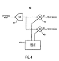
- a block diagram of a digital CAP to QAM interface portion 400 of a second modified QAM receiver which is modified in accordance with the digital technique described above to be able to receive CAP signals transmitted by a CAP transmitter such as CAP transmitter 110 of Fig. 1.
- the 1,0,-1,0 digital demodulator of a standard QAM receiver is replaced with the digital CAP to QAM interface 400 of Fig. 4, at the intermediate frequency (IF) input of the QAM receiver.
- Interface 400 incorporates a full multiplier (eg., a complex multiplier) and NCO to allow the QAM receiver to shift the input CAP signal to baseband. With appropriate gain adjustment, the CAP signal can thus be applied directly to the ADC 401, without having to be upconverted as done in QAM receiver portion 300.
- Interface 400 comprises ADC 401, coupled to inputs of multipliers or mixers 402 and 403. These multipliers replace the function of multipliers 266 and 267 of QAM receiver 250 of Fig. 2.
- the outputs of multipliers 402 and 403 are applied to filters 252 and 253, the output of which is applied to sampling device 255, which is an interpolator in this embodiment, since analog-to-digital conversion has already been performed.
- An NCO that provides center frequency Fc of the received CAP signal is also applied to inputs of multipliers 402 and 403. This replaces the simpler 1,0,-1,0 sequence that is used when the input signal has a frequency of Fad/4.
- Full multipliers 402 and 403 are also used in this embodiment, rather than simpler multipliers possible when the NCO generates the simpler 1,0,-1,0 sinusoidal sequence.
- the CTL derotator is also modified, as discussed below with respect to Fig. 5.
- Carrier tracking is an integral part of the QAM demodulation performed by a QAM receiver such as QAM receiver 250.
- a CAP system avoids this problem by not rotating data on a carrier frequency.
- the static center frequency is added to the CTL NCO, the offsets introduced by conversion tuning errors are comparable to those that exist with a QAM system and can be corrected in the standard manner.
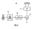
- FIG. 5 there is shown a block diagram of a modified CTL 500, which replaces CTL 262 of QAM receiver 250, in accordance with the present invention.
- This modification is necessary since the CAP symbols are rotated at Fc when they are converted to baseband by multipliers 266 and 267 (for Fig. 3) or multipliers 402 and 403 (for Fig. 4).
- the CAP signal is not rotating as a QAM signal would be.
- the QAM receiver will bring the received CAP signal down to baseband by multiplying it by a carrier which is the center frequency of the CAP signal, which causes the signal to rotate about Fc.
- the CAP symbols must have the Fc rotation removed from them.
- the center frequency can be removed only after all baseband signal processing, since adding back the center frequency to remove the rotation would shift the signal out of baseband. This requires that center frequency derotation be performed when the signal is converted to 1 sample per symbol for equalization or slicing. Accordingly, the derotation of the data must occur after pulse shaping filters 252 and 253 of a QAM receiver such as QAM receiver 250.
- derotation is performed by CTL 500.
- the modified CTL comprises a CTL phase error detector 501, which generates a CTL phase error, CTL loop filter 502, adder 510, and NCO 511.
- Phase error detector 513 generates a CTL phase error by receiving the Data Out signal, as will be appreciated.
- CTL loop filter 502 generates a signal indicating the frequency and phase error of the processed signal.
- the output of CTL loop filter 502 would be applied directly to the input of NCO 511, which would generate the correct sinusoidal signals to control the multiplication of complex multiplier 261, so as to reduce the error.
- adder 510 and signal Fc are added to allow CTL 500 to also remove the rotation caused by a CAP signal rotating about frequency Fc.
- the Fc signal can be switched to zero, so that zero is added to the error signal output by CTL loop filter 502, to mimic the operation of a normal CTL in a QAM receiver when a QAM signal is received.
- signal Fc could be provided from a switched source which provides either signal Fc or a zero value to adder 510 in response to a control signal from a sensor network which identifies the presence or absence of a CAP signal.
- a control signal from a sensor network which identifies the presence or absence of a CAP signal.
- a viewer may select a video program from a menu display. Mapping associated with the selection and with the provider of the selected source material would provide an identifier signal indicating that the selected material will be conveyed by CAP or QAM format. The identifier would be sensed eg., by a comparator, to develop the control signal.
- the modified QAM receivers and components of the present invention may be implemented partially or completely in digital signal processing software on a processor.
- An analog system may or may not need an NCO.
- a fixed NCO is suitable for generating the 1, 0, -1, 0 demodulation sequence mentioned previously.
Landscapes
- Engineering & Computer Science (AREA)
- Computer Networks & Wireless Communication (AREA)
- Signal Processing (AREA)
- Physics & Mathematics (AREA)
- Spectroscopy & Molecular Physics (AREA)
- Digital Transmission Methods That Use Modulated Carrier Waves (AREA)
Claims (20)
- Empfänger zur Verarbeitung eines CAP-Signals mit:ersten Mitteln (266, 267; 402, 403), die bewirken, dass das CAP-Signal um die Mittenfrequenz des CAP-Signal rotiert, undzweiten Mitteln (500) zur Beseitigung der Rotation des CAP- Signals um die Mittenfrequenz.
- Empfänger nach Anspruch 1, wobei die ersten Mittel einen 1,0,-1,0-Folge-Demodulator (266, 267) enthalten, wobei der Empfänger eine Analog/Digital-Abtastrate aufweist und der Empfänger ferner enthält:Mittel zur Umsetzung (330, 334) der Mittenfrequenz des CAP-Signals auf eine Frequenz, die mit der Analog/Digital-Abtastrate des Empfängers zusammenhängt, bevor das CAP-Signal dem 1,0,-1,0-Folge-Demodulator zugeführt wird.
- Empfänger nach Anspruch 2, wobei die Umsetzmittel ferner enthalten:(1) ein Bandpassfilter (252, 253), das mit dem 1,0,-1,0-Folge-Demodulator verbunden ist,(2) einen ersten Umsetzer (266) zur Umsetzung der Mittenfrequenz des CAP-Signals auf die Durchlassfrequenz, bevor das CAP-Signal dem Filter zugeführt wird, und(3) einen zweiten Umsetzer (267) zur Umsetzung der Frequenz des CAP-Signals, nachdem dieses durch das Filter auf ein Viertel der Analog/Digital-Abtastrate des Empfängers gefiltert ist.
- Empfänger nach Anspruch 1, wobei
die ersten Mittel einen Analog/Digital-Umsetzer (401) zur Umsetzung des CAP-Signals von Analog auf Digital und einen digitalen Demodulator enthalten, der eine vollständige Multiplizierstufe (402, 403) und einen numerisch gesteuerten Oszillator (NCO) (406) enthält, der zur Verschiebung des CAP-Signals in das Basisband vorgesehen ist. - Empfänger nach Anspruch 1 mit
einer Trägeranpassungsschleife (CTL) (262; 501, 502, 510, 511) für die zweiten Mittel. - Empfänger nach Anspruch 5, wobei
die CTL ein CTL-Schleifenfilter (502) mit einem Ausgang, eine Addierstufe (510) mit einem ersten und einenm zweiten Eingang, wobei der erste Eingang der Addierstufe mit dem Ausgang des CTL-Schleifenfilters verbunden ist, und einen CTL-Oszillator (511) mit einem Eingang enthält, der mit dem Ausgang der Addierstufe verbunden ist, wobei der zweite Eingang der Addierstufe mit einem Derotationssignal (fc) verbunden ist und das Derotationssignal einen von null abweichenden Wert aufweist, der ausreichend ist, dass die CTL die Rotation des CAP-Signals um die Mittenfrequenz beseitigt. - Empfänger nach Anspruch 1,
wobei die ersten Mittel Mittel (402, 403) zur Umsetzung des CAP-Signals in das Basisband enthalten. - Empfänger nach Anspruch 1, wobei
die ersten Mittel Mittel zur Multiplikation (402, 403) des CAP-Signals mit einem Trägersignal mit einer Trägerfrequenz enthalten, die gleich der Mittenfrequenz (fc) des CAP-Signals ist. - Empfänger nach Anspruch 1, wobei
die ersten Mittel Mittel zur Demodulation der QAM-Signale enthalten, wobei das CAP-Signal um die Mittenfrequenz rotiert, nachdem es durch die Mittel zur Demodulation verarbeitet worden ist. - Verfahren zum Empfang eines CAP-Signals in einem Empfänger mit folgenden Schritten:(a) Verursachung, dass das CAP-Signal um die Mittenfrequenz des CAP-Signals rotiert, und(b) Beseitigung der Rotation des CAP-Signals um die Mittenfrequenz.
- Verfahren nach Anspruch 11, wobeider Schritt (a) den Schritt der Demodulation des CAP-Signals mit einem 1,0,-1,0-Folge-Demodulator enthält, wobei der Empfänger eine Analog/Digital-Abtastrate aufweist, mit folgendem Schritt:(c) Umsetzung der Mittenfrequenz des CAP-Signals auf eine Frequenz, die mit der analog/digital-Abtastrate des Empfängers in Beziehung steht, vor der Demodulation des CAP-Signals mit dem 1,0,-1,0-Folge-Demodulator.
- Verfahren nach Anspruch 11, wobei der Schritt (c) außerdem enthält:(1) Umsetzung der Mittenfrequenz des CAP-Signals auf eine Durchlassfrequenz eines Bandpassfilters,(2) Filterung des CAP-Signals mit dem Filter nach dem Schritt (c) (1) und(3) Umsetzung der Frequenz des CAP-Signals nach dem Schritt (c)(2) auf ein Viertel der Anaiog/Digital-Abtastrate des Empfängers.
- Verfahren nach Anspruch 10, wobei
der Schritt (a) die Schritte der Umsetzung des CAP-Signals von Analog auf Digital und die Verschiebung des CAP-Signals in das Basisband mit einem digitalen Demodulator enthält, der eine vollständige Multiplizierstufe und einen NCO aufweist. - Verfahren nach Anspruch 10, wobei
der Schritt (b) durch eine CTL des Empfängers erfolgt. - Verfahren nach Anspruch 14, wobei
die CTL ein CTL-Schleifenfilter mit einem Ausgang, eine Addierstufe mit einem ersten und einem zweiten Eingang enthält, wobei der erste Eingang der Addierstufe mit dem Ausgang des CTL-Schleifenfilters verbunden ist, und einen CTL-Oszillator mit einem Eingang enthält, der mit dem Ausgang der Addierstufe verbunden ist, wobei der zweite Eingang der Addierstufe mit einem Derotationssignal verbunden ist und das Derotationssignal einen von null abweichenden Wert aufweist, der ausreicht, zu bewirken, dass die CTL die Rotation des CAP-Signals um die Mittenfrequenz beseitigt. - Verfahren nach Anspruch 10, wobei
der Schritt (a) den Schritt der Umsetzung des CAP-Signals in das Basisband enthält. - Verfahren nach Anspruch 10, wobei
der Schritt (a) den Schritt der Multiplikation des CAP-Signals mit einem Trägersignal mit einer Trägerfrequenz enthält, die gleich der Mittenfrequenz des CAP-Signals ist. - Verfahren nach Anspruch 10, wobei
der Schritt (a) den Schritt der Demodulation des CAP-Signals mit Mitteln zur Demodulation der QAM-Signale enthält, wobei das CAP-Signal nach der Demodulation um die Mittenfrequenz rotiert. - verfahren nach Anspruch 10, wobeiein CAP-Signal normalerweise keiner Rotation um eine Mittenfrequenz unterliegt undder Schritt, der die Rotation des CAP-Signals um die Mittenfrequenz des CAP-Signals bewirkt, durch Verarbeitung des CAP-Signals durch ein QAM-Demodulator-Netzwerk verursacht wird.
- Verfahren nach Anspruch 19 mit folgenden Schritten:Zuführung des CAP-Signals zu einem Trägerrückgewinnungs-Netzwerk, das zu dem QAM-Demodulatornetzwerk gehört,Erzeugung eines Referenzsignals bei der Mittenfrequenz des CAP-Signals,Zuführung des Referenzsignals zu dem Trägerrückgewinnungs-Netzwerk bei der Anwesenheit eines zu verarbeitenden CAP-Signals undSperrung des Referenzsignals bei der Abwesenheit eines zu verarbeitenden CAP-Signals.
Applications Claiming Priority (5)
| Application Number | Priority Date | Filing Date | Title |
|---|---|---|---|
| GBGB9621250.1A GB9621250D0 (en) | 1996-10-11 | 1996-10-11 | Method to receive cap via a qam receiver |
| GB9621250 | 1996-10-11 | ||
| US805198 | 1997-02-27 | ||
| US08/805,198 US5930309A (en) | 1997-02-27 | 1997-02-27 | Receiver signal processing system for cap signals |
| PCT/US1997/017829 WO1998017038A1 (en) | 1996-10-11 | 1997-10-06 | Receiver signal processing system for cap signals |
Publications (2)
| Publication Number | Publication Date |
|---|---|
| EP0931404A1 EP0931404A1 (de) | 1999-07-28 |
| EP0931404B1 true EP0931404B1 (de) | 2003-01-02 |
Family
ID=26310213
Family Applications (1)
| Application Number | Title | Priority Date | Filing Date |
|---|---|---|---|
| EP97909947A Expired - Lifetime EP0931404B1 (de) | 1996-10-11 | 1997-10-06 | Empfangssignalverarbeitungsgerät für trägerlose am-pm signale |
Country Status (7)
| Country | Link |
|---|---|
| EP (1) | EP0931404B1 (de) |
| JP (1) | JP3886160B2 (de) |
| KR (1) | KR100478130B1 (de) |
| CN (1) | CN1175641C (de) |
| AU (1) | AU4743897A (de) |
| DE (1) | DE69718190T2 (de) |
| WO (1) | WO1998017038A1 (de) |
Cited By (1)
| Publication number | Priority date | Publication date | Assignee | Title |
|---|---|---|---|---|
| US10505636B2 (en) | 2013-07-24 | 2019-12-10 | Huawei Technologies Co., Ltd. | Methods and apparatuses for sending and receiving signal, and system |
Families Citing this family (2)
| Publication number | Priority date | Publication date | Assignee | Title |
|---|---|---|---|---|
| US6252903B1 (en) * | 1998-07-02 | 2001-06-26 | Lucent Technologies Inc. | Blind start-up of a dual mode CAP-QAM receiver |
| GB2382282B (en) * | 2001-11-19 | 2003-11-12 | Lucent Technologies Inc | A digital demodulator a telecommunications receiver and a method of digital demodulation |
-
1997
- 1997-10-06 CN CNB971987262A patent/CN1175641C/zh not_active Expired - Fee Related
- 1997-10-06 EP EP97909947A patent/EP0931404B1/de not_active Expired - Lifetime
- 1997-10-06 AU AU47438/97A patent/AU4743897A/en not_active Abandoned
- 1997-10-06 JP JP51839598A patent/JP3886160B2/ja not_active Expired - Fee Related
- 1997-10-06 DE DE69718190T patent/DE69718190T2/de not_active Expired - Fee Related
- 1997-10-06 WO PCT/US1997/017829 patent/WO1998017038A1/en not_active Ceased
- 1997-10-06 KR KR10-1999-7003021A patent/KR100478130B1/ko not_active Expired - Fee Related
Cited By (1)
| Publication number | Priority date | Publication date | Assignee | Title |
|---|---|---|---|---|
| US10505636B2 (en) | 2013-07-24 | 2019-12-10 | Huawei Technologies Co., Ltd. | Methods and apparatuses for sending and receiving signal, and system |
Also Published As
| Publication number | Publication date |
|---|---|
| DE69718190T2 (de) | 2003-12-04 |
| KR100478130B1 (ko) | 2005-03-24 |
| CN1233368A (zh) | 1999-10-27 |
| CN1175641C (zh) | 2004-11-10 |
| JP3886160B2 (ja) | 2007-02-28 |
| AU4743897A (en) | 1998-05-11 |
| WO1998017038A1 (en) | 1998-04-23 |
| EP0931404A1 (de) | 1999-07-28 |
| DE69718190D1 (de) | 2003-02-06 |
| KR20000048972A (ko) | 2000-07-25 |
| JP2001504651A (ja) | 2001-04-03 |
Similar Documents
| Publication | Publication Date | Title |
|---|---|---|
| US5930309A (en) | Receiver signal processing system for cap signals | |
| JP3969745B2 (ja) | 複数ディジタル変調フォーマットを復調できる受信機 | |
| US6169767B1 (en) | Universal network interface module | |
| US6606010B1 (en) | Quadrature vestigial sideband digital communications method | |
| US5058134A (en) | Process of synchronizing a receiving modem after a training on data | |
| US6563862B1 (en) | Digital variable symbol rate modulation | |
| EP0570216B1 (de) | Prozessor zur Trägerwellenrückgewinnung für ein QAM-Fernsehsignal | |
| US5436930A (en) | Simultaneous analog and digital communications with a selection of different signal point constellations based on signal energy | |
| US5881047A (en) | Simultaneous analog and digital communication with improved phase immunity | |
| EP0697159A1 (de) | Decoder für ein auf mehrere träger moduliertes digitales fernsehsignal | |
| US6026120A (en) | System and method for using circular constellations with uncoded modulation | |
| WO1999023761A1 (en) | A field programmable radio frequency communications equipment including a configurable if circuit and method therefor | |
| JP3614762B2 (ja) | データ送信器 | |
| EP0970575B1 (de) | Netzwerk zur symboltaktrückgewinnung für ein trägenloses amplituden-phasen (cap) signal | |
| JP3517056B2 (ja) | Vsb変調信号におけるサンプリングタイミング位相誤差検出器 | |
| JP2823192B2 (ja) | 受信装置 | |
| WO1985004541A1 (en) | Single-sideband communication system | |
| JP3130716B2 (ja) | Ofdm送信装置及びofdm受信装置 | |
| EP0931404B1 (de) | Empfangssignalverarbeitungsgerät für trägerlose am-pm signale | |
| JP3614451B2 (ja) | 高精細度テレビジョン信号処理システム | |
| CN1647398B (zh) | 用于符号时钟恢复的系统和方法 | |
| Bramwell | The use of digital signal processing in satellite communication | |
| JPH03254256A (ja) | 多値数可変変復調器 | |
| Tretter | Fundamentals of Quadrature Amplitude Modulation | |
| CA2330645A1 (en) | An apparatus and method for demodulating signals |
Legal Events
| Date | Code | Title | Description |
|---|---|---|---|
| PUAI | Public reference made under article 153(3) epc to a published international application that has entered the european phase |
Free format text: ORIGINAL CODE: 0009012 |
|
| 17P | Request for examination filed |
Effective date: 19990409 |
|
| AK | Designated contracting states |
Kind code of ref document: A1 Designated state(s): DE GB IE |
|
| GRAG | Despatch of communication of intention to grant |
Free format text: ORIGINAL CODE: EPIDOS AGRA |
|
| 17Q | First examination report despatched |
Effective date: 20020529 |
|
| GRAG | Despatch of communication of intention to grant |
Free format text: ORIGINAL CODE: EPIDOS AGRA |
|
| GRAH | Despatch of communication of intention to grant a patent |
Free format text: ORIGINAL CODE: EPIDOS IGRA |
|
| GRAH | Despatch of communication of intention to grant a patent |
Free format text: ORIGINAL CODE: EPIDOS IGRA |
|
| GRAA | (expected) grant |
Free format text: ORIGINAL CODE: 0009210 |
|
| AK | Designated contracting states |
Kind code of ref document: B1 Designated state(s): DE GB IE |
|
| REG | Reference to a national code |
Ref country code: GB Ref legal event code: FG4D Free format text: 20030102 |
|
| REG | Reference to a national code |
Ref country code: IE Ref legal event code: FG4D |
|
| REF | Corresponds to: |
Ref document number: 69718190 Country of ref document: DE Date of ref document: 20030206 Kind code of ref document: P |
|
| RAP2 | Party data changed (patent owner data changed or rights of a patent transferred) |
Owner name: THOMSON MULTIMEDIA INC. |
|
| PLBE | No opposition filed within time limit |
Free format text: ORIGINAL CODE: 0009261 |
|
| STAA | Information on the status of an ep patent application or granted ep patent |
Free format text: STATUS: NO OPPOSITION FILED WITHIN TIME LIMIT |
|
| 26N | No opposition filed |
Effective date: 20031003 |
|
| PGFP | Annual fee paid to national office [announced via postgrant information from national office to epo] |
Ref country code: GB Payment date: 20070927 Year of fee payment: 11 |
|
| PGFP | Annual fee paid to national office [announced via postgrant information from national office to epo] |
Ref country code: DE Payment date: 20071022 Year of fee payment: 11 |
|
| GBPC | Gb: european patent ceased through non-payment of renewal fee |
Effective date: 20081006 |
|
| REG | Reference to a national code |
Ref country code: IE Ref legal event code: MM4A |
|
| PG25 | Lapsed in a contracting state [announced via postgrant information from national office to epo] |
Ref country code: DE Free format text: LAPSE BECAUSE OF NON-PAYMENT OF DUE FEES Effective date: 20090501 |
|
| PGFP | Annual fee paid to national office [announced via postgrant information from national office to epo] |
Ref country code: IE Payment date: 20071011 Year of fee payment: 11 |
|
| PG25 | Lapsed in a contracting state [announced via postgrant information from national office to epo] |
Ref country code: IE Free format text: LAPSE BECAUSE OF NON-PAYMENT OF DUE FEES Effective date: 20081006 |
|
| PG25 | Lapsed in a contracting state [announced via postgrant information from national office to epo] |
Ref country code: GB Free format text: LAPSE BECAUSE OF NON-PAYMENT OF DUE FEES Effective date: 20081006 |