EP0931446B1 - Dispositif de mesure dans une machine de récolte - Google Patents
Dispositif de mesure dans une machine de récolte Download PDFInfo
- Publication number
- EP0931446B1 EP0931446B1 EP98122652A EP98122652A EP0931446B1 EP 0931446 B1 EP0931446 B1 EP 0931446B1 EP 98122652 A EP98122652 A EP 98122652A EP 98122652 A EP98122652 A EP 98122652A EP 0931446 B1 EP0931446 B1 EP 0931446B1
- Authority
- EP
- European Patent Office
- Prior art keywords
- measuring apparatus
- crop
- measuring device
- crop material
- self
- Prior art date
- Legal status (The legal status is an assumption and is not a legal conclusion. Google has not performed a legal analysis and makes no representation as to the accuracy of the status listed.)
- Expired - Lifetime
Links
Images

Classifications
-
- A—HUMAN NECESSITIES
- A01—AGRICULTURE; FORESTRY; ANIMAL HUSBANDRY; HUNTING; TRAPPING; FISHING
- A01D—HARVESTING; MOWING
- A01D43/00—Mowers combined with apparatus performing additional operations while mowing
- A01D43/08—Mowers combined with apparatus performing additional operations while mowing with means for cutting up the mown crop, e.g. forage harvesters
- A01D43/085—Control or measuring arrangements specially adapted therefor
Definitions
- the invention relates to a measuring device on a mobile harvesting machine for determining a crop and / or conveyor-specific Parameters with an attachment for recording of the crop and at least one processing device for processing the crop.
- the invention relates to a measuring device on a forage harvester for harvesting silage maize, wilting grass silage or whole plant silage.
- DE 32 32 746 C2 already discloses a mobile harvesting machine with a device for Moisture measurement described by the crop by the machine.
- the moisture measurement is so important because the moisture content of the crop in the silage is crucial Has an influence on the later silage quality. If the crop / silage is too moist, it happens for example, disadvantageously to the formation of butyric acid bacteria, the silage quality affect.
- These adverse sequelae of a crop that is too moist can however, by adding / adding additives to the crop recovery largely compensated, depending on the amount of additives required of the moisture of the crop is quite different, even within one field can be.
- the measuring device built into the discharge flap has a strong abrasive effect Wear from the impacting, of which from an ejection blower up to 70 m / s strong accelerated crop is exposed, making the durability of the measuring device considerably is reduced.
- the abrasive wear is exacerbated by the fact that the crop is under Earth, small pieces of wood or stones may stick, but this cannot be ruled out can.
- the object of the invention is therefore a known measuring device for determination to attach crop and / or funding-specific parameters to a mobile harvesting machine, that this delivers reliable measurement results and also as good as possible against wear and contamination is protected.
- the measuring device in the harvester is arranged downstream of the at least one processing device and is arranged on the crop path between the processing device and the area, in which the crop flow has been brought to its final crop flow width determined for the delivery of crop.
- the influence of disturbance variables is lowest in this area.
- the orientation of the crop flow to the measuring device is always the same, so that reliable measured value acquisition without disturbing and irritating fluctuations.
- the crop flow is not or only slightly deflected by the measuring device in this area, so that a constant low pressure is exerted on the measuring device.
- the abrasive wear on the measuring device is minimal and the pressure difference is low with different crop throughputs.
- the contact pressure is low, but it is still sufficient, for example, to measure moisture using electrical conductivity. Better contacting of the crop flow to the measuring device can be improved by measuring electrodes engaging in the crop flow.
- the invention is not limited to measuring devices for moisture determination. It is general applicable for measuring devices for determining crop parameters.
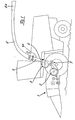
- FIG. 1 shows a forage harvester with a front attachment 1 - here a maize header, a knife drum / chopper unit 2 as a processing device, an ejection blower / ejection accelerator 3 with an ejection chute 4 and the adjoining ejection manifold 5 with an ejection flap 5A.
- the measuring device 6 is in a particularly advantageous mounting position directly after the ejection blower 3. In this area, the relatively thin crop flow is reduced from the width of the ejection blower to the width of the ejection elbow. The good flow direction is maintained by the flat discharge chute wall 4A. Between the knife drum 2 and the ejection blower 3 there is a so-called corn cracker 7, which serves for the optimal digestion of the corn kernels.
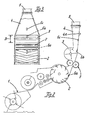
- FIG 3 is a section through the crop path in the harvester transverse to the direction of travel shown.
- the preferred possible attachment locations 6a, 6b, 6c are here again another view.
- the attachment of the measuring device 6 in the respective The center of the shaft is particularly advantageous because, with small quantities of crop, the crop flow is predominant runs in the middle of the shaft and thus already detects small crop flows can be.
- FIG. 4 shows an example of an active sensor surface of a measuring device 6 for determining moisture by means of conductivity measurement via two electrodes 9, 10.
- FIG 5 is shown schematically how the crop E according to the invention, without large To exert pressure on the measuring device 6, on the measuring device 6 parallel to the electrodes is promoted by.
- FIG. 6 shows a preferred attachment of the measuring device 6 to the wall 4A in one pivotable or removable control flap 4A '.
- This control flap 4A ' is used to control the throwing elements of the ejection blower 3 simple way in the visual checks of the discharge fan 3, also the control of the measuring device 6 enables. Furthermore, there is easy access to the measuring device 6 in the event of a repair device.
- the electrical connection lines 8 can laid easily and safely in the easily accessible space behind the chute 4 become.
Landscapes
- Life Sciences & Earth Sciences (AREA)
- Environmental Sciences (AREA)
- Investigating Or Analyzing Materials By The Use Of Electric Means (AREA)
- Testing Or Calibration Of Command Recording Devices (AREA)
- Combines (AREA)
Claims (7)
- Dispositif de mesure (6) sur une machine de récolte ou moissonneuse mobile, en particulier sur une ensileuse automotrice, pour déterminer un paramètre spécifique du produit de récolte et/ou des conditions de transport du produit de récolte, la machine de récolte comprenant un outil ou appareil frontal (1) pour prendre le produit de récolte et au moins un appareil de traitement (2) pour traiter le produit de récolte,
caractérisé par le fait qu'au moins un dispositif de mesure (6) est disposé dans la machine de récolte à la suite dudit au moins un dispositif de traitement (2) sur le trajet du produit de récolte entre l'appareil de traitement (2) et la zone dans laquelle le flux de produit de récolte (E) a été amené à sa largeur de flux de produit définitive destinée à la décharge du produit de récolte. - Dispositif de mesure (6) sur une machine de récolte automotrice suivant la revendication 1,
caractérisé par le fait que le dispositif de mesure (6) est disposé directement à la suite du dispositif de traitement (2). - Dispositif de mesure (6) sur une machine de récolte automotrice suivant au moins l'une des revendications précédentes,
caractérisé par le fait que le dispositif de mesure (6) est monté sur la paroi de la goulotte d'éjection (4). - Dispositif de mesure (6) sur une machine de récolte automotrice suivant au moins l'une des revendications précédentes,
caractérisé par le fait qu'au moins un dispositif de mesure (6) est monté sur la paroi d'un volet de contrôle (4A') pivotant ou démontable. - Dispositif de mesure (6) sur une machine de récolte automotrice suivant au moins l'une des revendications précédentes,
caractérisé par le fait que le dispositif de mesure (6) est monté au milieu (de la largeur) du flux de produit de récolte. - Dispositif de mesure (6) sur une machine de récolte automotrice suivant au moins l'une des revendications précédentes,
caractérisé par le fait que le dispositif de mesure (6) est un détecteur de mesure d'humidité. - Dispositif de mesure (6) sur une machine de récolte automotrice suivant au moins l'une des revendications précédentes,
caractérisé par le fait que le dispositif de mesure (6) est un dispositif pour déterminer le débit de produit de récolte.
Applications Claiming Priority (2)
| Application Number | Priority Date | Filing Date | Title |
|---|---|---|---|
| DE19801335 | 1998-01-16 | ||
| DE19801335 | 1998-01-16 |
Publications (2)
| Publication Number | Publication Date |
|---|---|
| EP0931446A1 EP0931446A1 (fr) | 1999-07-28 |
| EP0931446B1 true EP0931446B1 (fr) | 2003-02-12 |
Family
ID=7854719
Family Applications (1)
| Application Number | Title | Priority Date | Filing Date |
|---|---|---|---|
| EP98122652A Expired - Lifetime EP0931446B1 (fr) | 1998-01-16 | 1998-11-28 | Dispositif de mesure dans une machine de récolte |
Country Status (7)
| Country | Link |
|---|---|
| US (1) | US6257072B1 (fr) |
| EP (1) | EP0931446B1 (fr) |
| BR (1) | BR9900072A (fr) |
| DE (1) | DE59807182D1 (fr) |
| DK (1) | DK0931446T3 (fr) |
| RU (1) | RU2226328C2 (fr) |
| UA (1) | UA47482C2 (fr) |
Families Citing this family (19)
| Publication number | Priority date | Publication date | Assignee | Title |
|---|---|---|---|---|
| DE10021663A1 (de) * | 2000-05-04 | 2001-11-15 | Krone Bernhard Gmbh Maschf | Erntemaschine, insbesondere selbstfahrender Feldhäcksler |
| DE10231316A1 (de) * | 2002-07-10 | 2004-01-29 | Claas Selbstfahrende Erntemaschinen Gmbh | Verfahren und Vorrichtung zur automatischen Positionsveränderung des Nachbeschleunigungsorgans in einer landwirtschaftlichen Erntemaschine |
| DE10306725A1 (de) | 2003-02-17 | 2004-09-16 | Claas Selbstfahrende Erntemaschinen Gmbh | Verfahren und Vorrichtung zur Ermittlung von Erntegutparametern |
| DE102004038408A1 (de) * | 2004-08-07 | 2006-02-23 | Deere & Company, Moline | Messeinrichtung |
| DE102006009575A1 (de) | 2006-02-28 | 2007-09-06 | Claas Selbstfahrende Erntemaschinen Gmbh | Verfahren und Vorrichtung zur Bestimmung der Verdichtung von Erntegut |
| DE102006019243A1 (de) * | 2006-04-21 | 2007-11-08 | Claas Selbstfahrende Erntemaschinen Gmbh | Verfahren und Vorrichtung zur Einstellung der Schnittlänge einer Häckseleinrichtung einer landwirtschaftlichen Erntemaschine |
| DE102006050663A1 (de) * | 2006-09-28 | 2008-04-17 | Claas Selbstfahrende Erntemaschinen Gmbh | Messvorrichtung zur Messung von Parametern |
| RU2457657C2 (ru) * | 2007-01-24 | 2012-08-10 | КЛААС Зельбстфаренде Эрнтемашинен ГмбХ | Сельскохозяйственная рабочая машина |
| DE102007009587A1 (de) * | 2007-02-26 | 2008-08-28 | Claas Selbstfahrende Erntemaschinen Gmbh | Vorrichtung zur Einstellung der Position des Nachbeschleunigungsorgans in einer landwirtschaftlichen Erntemaschine |
| DE102007013715A1 (de) * | 2007-03-20 | 2008-09-25 | Claas Selbstfahrende Erntemaschinen Gmbh | Landwirtschaftliche Erntemaschine |
| DE102007018885A1 (de) * | 2007-04-19 | 2008-10-23 | Claas Selbstfahrende Erntemaschinen Gmbh | Landwirtschaftliche Arbeitsmaschine |
| DE102007053910A1 (de) * | 2007-11-09 | 2009-05-14 | Claas Selbstfahrende Erntemaschinen Gmbh | Landwirtschaftliche Arbeitsmaschine |
| DE102011011658A1 (de) * | 2011-02-18 | 2012-08-23 | Claas Saulgau Gmbh | Einzugsvorrichtung für einen Feldhäcksler |
| US9826683B2 (en) * | 2015-11-04 | 2017-11-28 | Deere & Company | Grain mass flow rate determination |
| RU176679U1 (ru) * | 2017-08-01 | 2018-01-25 | Федеральное государственное бюджетное образовательное учреждение высшего образования "Оренбургский государственный аграрный университет" | Установка для исследования на абразивный износ рабочих органов молотильного аппарата зерноуборочных комбайнов |
| JP7178968B2 (ja) * | 2019-06-26 | 2022-11-28 | 株式会社クボタ | 作業車 |
| US12507617B2 (en) * | 2019-06-26 | 2025-12-30 | Kubota Corporation | Work vehicle with quality determination device for grass |
| JP7118034B2 (ja) * | 2019-06-26 | 2022-08-15 | 株式会社クボタ | 作業車 |
| US20240215478A1 (en) * | 2022-12-29 | 2024-07-04 | Agco Corporation | Method for Adjusting Sensor on Swathboard of Mower |
Family Cites Families (16)
| Publication number | Priority date | Publication date | Assignee | Title |
|---|---|---|---|---|
| DE1917670C3 (de) * | 1969-04-05 | 1973-01-04 | Eimer, Manfred, Dipl.Ing., Dr., 3400 Grone | Einrichtung zur selbsttätigen Regelung des Dreschprozesses bei einem Mähdrescher |
| BE789983A (fr) * | 1971-10-12 | 1973-02-01 | Deere & Co | Dispositif de commande pour un hache-paille de champ automobile |
| DE3232746A1 (de) | 1982-09-03 | 1984-03-08 | Gerhard Dipl.-Ing. 4930 Detmold Römer | Fahrbare halmgut-erntemaschine, wie ballenpresse und ladewagen mit aufsammelvorrichtung (pickup) oder maehdrescher |
| DE3234657A1 (de) * | 1982-09-18 | 1984-03-22 | Claas Ohg, 4834 Harsewinkel | Feldhaecksler |
| EP0339141B1 (fr) * | 1988-04-26 | 1994-07-06 | New Holland Belgium N.V. | Procédé et appareil pour mesurer les pertes de grains dans des moissonneuses |
| SU1641216A1 (ru) * | 1988-06-08 | 1991-04-15 | Головное специализированное конструкторское бюро по комплексам зерноуборочных машин Государственного производственного объединения "Ростсельмаш" | Силосопровод кормоуборочного комбайна |
| DE4041995A1 (de) * | 1990-12-27 | 1992-07-02 | Mech Landwirtsch Forschzent | Verfahren und vorrichtung zur ueberwachung und regelung von funktionen eines haeckslers |
| DK0501099T3 (da) * | 1991-02-25 | 1995-04-03 | Claas Ohg | Indretning til måling af en massestrøm |
| US5173079A (en) * | 1991-02-28 | 1992-12-22 | Gerrish Steven R | Crop testing and evaluation system |
| FR2683425B1 (fr) * | 1991-11-23 | 1996-05-31 | Kloeckner Humboldt Deutz Ag | Dispositif de mesure d'un flux de grains d'une moisonneuse-batteuse. |
| US5318475A (en) * | 1992-06-19 | 1994-06-07 | Case Corporation | Apparatus for measuring mass flow of grain in a harvesting machine |
| RU2064753C1 (ru) * | 1993-08-01 | 1996-08-10 | Всероссийский научно-исследовательский и проектно-технологический институт механизации и электрификации сельского хозяйства | Кормоуборочная машина |
| DE19522441A1 (de) * | 1995-06-21 | 1997-01-02 | Same Spa | Meßvorrichtung, insbesondere für eine Körnermenge bei einem Mähdrescher |
| DE19618042A1 (de) * | 1996-05-04 | 1997-11-06 | Same Spa | Anzeige der Überkehrbelastung an Mähdreschern mit Wurfelevatoren |
| DE19641211B4 (de) | 1996-09-25 | 2005-04-14 | Claas Kgaa Mbh | Ladeeinrichtung für landwirtschaftliche Erntemaschinen |
| DE19648126B4 (de) * | 1996-11-21 | 2009-01-22 | Claas Kgaa Mbh | Selbstfahrender Feldhäcksler |
-
1998
- 1998-11-28 EP EP98122652A patent/EP0931446B1/fr not_active Expired - Lifetime
- 1998-11-28 DE DE59807182T patent/DE59807182D1/de not_active Expired - Lifetime
- 1998-11-28 DK DK98122652T patent/DK0931446T3/da active
-
1999
- 1999-01-11 RU RU99100910/12A patent/RU2226328C2/ru not_active IP Right Cessation
- 1999-01-13 UA UA99010190A patent/UA47482C2/uk unknown
- 1999-01-14 US US09/231,106 patent/US6257072B1/en not_active Expired - Fee Related
- 1999-01-15 BR BR9900072-5A patent/BR9900072A/pt not_active IP Right Cessation
Also Published As
| Publication number | Publication date |
|---|---|
| DK0931446T3 (da) | 2003-06-10 |
| UA47482C2 (uk) | 2002-07-15 |
| US6257072B1 (en) | 2001-07-10 |
| RU2226328C2 (ru) | 2004-04-10 |
| DE59807182D1 (de) | 2003-03-20 |
| EP0931446A1 (fr) | 1999-07-28 |
| BR9900072A (pt) | 2000-03-08 |
Similar Documents
| Publication | Publication Date | Title |
|---|---|---|
| EP0931446B1 (fr) | Dispositif de mesure dans une machine de récolte | |
| DE69906862T2 (de) | Verfahren zur Erzeugung von Karten des Ertrages von Pflanzen | |
| DE3232746C2 (fr) | ||
| EP2057883B1 (fr) | Machine de travail agricole | |
| EP0408850B1 (fr) | Moissonneuse automotrice | |
| EP2915422B2 (fr) | Machine agricole | |
| DE102017104009A1 (de) | Landwirtschaftliches Erntesystem | |
| DE102020132401A1 (de) | Verfahren zum Betreiben eines Mähdreschers | |
| DE3407333C2 (fr) | ||
| DE4134136C2 (fr) | ||
| EP1905292B1 (fr) | Dispositif de mesure destiné à la mesure de paramètres | |
| DE2418995C2 (fr) | ||
| EP4154699A1 (fr) | Machine de travail agricole pourvu à commande de champ caractéristique | |
| EP0404861B1 (fr) | Dispositif de traitement de cultures agricoles avec au moins un support perpendiculairement mobile au-dessus des cultures et du sol | |
| DE102015212107B4 (de) | Vorrichtung und Verfahren zur kontinuierlichen Bestimmung des Sandgehaltes von Futterpflanzen während des Ernteprozesses | |
| EP0818136A1 (fr) | Dispositif pour hacher des végétaux | |
| DE2445045A1 (de) | Maehdrescher | |
| BE1026594B1 (de) | Anordnung zur Einstellung der Position der Gegenschneide eines Feldhäckslers | |
| DE102020134033A1 (de) | Verfahren zum Sammeln einer Laborprobe | |
| DE3725712C2 (fr) | ||
| DE19820819C2 (de) | Vorrichtung und Verfahren zur Prozeßleittechnik in der Getreideernte - Verlustprüfschale | |
| DE2635846A1 (de) | Maehdrescher | |
| EP4324323A1 (fr) | Moissonneuse-batteuse automotrice dotée d'un système de capteur pour détecter la perte de grain | |
| DE2646352C2 (de) | Selbstfahrende Erntemaschine, insbesondere für Zuckerrohr | |
| EP4154700A1 (fr) | Engin d'abattage-façonnage pourvu de mécanisme de coupe de bande |
Legal Events
| Date | Code | Title | Description |
|---|---|---|---|
| PUAI | Public reference made under article 153(3) epc to a published international application that has entered the european phase |
Free format text: ORIGINAL CODE: 0009012 |
|
| AK | Designated contracting states |
Kind code of ref document: A1 Designated state(s): BE DE DK FR GB IT |
|
| AX | Request for extension of the european patent |
Free format text: AL;LT;LV;MK;RO;SI |
|
| 17P | Request for examination filed |
Effective date: 20000128 |
|
| AKX | Designation fees paid |
Free format text: BE DE DK FR GB IT |
|
| 17Q | First examination report despatched |
Effective date: 20011212 |
|
| GRAG | Despatch of communication of intention to grant |
Free format text: ORIGINAL CODE: EPIDOS AGRA |
|
| GRAG | Despatch of communication of intention to grant |
Free format text: ORIGINAL CODE: EPIDOS AGRA |
|
| GRAH | Despatch of communication of intention to grant a patent |
Free format text: ORIGINAL CODE: EPIDOS IGRA |
|
| GRAH | Despatch of communication of intention to grant a patent |
Free format text: ORIGINAL CODE: EPIDOS IGRA |
|
| GRAA | (expected) grant |
Free format text: ORIGINAL CODE: 0009210 |
|
| AK | Designated contracting states |
Designated state(s): BE DE DK FR GB IT |
|
| REG | Reference to a national code |
Ref country code: GB Ref legal event code: FG4D Free format text: NOT ENGLISH |
|
| REF | Corresponds to: |
Ref document number: 59807182 Country of ref document: DE Date of ref document: 20030320 Kind code of ref document: P |
|
| GBT | Gb: translation of ep patent filed (gb section 77(6)(a)/1977) |
Effective date: 20030329 |
|
| REG | Reference to a national code |
Ref country code: DK Ref legal event code: T3 |
|
| ET | Fr: translation filed | ||
| PLBE | No opposition filed within time limit |
Free format text: ORIGINAL CODE: 0009261 |
|
| STAA | Information on the status of an ep patent application or granted ep patent |
Free format text: STATUS: NO OPPOSITION FILED WITHIN TIME LIMIT |
|
| 26N | No opposition filed |
Effective date: 20031113 |
|
| PGFP | Annual fee paid to national office [announced via postgrant information from national office to epo] |
Ref country code: DK Payment date: 20101124 Year of fee payment: 13 |
|
| PGFP | Annual fee paid to national office [announced via postgrant information from national office to epo] |
Ref country code: GB Payment date: 20101123 Year of fee payment: 13 Ref country code: IT Payment date: 20101126 Year of fee payment: 13 |
|
| REG | Reference to a national code |
Ref country code: DK Ref legal event code: EBP |
|
| PG25 | Lapsed in a contracting state [announced via postgrant information from national office to epo] |
Ref country code: DK Free format text: LAPSE BECAUSE OF NON-PAYMENT OF DUE FEES Effective date: 20111130 |
|
| GBPC | Gb: european patent ceased through non-payment of renewal fee |
Effective date: 20121128 |
|
| PG25 | Lapsed in a contracting state [announced via postgrant information from national office to epo] |
Ref country code: IT Free format text: LAPSE BECAUSE OF NON-PAYMENT OF DUE FEES Effective date: 20121128 |
|
| PG25 | Lapsed in a contracting state [announced via postgrant information from national office to epo] |
Ref country code: GB Free format text: LAPSE BECAUSE OF NON-PAYMENT OF DUE FEES Effective date: 20121128 |
|
| REG | Reference to a national code |
Ref country code: DE Ref legal event code: R084 Ref document number: 59807182 Country of ref document: DE |
|
| REG | Reference to a national code |
Ref country code: FR Ref legal event code: PLFP Year of fee payment: 18 |
|
| PGFP | Annual fee paid to national office [announced via postgrant information from national office to epo] |
Ref country code: BE Payment date: 20151124 Year of fee payment: 18 Ref country code: FR Payment date: 20151124 Year of fee payment: 18 |
|
| PGFP | Annual fee paid to national office [announced via postgrant information from national office to epo] |
Ref country code: DE Payment date: 20161026 Year of fee payment: 19 |
|
| PG25 | Lapsed in a contracting state [announced via postgrant information from national office to epo] |
Ref country code: BE Free format text: LAPSE BECAUSE OF NON-PAYMENT OF DUE FEES Effective date: 20161130 |
|
| REG | Reference to a national code |
Ref country code: FR Ref legal event code: ST Effective date: 20170731 |
|
| PG25 | Lapsed in a contracting state [announced via postgrant information from national office to epo] |
Ref country code: FR Free format text: LAPSE BECAUSE OF NON-PAYMENT OF DUE FEES Effective date: 20161130 |
|
| REG | Reference to a national code |
Ref country code: BE Ref legal event code: MM Effective date: 20161130 |
|
| REG | Reference to a national code |
Ref country code: DE Ref legal event code: R119 Ref document number: 59807182 Country of ref document: DE |
|
| PG25 | Lapsed in a contracting state [announced via postgrant information from national office to epo] |
Ref country code: DE Free format text: LAPSE BECAUSE OF NON-PAYMENT OF DUE FEES Effective date: 20180602 |