EP0931447A1 - Conditionneur de récolte - Google Patents
Conditionneur de récolte Download PDFInfo
- Publication number
- EP0931447A1 EP0931447A1 EP99300338A EP99300338A EP0931447A1 EP 0931447 A1 EP0931447 A1 EP 0931447A1 EP 99300338 A EP99300338 A EP 99300338A EP 99300338 A EP99300338 A EP 99300338A EP 0931447 A1 EP0931447 A1 EP 0931447A1
- Authority
- EP
- European Patent Office
- Prior art keywords
- crop
- conditioning device
- conditioning
- agricultural machine
- machine according
- Prior art date
- Legal status (The legal status is an assumption and is not a legal conclusion. Google has not performed a legal analysis and makes no representation as to the accuracy of the status listed.)
- Withdrawn
Links
- 230000003750 conditioning effect Effects 0.000 claims abstract description 82
- 230000001143 conditioned effect Effects 0.000 claims abstract description 14
- 230000003245 working effect Effects 0.000 claims abstract description 8
- 238000007599 discharging Methods 0.000 claims abstract description 5
- 244000025254 Cannabis sativa Species 0.000 claims description 27
- 238000001035 drying Methods 0.000 description 10
- 239000004460 silage Substances 0.000 description 5
- 239000000463 material Substances 0.000 description 4
- 230000015572 biosynthetic process Effects 0.000 description 3
- 238000000926 separation method Methods 0.000 description 3
- 241001494496 Leersia Species 0.000 description 2
- 239000010410 layer Substances 0.000 description 2
- 208000034656 Contusions Diseases 0.000 description 1
- 240000004658 Medicago sativa Species 0.000 description 1
- 235000010624 Medicago sativa Nutrition 0.000 description 1
- 241000219793 Trifolium Species 0.000 description 1
- 230000002411 adverse Effects 0.000 description 1
- 208000034526 bruise Diseases 0.000 description 1
- 230000000694 effects Effects 0.000 description 1
- 239000004459 forage Substances 0.000 description 1
- 230000001771 impaired effect Effects 0.000 description 1
- 230000010354 integration Effects 0.000 description 1
- 230000001737 promoting effect Effects 0.000 description 1
- 239000002344 surface layer Substances 0.000 description 1
- 238000011144 upstream manufacturing Methods 0.000 description 1
- 238000009736 wetting Methods 0.000 description 1
Images

Classifications
-
- A—HUMAN NECESSITIES
- A01—AGRICULTURE; FORESTRY; ANIMAL HUSBANDRY; HUNTING; TRAPPING; FISHING
- A01D—HARVESTING; MOWING
- A01D43/00—Mowers combined with apparatus performing additional operations while mowing
- A01D43/10—Mowers combined with apparatus performing additional operations while mowing with means for crushing or bruising the mown crop
Definitions
- This invention relates to an agricultural machine for conditioning a mown crop, and which includes a rotatable conditioning device which is operative to apply a mechanical working action to the outer surface of the crop to improve the conditioning of the crop.
- the invention has been developed primarily in connection with the conditioning of mown grass, so as to speed-up the drying process and thereby allow subsequent crop handling equipment to be used sooner. Furthermore, it is desirable to reduce the length of the necessary drying time in which the conditioned crop is lying on the ground and is losing moisture content, until the grass reaches required proportion of dry matter content.
- the dry matter content has to be controlled within set limits, and the longer the length of the drying time, the greater the chance of the quality of the silage being impaired by adverse weather conditions e.g. sudden showers of rain falling on partly dried and conditioned crop lying on the ground.
- the conditioning equipment consists of a rotatable brush having relatively soft bristles, but in another example the conditioning component comprises a rotor on which are mounted relatively stiff or rigid radially projecting crop engaging elements or tines.
- the co-operating holding component can be designed either as a stationary element having stiff projecting elements which extend towards the conditioning component, or alternatively the holding component can take the form of a rotating unit rotating with, or against the conditioning component.
- Crop conditioners can be supplied as a piece of separate equipment to a mower, so that two separate operations must take place i.e. first the standing crop of grass must be cut and then deposited in swaths on the ground by the mower, and subsequently the crop conditioner is used to pick-up the swaths, to "condition" the grass, and then return the grass to the field for further drying.
- a crop conditioner can be integrated with a mower to form a single piece of equipment, which is able to cut a standing crop, apply a conditioning action to the cut crop, and then deposit the conditioned crop in swaths on the field for required drying. After required drying has been completed, the swaths can then be picked-up by a baler, or a forage storage wagon.
- disc and drum type mowers are now used to a much greater extent, and which comprise a series of separate mower discs spaced apart along a cutter bar, and each rotating about a generally upright axis.
- the discs are arranged in co-operating pairs which rotate in relatively opposite directions, and a typical cutter bar can have two or more e.g. eight mower discs which comprise four co-operating pairs of discs.
- Each mower disc has outwardly extending cutter knives or blades to cut the grass, and in the case of drum type mowers, each disc has an upstanding generally cylindrical drum.
- the standing crop of grass in front of each pair of discs is cut by the outwardly extending blades or knives on the outer peripheries of the discs, and the cut grass is then guided to pass through a narrow space defined between the discs of each pair. Therefore, the mown grass is discharged rearwardly of the cutter bar in narrow streams, and which is then deposited in swaths on the ground for drying purposes when a mowing machine only is used.
- the size and guidance of the swaths may be determined by use of adjustable baffles.
- Subsequent conditioning of the crop may then take place using a separate conditioner, and which picks-up the swaths, when partly dried, applies a "conditioning" action to the picked-up material, and then returns the conditioned material into further swaths on the ground for further drying if required.
- the separate (narrow) streams of grass issuing rearwardly from the cutter bar are guided to the rotary conditioner and which conditions the grass in co-operation with the co-operating stationary holding or guiding components.
- a rotary conditioner extends transversely of the path of travel and has (a) in the case of an integrated machine a length approximately the same as the length of the cutter bar or (b) in the case of a separate machine will have a length greater than the width of the swath or swaths which it is going to condition, only a part of the effective working surface of the conditioner is utilised.
- a rotary conditioner usually has a central driveshaft, and outwardly extending conditioning elements which are driven by the shaft such that the tips of the elements define a generally cylindrical working or conditioning surface.
- the conditioning elements may comprise so-called Y tines, or may be formed by outwardly extending bristles of a brush type conditioner.
- the invention therefore seeks, by simple means, to improve the distribution of a nown crop through a crop conditioning machine, so that better and more uniform conditioning can be achieved.
- an agricultural machine for conditioning a mown crop supplied in at least one stream to the machine which is narrower than the overall width of the machine, in which the machine is intended to be mounted behind a propelling vehicle in order to apply a working action to the mown crop so as to condition the crop, prior to discharging the conditioned crop onto the ground, and in which the machine comprises:
- the mown crop will normally be supplied to the machine in more than one stream (having been mown by a disc or drum type mower), and in which the combined width of the streams will be less than the effective working length of the conditioning device, but by virtue of the diverting arrangement the streams are spread-out laterally so as to be distributed substantially uniformly to the tips of the working elements on the conditioning device.
- the conditioning device comprises a rotor having rigid tines extending outwardly of the axis of the rotor e.g. so-called Y-tines.
- the stationary guiding device may comprise a simple guide plate extending over the conditioning device, and the diverting arrangement may comprise simple shaped guides arranged on the underside of the plate, generally in line with the direction of rearward discharge of the streams of mown crop, such diverting arrangements acting to spread the mown crop laterally throughout the cylindrical surface defined by the rotating tips of the conditioning device.
- Each shaped guide may comprise a V-shaped guide.
- a second conditioning device mounted on the frame, so as to receive partly conditioned grass from the first conditioning device, and the second conditioning device also being a rotatable device extending throughout the width of the machine.
- the stationary guiding device may extend also over the second conditioning device, and preferably a second diverting arrangement is provided on the underside of the guiding device to further spread the mown crop laterally.
- the second diverting arrangement may comprise laterally spaced arrangements of profiled ribs on the underside of the guide plate, each arrangement being in line to receive and to guide a respective stream of mown crop, though other arrangements are possible.
- the second conditioning device may comprise a cylindrical brush having outwardly extending bristles.
- An agricultural machine may comprise a self-contained piece of equipment, operative to carry out conditioning on previously mown swaths of crop lying on the ground.
- a machine according to the invention may be integrated with a disc or drum type mower.
- the invention may be applied to a crop conditioner on its own, as a separate piece of equipment, and which is used subsequently to pick-up swaths of mown crop, having been deposited on the ground by a mower.
- An agricultural machine according to the invention is therefore designated generally by the reference 10, and this is an integrated machine comprising a mower which is provided with a number of laterally spaced mower discs, arranged at suitable spacings along a cutter bar, and which comprise co-operating pairs of mower discs.
- the cutter bar 11 has eight mower discs 12, arranged along its length, and in which co-operating pairs of discs 12 rotate in relatively opposite directions.
- each disc 12 has an upstanding cylindrical guide, to assist in the guidance of mown crop rearwardly between the pairs of adjacent discs.
- the cutter bar 11 extends generally perpendicular to the forward direction of travel, shown by arrow P, and the machine 10 will be mounted behind a propelling vehicle, (usually a tractor), and can apply, in a single operation, a mowing action to cut a standing crop, and then apply a working action on the mown crop so as to condition the crop, prior to discharging the conditioned crop onto the ground.
- a propelling vehicle usually a tractor
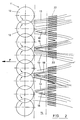
- the eight mower discs 12 shown in Figure 2 comprise, as referred to above, four co-operating pairs, and therefore each pair of discs forms a rearwardly discharging stream of mown grass, as shown by reference 13 in Figure 2. Therefore, having regard to the overall length of the cutter bar 11, it will be apparent that a standing crop which is cut undergoes separation. into four narrow streams 13, which will be more densely packed, than would be the case for a known reciprocating blade type of mower, where the mown crop falls onto the ground directly behind the blade, and extending substantially throughout the length of the blade.
- the combined widths of the four separate streams of mown crop 13 is less than the overall length of the cutter bar 11.
- the four separate streams of mown crop 13 are then guided to a rotary conditioner, which acts in co-operation with a stationary holding or guiding component, and the rotation of the working elements of the conditioner, via its tips, applies a working action to the waxy outer layers of the crop, so as to "bruise” and / or perforate the outer layer, thereby allowing internal moisture to escape, and promoting drying of the conditioned crop after it has been returned to the ground.
- the machine 10 has at least one rotatable conditioning device, which extends transversely of the direction of travel P, and which is rotatably mounted on the frame of the machine so as to rotate about an axis which extends generally parallel to the surface of the ground over which the machine 10 is travelling, in which the conditioning device has working elements extending outwardly of the axis and operative to make working contact with the crop when supplied thereto.
- a first rotatable conditioning device 14 extends transversely of the direction of travel P, and is rotatably mounted on the frame, and has outwardly extending working elements 15 comprising so-called Y tines, which are rigidly mounted on a central rotor 16, and which are operative to make working contact with the crop when supplied thereto.
- a stationary guiding device is also mounted on the frame, and takes the form of a guide plate 17, which guides the mown crop which is rearwardly discharged from between adjacent pairs of mower discs 12, and into working contact with the tips of the tines 15.
- the mown crop which is rearwardly discharged by the mower discs 12 takes the form of four separate and narrowed streams 13, and which would (in the absence of the invention) be applied to the cylindrical outer surface defined by the tips of the working elements 15 in non-uniform manner i.e. whereby less than 100% of the conditioning surface would be utilised in order to condition the grass, and the concentrated streams 13 could exercise excessive drag load between each stream of grass and the guide plate arrangement 17 and the tips of the rotating conditioning elements 15.
- the stationary guide plate 17 includes a diverting arrangement, shown schematically by references 18, which are operative to distribute the streams of mown crop 13 laterally of the direction of travel P, so as to be received substantially throughout the length of the conditioning device 14.
- the streams 13 (which together have combined widths of less than the overall length of the cutter bar 11 and the conditioning device 14) are spread out laterally so as to be distributed substantially uniformly throughout the cylindrical surface defined by the tips of the working elements 15 of the conditioning device 14. This achieves more efficient utilisation of the conditioning surface, but also reduces the thickness of the streams of grass supplied to the conditioner whereby (a) frictional drag forces will be reduced and (b) more of the grass will be exposed to working action.
- the diverting arrangement 18 may comprise simple V-shaped guide plates, provided on the underside of the guide plate arrangement 17, so as to effect required lateral separation of the material in each stream 13.
- the conditioning device 19 preferably comprises a rotating brush type of conditioner, having outwardly extending bristles 20, which apply a more gentle type of "conditioning" action on the crop.
- the guide plate arrangement 17 is projected rearwardly, in undulating manner as shown in Figure 1, so as also to co-operate with, and overlie at least part of the circumference of the second conditioning device 19, with the rearward projection of the guide plate arrangement being shown by reference 21.
- a second diverting arrangement may be provided, and comprising profiled ribs 22, provided on the underside of the cover plate arrangement.
- the preferred embodiment shown in Figures 1 and 2, therefore has first and second rotary conditioning devices 14, 19, with a common guide or holding plate arrangement co-operating therewith (17, 21), and in which a first diverting arrangement 18 is arranged at the upstream end of the guide plate arrangement 17, whereas the second diverting arrangement (formed by profiled ribs 22) is also arranged on the underside of the guide plate arrangement 17 where it overlies the first conditioning device 14.
- the preferred embodiment of agricultural machine according to the invention comprises an integrated mower / conditioner.
- the invention may be applied to a crop conditioner per se, which would be operated as a separate piece of equipment, to pick-up swaths of mown crop having been formed previously by a mower during a separate operation.
- the crop conditioning machine has first and second rotary, conditioning devices
Landscapes
- Life Sciences & Earth Sciences (AREA)
- Environmental Sciences (AREA)
- Harvester Elements (AREA)
Applications Claiming Priority (2)
| Application Number | Priority Date | Filing Date | Title |
|---|---|---|---|
| GB9801236 | 1998-01-22 | ||
| GBGB9801236.2A GB9801236D0 (en) | 1998-01-22 | 1998-01-22 | Crop conditioner |
Publications (1)
| Publication Number | Publication Date |
|---|---|
| EP0931447A1 true EP0931447A1 (fr) | 1999-07-28 |
Family
ID=10825625
Family Applications (1)
| Application Number | Title | Priority Date | Filing Date |
|---|---|---|---|
| EP99300338A Withdrawn EP0931447A1 (fr) | 1998-01-22 | 1999-01-19 | Conditionneur de récolte |
Country Status (2)
| Country | Link |
|---|---|
| EP (1) | EP0931447A1 (fr) |
| GB (1) | GB9801236D0 (fr) |
Citations (5)
| Publication number | Priority date | Publication date | Assignee | Title |
|---|---|---|---|---|
| DE1507224A1 (de) * | 1966-08-18 | 1969-12-04 | Fendt & Co Xaver | Schlepper mit angebautem Maehwerk |
| EP0163123A1 (fr) * | 1981-10-05 | 1985-12-04 | National Research Development Corporation | Dispositif pour entraîner des produits de récolte |
| DK150362B (da) | 1978-03-31 | 1987-02-16 | Nat Res Dev | Apparat til konditionering af afgraede |
| DE4422502C1 (de) * | 1994-06-28 | 1995-06-08 | Krone Bernhard Gmbh Maschf | Landwirtschaftliche Erntemaschine |
| CH688568A5 (de) * | 1996-10-04 | 1997-11-28 | Otto Kurmann Landmaschinen | Aufbereitungseinrichtung fuer landwirtschaftliches Halmgut. |
-
1998
- 1998-01-22 GB GBGB9801236.2A patent/GB9801236D0/en not_active Ceased
-
1999
- 1999-01-19 EP EP99300338A patent/EP0931447A1/fr not_active Withdrawn
Patent Citations (5)
| Publication number | Priority date | Publication date | Assignee | Title |
|---|---|---|---|---|
| DE1507224A1 (de) * | 1966-08-18 | 1969-12-04 | Fendt & Co Xaver | Schlepper mit angebautem Maehwerk |
| DK150362B (da) | 1978-03-31 | 1987-02-16 | Nat Res Dev | Apparat til konditionering af afgraede |
| EP0163123A1 (fr) * | 1981-10-05 | 1985-12-04 | National Research Development Corporation | Dispositif pour entraîner des produits de récolte |
| DE4422502C1 (de) * | 1994-06-28 | 1995-06-08 | Krone Bernhard Gmbh Maschf | Landwirtschaftliche Erntemaschine |
| CH688568A5 (de) * | 1996-10-04 | 1997-11-28 | Otto Kurmann Landmaschinen | Aufbereitungseinrichtung fuer landwirtschaftliches Halmgut. |
Also Published As
| Publication number | Publication date |
|---|---|
| GB9801236D0 (en) | 1998-03-18 |
Similar Documents
| Publication | Publication Date | Title |
|---|---|---|
| US3676988A (en) | Hay-making machine | |
| US4182099A (en) | Impeller mower-conditioner rotor | |
| DE2647739C2 (fr) | ||
| US4398384A (en) | Crop conditioning apparatus and method | |
| US4445313A (en) | Hay cutting machines | |
| US9930832B2 (en) | Mower with reconfigurable crop material ejection | |
| GB2162035A (en) | Wide-cut windrower-conditioner having uniform crop distribution and conditioning | |
| GB1591187A (en) | Crop harvesting machine | |
| US4502267A (en) | Crop engaging apparatus and methods | |
| EP0094036B1 (fr) | Dégageuse de récolte pour une récolteuse de grains | |
| CZ321292A3 (en) | Chaff-cutter | |
| EP0162431B1 (fr) | Machine de récolte | |
| US5070683A (en) | Method and apparatus for mulching of grass, leafage, or similar material | |
| US4545188A (en) | Crop engaging device and method | |
| US3974970A (en) | Forage harvester cutterhead | |
| CA1156531A (fr) | Mecanisme hacheur-alimentateur pour moissonneuse a ecoulement axial | |
| CA1131535A (fr) | Machine agricole | |
| US10448570B2 (en) | System of laying swath of cut crop for improved dry down time and method thereof | |
| GB2092086A (en) | Screw conveyor | |
| DE2653463A1 (de) | Konditioniereinrichtung fuer landwirtschaftliches erntegut | |
| US4274247A (en) | Windrow-forming harvester | |
| EP0853872B1 (fr) | Dispositif pour le traitement des récoltes | |
| EP0931447A1 (fr) | Conditionneur de récolte | |
| US3624987A (en) | Hay cutting and conditioning machine | |
| US3338036A (en) | Hay harvesting machine |
Legal Events
| Date | Code | Title | Description |
|---|---|---|---|
| PUAI | Public reference made under article 153(3) epc to a published international application that has entered the european phase |
Free format text: ORIGINAL CODE: 0009012 |
|
| AK | Designated contracting states |
Kind code of ref document: A1 Designated state(s): AT DE DK FR GB NL |
|
| AX | Request for extension of the european patent |
Free format text: AL;LT;LV;MK;RO;SI |
|
| 17P | Request for examination filed |
Effective date: 20000128 |
|
| AKX | Designation fees paid |
Free format text: AT DE DK FR GB NL |
|
| 17Q | First examination report despatched |
Effective date: 20020320 |
|
| STAA | Information on the status of an ep patent application or granted ep patent |
Free format text: STATUS: THE APPLICATION IS DEEMED TO BE WITHDRAWN |
|
| 18D | Application deemed to be withdrawn |
Effective date: 20020731 |