EP0931480A2 - Computer-Arbeitstisch - Google Patents
Computer-Arbeitstisch Download PDFInfo
- Publication number
- EP0931480A2 EP0931480A2 EP98124111A EP98124111A EP0931480A2 EP 0931480 A2 EP0931480 A2 EP 0931480A2 EP 98124111 A EP98124111 A EP 98124111A EP 98124111 A EP98124111 A EP 98124111A EP 0931480 A2 EP0931480 A2 EP 0931480A2
- Authority
- EP
- European Patent Office
- Prior art keywords
- locking
- work table
- computer work
- table according
- base
- Prior art date
- Legal status (The legal status is an assumption and is not a legal conclusion. Google has not performed a legal analysis and makes no representation as to the accuracy of the status listed.)
- Granted
Links
- 238000004519 manufacturing process Methods 0.000 description 1
- 125000006850 spacer group Chemical group 0.000 description 1
Images


Classifications
-
- A—HUMAN NECESSITIES
- A47—FURNITURE; DOMESTIC ARTICLES OR APPLIANCES; COFFEE MILLS; SPICE MILLS; SUCTION CLEANERS IN GENERAL
- A47B—TABLES; DESKS; OFFICE FURNITURE; CABINETS; DRAWERS; GENERAL DETAILS OF FURNITURE
- A47B21/00—Tables or desks for office equipment, e.g. typewriters, keyboards
- A47B21/007—Tables or desks for office equipment, e.g. typewriters, keyboards with under-desk displays, e.g. displays being viewable through a transparent working surface of the table or desk
- A47B21/0073—Tables or desks for office equipment, e.g. typewriters, keyboards with under-desk displays, e.g. displays being viewable through a transparent working surface of the table or desk liftable above the desk top
Definitions
- the invention relates to a computer work table a plate-like support for one towards them monitor of a computer, the pad around a swivel axis facing the front of the table can be inclined towards the back down.
- a monitor standing on such a support can be used in one suitable for the respective user and to his location adapted to ergonomic needs.
- the object of the invention the measures required for the adjustment to make it as simple and inexpensive as possible.
- Such a pad is the front through the pivot axis default device and behind the two locking devices through the hanging arrangement, so to speak Locking bars supported so that their inclined position changes, if you have the locking devices on the locking bars adjusted. Due to the pivotable attachment of the Locking strips on the table and the pivoting connection of the Latches with the pad they can Follow the pivotal movement of the pad, so to speak, and yourself the respective inclination of the document to adjust.
- the pad in addition to the adjustability of its inclination perpendicular to the swivel axis of the pad to the rear or is adjustable at the front.
- the distance between the user and the monitor changed become.
- the pad in the area of the two locking devices is carried by a mounting rail, which can be moved telescopically on a guide rail sits, the front end of which slants the Pad is pivotally connected to the table and on the locking device for its pivotable connection is pivotally mounted with the pad.
- the table according to the invention can be designed that the pad is adjustable in height and can be inclined at the respective altitude, for example by placing a stationary on each side of the document arranged on the table, extending vertically Row each assigned to an altitude Bearing recesses is arranged, which one with the Underlay associated pivot bearing part is assigned that optionally engaged with the bearing recesses in this way is feasible that in the respective altitude Swivel axis is formed, around which the base can be tilted is.
- the overall computer work table indicated in FIG. 1 1 has on its top a normal worktop serving table top 2, which is arranged fixed is.
- the depth direction T of the work table 1 (the depth direction T extends from front to back) closes seen from the user of the table behind the Table top 2 on a plate-like base 3 on the the monitor belonging to the computer can.
- On both sides of the monitor pad 3 is in the embodiment, one each in the plane of Table top 2, fixed panel area 4 or 5, which is referred to as belonging to the table top and at in contrast to the case shown, this also in one piece can be applied.
- An additional plate 6 is arranged below the table plate 2, the forward towards the user of the desk can be pulled out in the direction of arrow 7. On the Additional plate 6, the computer keyboard can be placed.
- the work table 1 also has a table body on the two in the illustrated embodiment Side walls 8, 9 and two each on one of the side walls fixed foot parts 10, 11 contains, over which the table the floor is standing.
- the monitor pad 3 is around one of the front (User side) facing pivot axis 12 to the rear adjustable at the bottom so that it is in relation to the table top 2 for example that shown in FIGS. 3 and 5 Can assume inclination (the position according to 5 is achieved by an additional height adjustment, which will be explained later).
- the one on the pad 3 standing monitor can thus be tilted accordingly and in a position that can be viewed by the user in a comfortable position Position.
- a high-lying stop device 13 available in Depth direction T and height direction H can be adjusted can.
- the anchor device 13 is of interest here Connection no further.
- the pivot axis 12 can in principle be any pivotable connection of the pad 3 is formed on the table become. It can therefore also be embodied without a body be or, for example, of a pivotable Hanging device are formed with which the pad is hung on the other table.
- the locking bar 14 is stationary with its upper end area, but parallel to the pivot axis 12 of the pad 3 pivotally arranged on the table 1. To do this sits the locking bar 14 above on a table-fixed pivot axis 16, which in the exemplary embodiment on one of the relevant Sidewall 8 upstanding support member 17 arranged is that the table top 2 or the fixed with this connected plate area 4 holds in height.
- the support part 17 is below and above with the help of fastening screws 18 to the side wall 8 or the table top area 4 screwed on.
- Each locking bar 14 is one Locking device 19 assigned to the locking bar 14 in Snap bar longitudinal direction is slidably mounted.
- the Locking device 19 is also parallel to the pivot axis 12 of the monitor pad 3 pivotable with the Document 3 connected.
- the locking device 19 is seated in the exemplary embodiment pivotable on the pivot axis 12 and to the pivot axis 16 parallel hinge pin 20.
- This hinge pin 20 is in the embodiment not directly attached to the monitor base 3, but with one in connection with another adjustment option still to be described guide rail 21 connected, on a support rail carrying the base 3 22 is arranged telescopically.
- the locking device 19 contains an externally operable, between one engaging in one of the recesses 15 and the pad 3 in the respective inclined position holding effective position and one the locking bar 14 releasing inactive position movable Locking element 23. In the horizontal positions according to FIGS. 2 and 4 and in each inclined position thus engages the locking element 23 into one of the recesses 15. Since the Locking device 19 connected to the monitor pad 3 is, this loads over the locking device 19 and thereby About the locking element 23, this is in a the locking recesses 15, on the locking bar 14, which on the Articulation axis 16 depends, so that the weight of the monitor and the pad 3 on the hinge axis 16 in the table body is initiated.
- the locking device 19 makes this Pivotal movement with, the locking device 19 in turn the locking bar with which it is engaged 14 takes along and this slides down. It it is understood that the locking element 23 during this pivoting the monitor pad 3 down in its ineffective Position must be. With this adjustment the locking device 19 also pivots relative to the monitor pad 3 around the hinge pin 20.
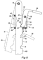
- Fig. 8 are the locking bar 14 and the locking device 19 with solid lines in their horizontal position the corresponding position of the monitor pad 3 and dash-dotted in the inclined position of the base 3 corresponding for example according to FIGS. 3 and 5 Situation indicated.
- the number of locking recesses corresponds to 15, you can see from that assigned to the horizontal position of the base 3 top recess, the number of possible Oblique positions of the base 3.
- the locking bar 14 can thus also be longer than in FIG. 6 and more than the ones shown Form locking recesses 15.
- the locking element 23 is in the direction of its from FIG. 8 resulting effective position by a spring force (Coil spring 24) applied so that it against the Snap bar 14 and in the respectively set Inclination of the base 3 in the relevant recess 15 is pressed.
- a spring force Coil spring 24
- the locking element 23 sits on an actuator 25, the pivotally mounted for adjusting the locking element 23 is.
- the actuator 25 is expedient mounted on the hinge pin 20 already mentioned, about the entire locking device 19 pivoted with the Monitor pad 3 is connected.
- the actuator 25 also has a handle 26 accessible from the outside on that for pivoting the actuator 25 and the gripped by this latching element 23 carried by hand becomes.
- the actuator 25 provides one on the Hinge pin 20 mounted two-armed lever one lever arm of which the handle 26 is arranged and whose other lever arm carries the locking element 23.
- the actuators 25 of the However, two locking devices 19 could also have one Actuating rod running in the longitudinal direction L of the table or the like. be connected to one another so that one for the operation would only require one hand.
- the locking recesses 15 are on the side of the locking bar 14 arranged and on this side of the bar for entry of the adjacent locking element 23 open.
- the series of locking recesses 15 on the seen from the user of the table rear-facing rear 29 of the locking bar 14 is formed.
- the locking bar 14 is advantageously made of flat material manufactured, the back 29 of one of the is formed on both narrow sides.
- the locking device 19 contains one of the locking bar 14 penetrated guide recess 30.
- the guide recess 30 is on the having the recesses 15 Last side 29 by the actuator 25 with the Locking element 23 and on the opposite side a guide stop arrangement 31 of the latching device 19 limited.
- the actuator 25 forms two angular mutually facing contact surfaces 32, 33, of which the contact surface 32 facing the locking element 23 in the effective position of the locking element 23 and the other Contact surface 33 in the from the relevant recess 15 swung out ineffective position of the locking element abuts on the facing locking bar side 29.
- the latching device 19 also has a device housing 34 flat shape with two locking bars 14 between receiving housing plates 35, 36.
- the two housing plates 35, 36 are parallel to the flat sides the locking bar 14 arranged.
- the actuator 25 engages on the one hand the locking bar 14 between the two Housing plates 35, 36 while the guide stop assembly 31 on the other hand, the locking bar 14 between the two Housing plates 35, 36 is arranged. This is what it is about themselves in the exemplary embodiment in the guide stop arrangement 31 um connecting to the two plates 35, 36 Connecting bolts 37, 38 seated spacers 39, 40.
- the hinge pin 20 already mentioned passes through the two housing plates 35, 36.
- the spring 24 is also between the two Housing plates 35, 36 and is supported on the one hand Extension 41 arranged in the vicinity of the locking element 23 of the actuator 25 and on the other hand at an between the two housing plates 35, 36 arranged Housing section 42 from.
- the actuator 25 is designed and arranged so that its handle 26 for pivoting the locking element 23rd pressed out of the relevant recess 15 upwards must become.
- the monitor pad 3 is not only in the mentioned Way inclinable, but can also be perpendicular Swivel axis 12 of the pad 3 towards the rear or towards the front be adjusted. This corresponds to in their horizontal position located monitor pad 3 an adjustment in Depth direction T.
- the monitor pad 3 When swiveling the monitor pad 3 about the swivel axis 12 in the swivel direction S (see Fig. 3) is the pad 3 together with the two Rails 21, 22 pivoted, the guide rail 21 protrudes from the pivot axis 12 to the rear.
- the latching device 29 pivotally mounted.
- the monitor pad 3 is in a suitable manner on the respective mounting rail 22 attached. Serve for this at Embodiment on the one hand riveted to the mounting rail 22 and on the other hand to the underside of the pad 3 screwed mounting brackets 43.
- the mounting rail 22 is in the embodiment on the Guide rail 21 attached and has a C-like Cross section facing the respective locking device 19 C slot 44.
- the hinge pin 20, on the the latching device 19 can be pivoted with the base 3 connected, reaches through the C-slot 44 and is in appropriately set on the guide rail 21.
- the one formed by the guide rail 21 and the mounting rail 22 Rail arrangement is a locking device to determine the respective longitudinal position of the mounting rail 22 assigned to the guide rail 21.
- the Guide rail have a series of holes 45, wherein the row of holes a locking member arranged on the mounting rail 22 46, expediently assigned a locking bolt is in the respective longitudinal position of the mounting rail 22 with the adjacent hole 45 of the row of holes in Intervention can be brought.
- the locking member 46 can thus optionally brought into engagement with the holes 45 be, so that the number of adjustment options in Depth direction T corresponds to the number of holes 45.
- the Locking member 46 can by a not shown Spring device in the direction of its engaging in a hole 45 Be engaged position. In the illustrated Trap is the locking member 46 with a handle 47 provided. To pull out the locking member 46 out of the hole 45 in question on the handle 47 the spring force.
- adjusting in the depth direction T it remains in the inclined positions with the locking bar 14 latching locking device 19 in place since it is over the hinge pin 20 is attached to the guide rail 21.
- the monitor pad 3 is also still in the height direction H adjustable. It can be in any altitude be described as slanted. Furthermore is an adjustment in the depth direction at any altitude T possible.
- the bearing recesses 48 the shape of holes. In this Trap the pivot bearing part 49 of one in the holes matching pivot bearing pin formed.
- the pad 3 can accordingly in the respective altitude hung pivotably on the bearing recesses 48 be, in the embodiment, the base 3rd not directly, but via the guide rails 21 height adjustable is attached.
- the bearing recesses 48 to the opposite Side of the monitor pad 3 directed. Furthermore are the front end portions of the two on one side the pad 3 arranged guide rails 21 over a Connecting pipe 50 connected to each other, wherein in the both end regions of the connecting tube 50 each the pivot bearing part in question forming pivot bearing pin 51 slidably mounted in the longitudinal direction of the tube is.
- the respective pivot bearing pin 51 is between an advanced one to the desired altitude the corresponding bearing recess 3 engaging 48 Position and one in front of the row of bearing recesses 48 position located from the outside arranged.
- the connecting pipe 50 have a recess 52 on its outer surface, by the one connected to the pivot bearing pin 51 handle 53 protrudes outward so that it can be gripped by hand can be.
- the pivot bearing pin 51 is also through a spring force (spring device mounted in the connecting tube 50 54) towards its engaged position acted out so that it is in the respective altitude corresponding bearing recess 48 is held.
- the pivot pin 51 is used to adjust the height by means of the handle 53 from the relevant bearing recess 48 pulled out.
- the bearing recesses 48 are advantageously on one the table top 2 supporting part 55 holding the height arranged.
- This support member 55 is located in the depth direction T before the support part already described 17.
- Das Support part 55 is at the bottom of the relevant side wall 8 and attached to the top of the table top 2, being at Embodiment also attached to the plate area 4 above is. Again the upper and lower fastening takes place using fastening screws 56.
Landscapes
- Tables And Desks Characterized By Structural Shape (AREA)
- Accommodation For Nursing Or Treatment Tables (AREA)
- Pharmaceuticals Containing Other Organic And Inorganic Compounds (AREA)
- Saccharide Compounds (AREA)
Abstract
Description
- Fig. 1
- einen Computer-Arbeitstisch in schematischer Schrägansicht von vorne, wobei sich die Unterlage für den Monitor in der Ebene der Tischplatte befindet,
- Fig. 2
- die Tischplatte und die plattenartige Unterlage für den Monitor im Querschnitt gemäß der Schnittlinie II-II, wobei die Unterlage in der Ebene der Tischplatte angeordnet ist,
- Fig. 3
- die Anordnung nach Fig. 2, wobei die Unterlage aus ihrer in der Ebene der Tischplatte befindlichen Horizontalstellung in eine hinten nach unten abgesenkte Schrägstellung überführt worden ist,
- Fig. 4
- wiederum die Tischplatte und die Unterlage für den Monitor im entsprechenden Querschnitt, wobei die Unterlage unter Beibehaltung ihrer zur Tischplatte parallelen Horizontalstellung insgesamt abgesenkt worden ist,
- Fig. 5
- wiederum die gleiche Anordnung von Tischplatte und Monitor-Unterlage im Querschnitt, wobei die Unterlage mit Bezug auf ihre aus Fig. 4 hervorgehenden Stellung nach hinten unten schräggestellt worden ist,
- Fig. 6
- den Arbeitstisch nach Fig. 1 in Schrägansicht von hinten unten gesehen, wobei nur einer der beiden seitlichen Bereiche der Unterlage zusammen mit den zugehörigen Beschlagteilen und den benachbarten Schreibtischteilen dargestellt ist, so daß die Unterlage und die Tischplatte etwa gemäß der Schnittlinie II-II in Fig. 1 geschnitten sind, und wobei sich die Unterlage in einer der Fig. 4 entsprechenden Position befindet,
- Fig. 7
- die aus Fig. 6 hervorgehende Anordnung in Rückansicht gemäß Pfeil VII, wobei die Unterlage, der seitlich neben der Unterlage angeordnete Tischplattenbereich, die Tisch-Seitenwand, die Tragschiene und die Führungsschiene der Übersichtlichkeit wegen einer Schnittdarstellung entsprechend schraffiert worden sind, und
- Fig. 8
- die aus den Fig. 6 und 7 hervorgehende Rastleiste mit an ihr sitzender Rastvorrichtung in gesonderter Darstellung, wobei vom Gehäuse der Rastvorrichtung die dem Betrachter zugewandte Gehäuseplatte entfernt worden ist.
Claims (20)
- Computer-Arbeitstisch mit einer plattenartigen Unterlage für einen auf sie zu stellenden Monitor eines Computers, wobei die Unterlage um eine der Vorderseite des Tisches zugewandte Schwenkachse nach hinten unten schrägstellbar ist, dadurch gekennzeichnet, daß beiderseits der Unterlage (3) jeweils eine sich von oben nach unten erstreckende, oben ortsfest parallelachsig zur Schwenkachse (12) der Unterlage (3) verschwenkbar am Tisch angeordnete Rastleiste (14) mit einer Reihe von jeweils einer Schrägstellung der Unterlage (3) zugeordneten Rastausnehmungen (15) vorhanden ist, an der eine parallelachsig zur Schwenkachse (12) der Unterlage (3) verschwenkbar mit der Unterlage (3) verbundene Rastvorrichtung (19) in Rastleisten-Längsrichtung verschiebbar gelagert ist, die ein von außen her betätigbares, zwischen einer in eine der Rastausnehmungen (15) eingreifenden und die Unterlage (3) in der jeweiligen Schrägstellung haltenden wirksamen Stellung und einer die Rastleiste (14) freigebenden unwirksamen Stellung bewegbares Rastelement (23) enthält.
- Computer-Arbeitstisch nach Anspruch 1, dadurch gekennzeichnet, daß das Rastelement (23) in Richtung auf seine wirksame Stellung hin durch eine Federkraft beaufschlagt ist.
- Computer-Arbeitstisch nach Anspruch 1 oder 2, dadurch gekennzeichnet, daß die Rastvorrichtung (19) ein das Rastelement (23) tragendes Betätigungsglied (25) enthält, das zum Verstellen des Rastelements (23) schwenkbar gelagert ist.
- Computer-Arbeitstisch nach Anspruch 3, dadurch gekennzeichnet, daß das Betätigungsglied (25) auf einem Gelenkbolzen (20) schwenkbar gelagert ist, über den die Rastvorrichtung (19) verschwenkbar mit der Unterlage (3) verbunden ist.
- Computer-Arbeitstisch nach Anspruch 3 oder 4, dadurch gekennzeichnet, daß die Rastvorrichtung (19) eine von der Rastleiste (14) durchgriffene Führungsausnehmung (30) bildet, die an der die Rastausnehmungen (15) aufweisenden Leistenseite (29) durch das Betätigungsglied (25) mit dem Rastelement (23) und an der entgegengesetzten Seite durch eine Führungsanschlaganordnung (31) der Rastvorrichtung (19) begrenzt wird.
- Computer-Arbeitstisch nach Anspruch 5, dadurch gekennzeichnet, daß die Rastvorrichtung (19) ein Vorrichtungsgehäuse (34) flacher Gestalt mit zwei die Rastleiste (14) zwischen sich aufnehmenden Gehäuseplatten (35, 36) aufweist, wobei das Betätigungsglied (25) einerseits der Rastleiste (14) zwischen die beiden Gehäuseplatten (35, 36) greift und die Führungsanschlaganordnung (31) andererseits der Rastleiste (14) zwischen den beiden Gehäuseplatten (35, 36) angeordnet ist.
- Computer-Arbeitstisch nach einem der Ansprüche 2 bis 6, dadurch gekennzeichnet, daß die Rastausnehmungen (15) und das Rastelement (23) so geformt sind, daß das Rastelement (23) beim Anheben der Unterlage (3) aus einer Schrägstellung entgegen der Federkraft selbsttätig aus der wirksamen Stellung bewegt wird.
- Computer-Arbeitstisch nach einem der Ansprüche 1 bis 7, dadurch gekennzeichnet, daß die Unterlage (3) rechtwinkelig zur Schwenkachse (12) der Unterlage (3) nach hinten bzw. vorne hin verstellbar ist.
- Computer-Arbeitstisch nach Anspruch 8, dadurch gekennzeichnet, daß die Unterlage (3) im Bereich der beiden Rastvorrichtungen (19) jeweils von einer Tragschiene (22) getragen wird, die teleskopartig verschiebbar an einer Führungsschiene (21) sitzt, deren vorderer Endbereich zum Schrägstellen der Unterlage (3) verschwenkbar mit dem Tisch verbunden ist und an der die Rastvorrichtung (19) zu ihrer verschwenkbaren Verbindung mit der Unterlage (3) verschwenkbar gelagert ist.
- Computer-Arbeitstisch nach Anspruch 9, dadurch gekennzeichnet, daß die Tragschiene (22) auf die Führungsschiene (21) aufgesteckt ist und einen C-artigen Querschnitt aufweist, wobei der Gelenkbolzen (20), über den die Rastvorrichtung (19) verschwenkbar mit der Unterlage (3) verbunden ist, durch den C-Schlitz (44) der Tragschiene (22) greift und mit der Führungsschiene (21) verbunden ist.
- Computer-Arbeitstisch nach Anspruch 9 oder 10, dadurch gekennzeichnet, daß der von der Tragschiene (22) und der Führungsschiene (21) gebildeten Schienenanordnung eine Feststelleinrichtung zum Feststellen der jeweiligen Längslage der Tragschiene (22) an der Führungsschiene (21) zugeordnet ist.
- Computer-Arbeitstisch nach Anspruch 11, dadurch gekennzeichnet, daß die Führungsschiene (21) eine Lochreihe (45) aufweist, der ein an der Tragschiene (22) angeordnetes, wahlweise mit den Löchern (45) der Lochreihe in Eingriff bringbares Feststellglied (46) zugeordnet ist.
- Computer-Arbeitstisch nach Anspruch 12, dadurch gekennzeichnet, daß das Feststellglied (46) durch eine Federeinrichtung in Richtung auf seine Eingriffsstellung hin beaufschlagt ist.
- Computer-Arbeitstisch nach einem der Ansprüche 1 bis 13, dadurch gekennzeichnet, daß die Unterlage (3) in der Höhe verstellbar und in der jeweiligen Höhenlage schrägstellbar ist.
- Computer-Arbeitstisch nach Anspruch 14, dadurch gekennzeichnet, daß beiderseits der Unterlage (3) jeweils eine ortsfest am Tisch angeordnete, sich in Höhenrichtung erstreckende Reihe von jeweils einer Höhenlage zugeordneten Lagerausnehmungen (48) angeordnet ist, denen ein mit der Unterlage (3) verbundenes Schwenklagerteil (49) zugeordnet ist, das wahlweise mit den Lagerausnehmungen (48) derart in Eingriff bringbar ist, daß in der jeweiligen Höhenlage eine Schwenkachse (12) gebildet wird, um die die Unterlage (3) schrägstellbar ist.
- Computer-Arbeitstisch nach Anspruch 15, dadurch gekennzeichnet, daß am vorderen Endbereich der beiden Führungsschienen (21) jeweils ein Schwenklagerteil (49) angeordnet ist.
- Computer-Arbeitstisch nach Anspruch 15 oder 16, dadurch gekennzeichnet, daß die Lagerausnehmungen (48) die Gestalt von Bohrungen aufweisen und das Schwenklagerteil (49) von einem Schwenklagerbolzen (51) gebildet wird.
- Computer-Arbeitstisch nach Anspruch 17, dadurch gekennzeichnet, daß die vorderen Endbereiche der beiden Führungsschienen (21) über ein Verbindungsrohr (50) miteinander verbunden sind, in dessen Endbereichen jeweils ein Schwenklagerbolzen (51) in Rohr-Längsrichtung zwischen einer vorgeschobenen, in die jeweilige Lagerausnehmung (48) eingreifenden Stellung und einer vor der jeweiligen Reihe von Lagerausnehmungen (48) befindlichen Stellung von außen her verschieblich gelagert ist.
- Computer-Arbeitstisch nach Anspruch 18, dadurch gekennzeichnet, daß der Schwenklagerbolzen (51) durch eine Federkraft in Richtung auf seine Eingriffstellung hin beaufschlagt ist.
- Computer-Arbeitstisch nach einem der Ansprüche 15 bis 19, dadurch gekennzeichnet, daß die Lagerausnehmungen (48) an einem die Tischplatte (2) in der Höhe haltenden Stützteil (55) angeordnet sind.
Applications Claiming Priority (2)
| Application Number | Priority Date | Filing Date | Title |
|---|---|---|---|
| DE19801210A DE19801210A1 (de) | 1998-01-15 | 1998-01-15 | Computer-Arbeitstisch |
| DE19801210 | 1998-01-15 |
Publications (3)
| Publication Number | Publication Date |
|---|---|
| EP0931480A2 true EP0931480A2 (de) | 1999-07-28 |
| EP0931480A3 EP0931480A3 (de) | 2002-05-08 |
| EP0931480B1 EP0931480B1 (de) | 2005-12-07 |
Family
ID=7854635
Family Applications (1)
| Application Number | Title | Priority Date | Filing Date |
|---|---|---|---|
| EP98124111A Expired - Lifetime EP0931480B1 (de) | 1998-01-15 | 1998-12-18 | Computer-Arbeitstisch |
Country Status (3)
| Country | Link |
|---|---|
| EP (1) | EP0931480B1 (de) |
| AT (1) | ATE311788T1 (de) |
| DE (2) | DE19801210A1 (de) |
Cited By (1)
| Publication number | Priority date | Publication date | Assignee | Title |
|---|---|---|---|---|
| CN116749134A (zh) * | 2023-04-25 | 2023-09-15 | 南京环盟科技有限责任公司 | 一种多功能一体化工作台 |
Families Citing this family (1)
| Publication number | Priority date | Publication date | Assignee | Title |
|---|---|---|---|---|
| DE10120106B4 (de) * | 2001-04-23 | 2004-11-04 | Erich Keller Ag | Arbeitstisch |
Family Cites Families (2)
| Publication number | Priority date | Publication date | Assignee | Title |
|---|---|---|---|---|
| DE19500525C2 (de) * | 1995-01-11 | 1999-07-29 | Moll Sys & Funktions Moebel | Tischartiges Möbelstück mit einer plattenartigen Unterlage für einen Monitor |
| DE29711779U1 (de) * | 1997-07-05 | 1997-09-11 | Moll System- und Funktions-Möbel GmbH, 73344 Gruibingen | Haltevorrichtung zum Halten eines Monitors an einem Tisch o.dgl. Möbelstück |
-
1998
- 1998-01-15 DE DE19801210A patent/DE19801210A1/de not_active Withdrawn
- 1998-12-18 EP EP98124111A patent/EP0931480B1/de not_active Expired - Lifetime
- 1998-12-18 AT AT98124111T patent/ATE311788T1/de not_active IP Right Cessation
- 1998-12-18 DE DE59813261T patent/DE59813261D1/de not_active Expired - Fee Related
Non-Patent Citations (1)
| Title |
|---|
| None |
Cited By (1)
| Publication number | Priority date | Publication date | Assignee | Title |
|---|---|---|---|---|
| CN116749134A (zh) * | 2023-04-25 | 2023-09-15 | 南京环盟科技有限责任公司 | 一种多功能一体化工作台 |
Also Published As
| Publication number | Publication date |
|---|---|
| DE59813261D1 (de) | 2006-01-12 |
| EP0931480A3 (de) | 2002-05-08 |
| ATE311788T1 (de) | 2005-12-15 |
| DE19801210A1 (de) | 1999-07-22 |
| EP0931480B1 (de) | 2005-12-07 |
Similar Documents
| Publication | Publication Date | Title |
|---|---|---|
| DE60205760T2 (de) | Verstellbare tastaturfeldträgeranordnung | |
| EP0022933B1 (de) | Sitz mit neigungsverstellbarer Sitzplatte und neigungsverstellbarer Rückenlehne | |
| EP1492702B1 (de) | Kopfstütze für einen sitz | |
| DE29906637U1 (de) | Computertisch | |
| DE3612868A1 (de) | Bueromoebeltisch | |
| EP0958765B1 (de) | Armstütze, insbesondere für Büro- und Drehstühle | |
| EP2023774A1 (de) | Tischverkabelungsklappe | |
| AT399120B (de) | Einrichtung zum schneiden von fliesen und/oder platten | |
| EP0207916B1 (de) | Beschlag, insbesondere für Bürostühle | |
| EP0931480B1 (de) | Computer-Arbeitstisch | |
| EP1637053A1 (de) | Möbel, insbesondere Arbeitstisch | |
| DE19522183C2 (de) | Arbeitstisch für ein insbesondere medizinisches oder dentales Labor | |
| DE4310454C1 (de) | Armlehne für Fahrzeugsitze | |
| EP1284710B1 (de) | Gebärstuhl | |
| EP0948274A1 (de) | Arbeitstisch, insbesondere computertisch | |
| DE29809099U1 (de) | Armstütze, insbesondere für Büro- und Drehstühle | |
| EP0580077B1 (de) | Tisch mit einer beweglichen Arbeitsplatte | |
| EP0263999B1 (de) | Ablagevorrichtung zur Aufnahme einer Schreibtastatur | |
| DE29518585U1 (de) | Rollgestell für Lasten | |
| DE8709872U1 (de) | EDV-Geräteträger mit einem Tastaturenhalter | |
| DE4334241C2 (de) | Arbeitstisch, insbesondere Schreib- und/oder Computertisch | |
| DE102006019624B4 (de) | Höhenverstellbarer Tisch | |
| DE9412060U1 (de) | Rollgestell für Lasten | |
| DE3202847A1 (de) | "justiervorrichtung zum einstellen der hoehe und/oder neigung einer tragkonstruktion fuer bueroarbeitsgeraete" | |
| DE29708485U1 (de) | Computer-Arbeitstisch |
Legal Events
| Date | Code | Title | Description |
|---|---|---|---|
| PUAI | Public reference made under article 153(3) epc to a published international application that has entered the european phase |
Free format text: ORIGINAL CODE: 0009012 |
|
| AK | Designated contracting states |
Kind code of ref document: A2 Designated state(s): AT BE CH CY DE DK ES FI FR GB GR IE IT LI LU MC NL PT SE |
|
| AX | Request for extension of the european patent |
Free format text: AL;LT;LV;MK;RO;SI |
|
| PUAL | Search report despatched |
Free format text: ORIGINAL CODE: 0009013 |
|
| AK | Designated contracting states |
Kind code of ref document: A3 Designated state(s): AT BE CH CY DE DK ES FI FR GB GR IE IT LI LU MC NL PT SE |
|
| AX | Request for extension of the european patent |
Free format text: AL;LT;LV;MK;RO;SI |
|
| RIC1 | Information provided on ipc code assigned before grant |
Free format text: 7A 47B 21/00 A, 7A 47B 21/03 B |
|
| 17P | Request for examination filed |
Effective date: 20020626 |
|
| AKX | Designation fees paid |
Designated state(s): AT BE CH DE ES FR IT LI LU NL SE |
|
| GRAP | Despatch of communication of intention to grant a patent |
Free format text: ORIGINAL CODE: EPIDOSNIGR1 |
|
| GRAS | Grant fee paid |
Free format text: ORIGINAL CODE: EPIDOSNIGR3 |
|
| GRAA | (expected) grant |
Free format text: ORIGINAL CODE: 0009210 |
|
| AK | Designated contracting states |
Kind code of ref document: B1 Designated state(s): AT BE CH DE ES FR IT LI LU NL SE |
|
| PG25 | Lapsed in a contracting state [announced via postgrant information from national office to epo] |
Ref country code: NL Free format text: LAPSE BECAUSE OF FAILURE TO SUBMIT A TRANSLATION OF THE DESCRIPTION OR TO PAY THE FEE WITHIN THE PRESCRIBED TIME-LIMIT Effective date: 20051207 Ref country code: IT Free format text: LAPSE BECAUSE OF FAILURE TO SUBMIT A TRANSLATION OF THE DESCRIPTION OR TO PAY THE FEE WITHIN THE PRE;WARNING: LAPSES OF ITALIAN PATENTS WITH EFFECTIVE DATE BEFORE 2007 MAY HAVE OCCURRED AT ANY TIME BEFORE 2007. THE CORRECT EFFECTIVE DATE MAY BE DIFFERENT FROM THE ONE RECORDED.SCRIBED TIME-LIMIT Effective date: 20051207 Ref country code: ES Free format text: LAPSE BECAUSE OF FAILURE TO SUBMIT A TRANSLATION OF THE DESCRIPTION OR TO PAY THE FEE WITHIN THE PRESCRIBED TIME-LIMIT Effective date: 20051207 |
|
| PGFP | Annual fee paid to national office [announced via postgrant information from national office to epo] |
Ref country code: AT Payment date: 20051207 Year of fee payment: 8 |
|
| REG | Reference to a national code |
Ref country code: CH Ref legal event code: NV Representative=s name: TROESCH SCHEIDEGGER WERNER AG Ref country code: CH Ref legal event code: EP |
|
| PG25 | Lapsed in a contracting state [announced via postgrant information from national office to epo] |
Ref country code: BE Free format text: LAPSE BECAUSE OF NON-PAYMENT OF DUE FEES Effective date: 20051231 |
|
| REF | Corresponds to: |
Ref document number: 59813261 Country of ref document: DE Date of ref document: 20060112 Kind code of ref document: P |
|
| PG25 | Lapsed in a contracting state [announced via postgrant information from national office to epo] |
Ref country code: LU Free format text: LAPSE BECAUSE OF NON-PAYMENT OF DUE FEES Effective date: 20060207 |
|
| PG25 | Lapsed in a contracting state [announced via postgrant information from national office to epo] |
Ref country code: SE Free format text: LAPSE BECAUSE OF FAILURE TO SUBMIT A TRANSLATION OF THE DESCRIPTION OR TO PAY THE FEE WITHIN THE PRESCRIBED TIME-LIMIT Effective date: 20060307 |
|
| NLV1 | Nl: lapsed or annulled due to failure to fulfill the requirements of art. 29p and 29m of the patents act | ||
| PLBE | No opposition filed within time limit |
Free format text: ORIGINAL CODE: 0009261 |
|
| STAA | Information on the status of an ep patent application or granted ep patent |
Free format text: STATUS: NO OPPOSITION FILED WITHIN TIME LIMIT |
|
| PGFP | Annual fee paid to national office [announced via postgrant information from national office to epo] |
Ref country code: DE Payment date: 20061110 Year of fee payment: 9 |
|
| 26N | No opposition filed |
Effective date: 20060908 |
|
| EN | Fr: translation not filed | ||
| PGFP | Annual fee paid to national office [announced via postgrant information from national office to epo] |
Ref country code: CH Payment date: 20070222 Year of fee payment: 9 |
|
| PG25 | Lapsed in a contracting state [announced via postgrant information from national office to epo] |
Ref country code: AT Free format text: LAPSE BECAUSE OF NON-PAYMENT OF DUE FEES Effective date: 20061218 |
|
| BERE | Be: lapsed |
Owner name: MOLL SYSTEM- UND FUNKTIONS-MOBEL G.M.B.H. Effective date: 20051231 |
|
| PG25 | Lapsed in a contracting state [announced via postgrant information from national office to epo] |
Ref country code: FR Free format text: LAPSE BECAUSE OF FAILURE TO SUBMIT A TRANSLATION OF THE DESCRIPTION OR TO PAY THE FEE WITHIN THE PRESCRIBED TIME-LIMIT Effective date: 20070126 |
|
| REG | Reference to a national code |
Ref country code: CH Ref legal event code: PL |
|
| PG25 | Lapsed in a contracting state [announced via postgrant information from national office to epo] |
Ref country code: LI Free format text: LAPSE BECAUSE OF NON-PAYMENT OF DUE FEES Effective date: 20071231 Ref country code: FR Free format text: LAPSE BECAUSE OF FAILURE TO SUBMIT A TRANSLATION OF THE DESCRIPTION OR TO PAY THE FEE WITHIN THE PRESCRIBED TIME-LIMIT Effective date: 20051231 Ref country code: DE Free format text: LAPSE BECAUSE OF NON-PAYMENT OF DUE FEES Effective date: 20080701 Ref country code: CH Free format text: LAPSE BECAUSE OF NON-PAYMENT OF DUE FEES Effective date: 20071231 |
|
| PG25 | Lapsed in a contracting state [announced via postgrant information from national office to epo] |
Ref country code: FR Free format text: LAPSE BECAUSE OF FAILURE TO SUBMIT A TRANSLATION OF THE DESCRIPTION OR TO PAY THE FEE WITHIN THE PRESCRIBED TIME-LIMIT Effective date: 20051207 |