EP0931488A2 - Improved Playpen - Google Patents
Improved Playpen Download PDFInfo
- Publication number
- EP0931488A2 EP0931488A2 EP98118822A EP98118822A EP0931488A2 EP 0931488 A2 EP0931488 A2 EP 0931488A2 EP 98118822 A EP98118822 A EP 98118822A EP 98118822 A EP98118822 A EP 98118822A EP 0931488 A2 EP0931488 A2 EP 0931488A2
- Authority
- EP
- European Patent Office
- Prior art keywords
- playpen
- socket
- playpen according
- protuberance
- pair
- Prior art date
- Legal status (The legal status is an assumption and is not a legal conclusion. Google has not performed a legal analysis and makes no representation as to the accuracy of the status listed.)
- Withdrawn
Links
Images


Classifications
-
- A—HUMAN NECESSITIES
- A47—FURNITURE; DOMESTIC ARTICLES OR APPLIANCES; COFFEE MILLS; SPICE MILLS; SUCTION CLEANERS IN GENERAL
- A47D—FURNITURE SPECIALLY ADAPTED FOR CHILDREN
- A47D13/00—Other nursery furniture
- A47D13/06—Children's play- pens
-
- A—HUMAN NECESSITIES
- A47—FURNITURE; DOMESTIC ARTICLES OR APPLIANCES; COFFEE MILLS; SPICE MILLS; SUCTION CLEANERS IN GENERAL
- A47D—FURNITURE SPECIALLY ADAPTED FOR CHILDREN
- A47D9/00—Cradles ; Bassinets
- A47D9/02—Cradles ; Bassinets with rocking mechanisms
- A47D9/053—Cradles ; Bassinets with rocking mechanisms with curved rocking member
-
- Y—GENERAL TAGGING OF NEW TECHNOLOGICAL DEVELOPMENTS; GENERAL TAGGING OF CROSS-SECTIONAL TECHNOLOGIES SPANNING OVER SEVERAL SECTIONS OF THE IPC; TECHNICAL SUBJECTS COVERED BY FORMER USPC CROSS-REFERENCE ART COLLECTIONS [XRACs] AND DIGESTS
- Y10—TECHNICAL SUBJECTS COVERED BY FORMER USPC
- Y10T—TECHNICAL SUBJECTS COVERED BY FORMER US CLASSIFICATION
- Y10T403/00—Joints and connections
- Y10T403/60—Biased catch or latch
- Y10T403/606—Leaf spring
Definitions
- the present invention relates to a playpen, and more particularly to an improved playpen having a pair of pivotable rocker device enabling the playpen to convert into a rocking cradle easily and vice versa.
- the main structure of conventional playpens includes four top rails contiguously linked by four top corner brackets, four bottom rails contiguously linked by four bottom corner brackets, four columns respectively extending between paired top and bottom corner brackets, a base extending between the bottom side rails and a mesh wall extending around the four columns.
- the top side rails and bottom side rails may be articulated at midpoints thereof to facilitate easy and compact storage of the playpen when not in use.
- the bottom corner brackets of the conventional playpens also function as simple feet which, although providing stability do not allow the playpen to be rocked when a baby or infant therein is tired and should sleep.
- the parents In order to coax an infant into sleeping, the parents usually cradle the infant in their arms. However, the parents' arms ache after five or ten minutes of this action. When the parent places the infant on the floor of the conventional playpen, the infant usually wakes up and cries which is inconvenient and distressing.
- the present invention has arisen to mitigate and/or obviate the disadvantage of the conventional playpen.
- an improved playpen which can be transformed into a rocking cradle.
- the main characteristic of the present invention is to pivot a pair of rocker devices to support the playpen. Therefore, the playpen becomes the rocking cradle and it is easier for the parents to coax an infant to sleep comfortably in that type of the playpen. More important, the rocker devices can be readily pivoted to the first configuration whereby the rocking cradle is converted back to the conventional playpen.
- the rocking devices In a first position, the rocking devices are pivoted to rest at a point above a bottom face of the bottom corner brackets.
- the arcuate tubes In a second position, the arcuate tubes are pivoted downward such that they extend below the bottom faces of the bottom corner brackets whereby the playpen becomes a rocking cradle.
- the rocking cradle can be returned to function as the playpen by reversing the procedure described.
- a playpen (1) convertible into a rocking cradle includes four top corner brackets (10), four top rails (11) each connected between two corresponding top corner brackets (10), four columns (12) each having a top end secured to a corresponding top corner bracket (10) and extending downward therefrom, four bottom corner brackets (20) attached to a second end of a respective one of the four columns (12), four bottom rails (13) each connected between two corresponding bottom brackets (20) and a pair of rocking devices each respectively attached to two opposed pairs of the bottom corner brackets (20).
- the pair of rocker devices are identical, thus the components thereof and attachment to the respective bottom corner brackets (20) refer to a single unit from hereon. Similarly, the four bottom corner brackets (20) are identical, so only a single unit is referred to from hereon.
- the bottom corner bracket (20) includes a top plate and a hollow portion extending downward from the top plate. Two recesses are contained in a top face of the top plate and are perpendicular to each other. One end of a respective one of the bottom rails (13) is received in each of the two recesses of the bottom corner brackets (20).
- a tubular projection is integrally formed within the hollow portion of the bottom corner bracket (20) and contains a passage (21) therein extending up through the top plate.
- the passage (21) has a longitudinal axis perpendicular to the longitudinal axes of the bottom rails (13) received in the recess of the bottom corner bracket (20).
- An integral platform (22) is formed in a lower portion of the passage (21) and divides the passage (21) into an upper part and a lower part.
- the platform (22) contains a screw hole (221) in a center thereof.
- the upper part of the passage (21) is sized to snugly received therein the lower end of the column (12) such that a bottom face thereof abuts the top face of the platform (22).
- a web (23) extends from the outer periphery of the tubular projection to the inner face of the hollow portion of the bottom corner bracket (20).
- Each rocker device includes a pair of couplings (30), a pair of pivots (40) and an arcuate tube (50).
- the couplings (30) are identical, only one unit is described from hereon.
- the coupling (30) is substantially shaped as " ⁇ " when viewed from a horizontal cross-sectional and is divided into a first socket (31) integrally formed with a second socket (36) adjacent thereto.
- the first socket (31) has a circumferential wall containing an opening at the top thereof and a base (32) is integrally formed at a bottom thereof.
- a top face of the base (32) has formed thereon a rod (33) which is upright.
- the bottom face of the base (32) contains therein a counterbore connecting to a bore extending upward through the rod (33).
- a cylindrical space is contained between the inner periphery of the circumferential wall and the rod (33).
- the cylindrical space of the first socket (31) is sized to receive the lower portion of the tubular projection.
- a bolt (301) extends through the counterbore and the bore of the first socket (31) to threadedly engage with the platform (22) of the bottom corner bracket (20).
- a long notch (34) is longitudinally contained in the circumferential wall of the first socket (31) and is in communication with the opening thereof. The long notch (34) is sized to matingly engage with the web (23) of the bottom corner bracket (20).
- a short notch (35) is also contained in the circumferential wall of the first socket (31) and is in communication with the opening thereof.
- a screw extends through the short notch (35) and the sidewall of the tubular projection to threadedly engage with a sidewall of the column (12).
- the second socket (36) includes a cylindrical recess with an open bottom and a closed top.
- a ridge (39) extends along the inner periphery containing the cylindrical recess from the closed top to the open bottom.
- a slot (38) is contained through the sidewall of the second socket (36) and near the open bottom thereof. The slot (38) is in a position diametrically opposed to the ridge (39).
- the pivot (40) is substantially shaped as an inverted "T” and includes a tubular top (45) integrally formed with a base (41).
- the tubular top (45) is sized to be slidingly received in the cylindrical recess of the second socket (36).
- the top face of the tubular top (45) abuts the bottom face of the closed top of the second socket (36).
- a groove (46) is longitudinally defined down the outside periphery of the tubular top (45) and is sized to receive the ridge (39) of the second socket (36) therein.
- a resilient member (47) is defined by a U-shaped channel (471) and has an outward protruding tip (48) integrally formed near a bottom of the tubular top (45).
- the protruding tip (48) is dimensioned to extend through the slot (38) of the second socket (36) when the tubular top (45) is received in the cylindrical recess of the second socket (36).
- the base (41) of the pivot (40) includes a cylindrical aperture (42) which extends in a direction perpendicular to the tubular top (45).
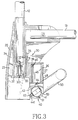
- the base (41) contains a first keyway (44) and a second keyway (441), each in communication with the cylindrical aperture (42) and extending along the entire length thereof. As seen in Fig. 3, the first keyway (44) is set at a position of 12 o'clock and the second keyway (441) is set at a position of 8 o'clock.
- the arcuate tube (50) has two straight ends (51) and an arcuate main portion extending integrally between the two straight ends (51). Each straight end (51) of the arcuate tube (50) is sized to be slidingly received in the cylindrical aperture (42) of the pivot (40).
- One of two springs (53) such as a V-shaped leaf spring as preferred in this embodiment, is secured within each of the straight ends (51) of the arcuate tube (50) and has a first protuberance (531) extending therefrom and sized to extend through and protrude from a hole (54) contained in the sidewall of the straight end (51).
- the first protuberance (531) is sized to be received in either the first keyway (44) or the second keyway (441) at one time.
- a second protuberance (52) protrudes from the outer periphery of the straight portion (51) of the arcuate tube (50) closer to the main arcuate portion and in line with the head of the first protuberance (531).
- Fig. 4 illustrates that in the embodiment of the invention, the arcuate tube (50) can be pivoted to support the whole playpen, e.g., the rocking cradle.
- the arcuate tube (50) placed in the right place the parents can readily rocker the playpen at ant time.
Landscapes
- Toys (AREA)
- Pinball Game Machines (AREA)
Abstract
Description
Claims (15)
- An improved playpen comprising:four bottom corner bracket; anda pair of rocker devices attached respectively to two opposed pairs of the bottom corner brackets.
- The playpen according to claim 1, characterized in that one of the rocker devices comprises:a pair of couplings;a pair of pivots each coupled to one of the couplings; andan arcuate tube received between a pair of pivots.
- The playpen according to claim 2, characterized in that the coupling comprises:a first socket; anda second socket integrally formed with the first socket adjacent thereto.
- The playpen according to claim 3, characterized in that a base of the first socket has formed thereon a rod which is upright and a bore extends through the rod.
- The playpen according to claim 3, characterized in that a long notch and a short notch are contained in a circumferential wall of the first socket respectively.
- The playpen according to claim 5, characterized in that the long notch is sized to engage with the web of the bottom corner bracket and a screw extends through the short notch.
- The playpen according to claim 3, characterized in that a slot is contained through a sidewall of the second socket and a ridge extends along an inner periphery of the second socket.
- The playpen according to claim 2, characterized in that the pivot comprises:a base; anda tubular top integrally formed with the base.
- The playpen according to claim 3, characterized in that the second socket is sized to receive a tubular top of the pivot.
- The playpen according to claim 8, characterized in that a groove is longitudinally contained down an outside periphery of the tubular top, an outward protruding tip being integrally formed on a resilient member of the tubular top and being dimensioned to extend through the slot of the second socket.
- The playpen according to claim 8, characterized in that a base of the pivot comprises a cylindrical aperture which extends in a direction perpendicular to the tubular top and contains two keyways each connecting to the cylindrical aperture.
- The playpen according to claim 2, characterized in that the arcuate tube comprises:two straight ends;an arcuate main portion extending integrally between the two straight ends; anda first protuberance and a second protuberance disposed on each said straight en of the arcuate tube.
- The playpen according to claim 12, characterized in that each of said straight ends is sized to be received in a respective cylindrical aperture of the pivot.
- The playpen according to claim 12, characterized in that the first protuberance is received in one of the keyways at one time and the second protuberance is in line with the first protuberance.
- The playpen according to claim 12, characterized in that a V-shaped leaf spring is secured within each of the straight ends of the arcuate tube by the first protuberance.
Applications Claiming Priority (2)
| Application Number | Priority Date | Filing Date | Title |
|---|---|---|---|
| US13925 | 1998-01-27 | ||
| US09/013,925 US5956786A (en) | 1998-01-27 | 1998-01-27 | Playpen |
Publications (2)
| Publication Number | Publication Date |
|---|---|
| EP0931488A2 true EP0931488A2 (en) | 1999-07-28 |
| EP0931488A3 EP0931488A3 (en) | 2000-03-22 |
Family
ID=21762546
Family Applications (1)
| Application Number | Title | Priority Date | Filing Date |
|---|---|---|---|
| EP98118822A Withdrawn EP0931488A3 (en) | 1998-01-27 | 1998-10-05 | Improved Playpen |
Country Status (2)
| Country | Link |
|---|---|
| US (1) | US5956786A (en) |
| EP (1) | EP0931488A3 (en) |
Cited By (4)
| Publication number | Priority date | Publication date | Assignee | Title |
|---|---|---|---|---|
| EP0995381A1 (en) * | 1998-10-22 | 2000-04-26 | Evenflo Company, Inc. | Playyard with rockers |
| EP1219212A1 (en) * | 2000-12-22 | 2002-07-03 | Kun Wang | Wobble device for a collapsible playpen |
| WO2008125459A1 (en) * | 2007-04-13 | 2008-10-23 | Baby Now, S.L. | Infant cot |
| PL424539A1 (en) * | 2018-02-08 | 2019-08-12 | Jerzy Stępiński | Dismountable and multifunctional cradle |
Families Citing this family (23)
| Publication number | Priority date | Publication date | Assignee | Title |
|---|---|---|---|---|
| US6158067A (en) * | 1999-06-25 | 2000-12-12 | Kenny Cheng | Convertible crib |
| US6341394B1 (en) * | 1999-09-29 | 2002-01-29 | Kun Wang | Sway device for a cradle |
| US20020114480A1 (en) * | 2001-02-20 | 2002-08-22 | Chen Er-Jui | Playpen having facility for coaxing infant |
| TW479490U (en) * | 2001-07-10 | 2002-03-11 | Kuen Wang | Structure of joint for game bed |
| US6450666B1 (en) * | 2001-09-06 | 2002-09-17 | Paris Briscoe | Kit for forming a support for a string of lights |
| DE20119260U1 (en) * | 2001-11-22 | 2002-04-04 | Cheng, Kenny, Taipeh/T'ai-pei | Removable support leg for a baby playpen |
| US6571408B1 (en) * | 2002-01-16 | 2003-06-03 | Kun Wang | Oscillatory device for a collapsible playpen |
| US6704949B2 (en) * | 2002-03-21 | 2004-03-16 | Simplicity, Inc. | Combination bassinet, changing table and bedside sleeper |
| US6854919B2 (en) * | 2002-06-20 | 2005-02-15 | S.C. Johnson & Son, Inc. | Push-lock handle assembly |
| US6721970B1 (en) * | 2002-10-08 | 2004-04-20 | Pao-Hsien Cheng | Foot of a baby bed |
| US20050005353A1 (en) * | 2003-05-29 | 2005-01-13 | Simplicity, Inc. | Bassinet selectively rockable when mounted upon a support as well as being displaced therefrom |
| US20070221598A1 (en) * | 2006-03-14 | 2007-09-27 | Azad Sabounjian | Connector for laundry rack |
| US11583103B2 (en) * | 2006-06-05 | 2023-02-21 | Richard Shane | Infant soothing device and method |
| US8782827B2 (en) | 2006-06-05 | 2014-07-22 | Richard Shane | Infant soothing device having an actuator |
| CN101496690B (en) * | 2008-01-29 | 2011-05-18 | 明门香港股份有限公司 | Baby cots and baby hammocks |
| US8079639B2 (en) * | 2008-05-16 | 2011-12-20 | Wonderland Nurserygoods Company Limited | Bouncer |
| USD688115S1 (en) * | 2011-09-12 | 2013-08-20 | Thorley Industries Llc | Corner assembly for a foldable child enclosure |
| US9351588B2 (en) | 2012-11-29 | 2016-05-31 | Kids Ii, Inc. | Child support unit for a play yard |
| US9675182B2 (en) * | 2013-08-05 | 2017-06-13 | Artsana Usa, Inc. | Bi-axially collapsible frame for a bassinet |
| CN104490172A (en) * | 2014-05-21 | 2015-04-08 | 浙江金华雪贝婴童用品制造有限公司 | Game bed bottom rocking mechanism |
| CN210300375U (en) | 2018-05-07 | 2020-04-14 | 明门(中国)幼童用品有限公司 | Foldable containing device |
| US11197560B2 (en) | 2018-05-07 | 2021-12-14 | Wonderland Switzerland Ag | Foldable bassinet |
| WO2025230859A1 (en) * | 2024-04-29 | 2025-11-06 | Baby Delight, Inc. | Portable crib with feet having receptacles for removably receiving structural components of the crib |
Family Cites Families (13)
| Publication number | Priority date | Publication date | Assignee | Title |
|---|---|---|---|---|
| US287721A (en) * | 1883-10-30 | William c | ||
| US744993A (en) * | 1903-08-22 | 1903-11-24 | John Barta | Cradle. |
| GB240268A (en) * | 1924-08-05 | 1925-10-01 | Frederick Charles Gear | Improvements in and relating to collapsible and convertible cots, ottomans and the like |
| US2389899A (en) * | 1943-05-31 | 1945-11-27 | Deddo Leonard | Building structure |
| US3338605A (en) * | 1964-10-05 | 1967-08-29 | Stoeber Alfred | Support structure |
| US3426367A (en) * | 1965-12-21 | 1969-02-11 | John G Bradford | Collapsible supporting structures |
| US3541618A (en) * | 1968-07-24 | 1970-11-24 | Grace Gutterman | Automatic crib rocker |
| US4247216A (en) * | 1979-08-22 | 1981-01-27 | Pansini Andrew L | Quick connect handle for swimming pool cleaning tools |
| US5271107A (en) * | 1992-10-09 | 1993-12-21 | Gof Sonia M | Infant bathing and crib device |
| US5387048A (en) * | 1993-08-03 | 1995-02-07 | Kuo; Cheng M. L. | Securing means for telescopic sticks of a multiple-fold umbrella |
| US5485655A (en) * | 1995-01-20 | 1996-01-23 | Wang; Kun | Hinge device for armrails of a playpen |
| US5590974A (en) * | 1995-05-30 | 1997-01-07 | Yang; Tian-Show | Assembling connector structure |
| US5779386A (en) * | 1996-08-15 | 1998-07-14 | Fisher-Price, Inc. | Apparatus and method for coupling support members |
-
1998
- 1998-01-27 US US09/013,925 patent/US5956786A/en not_active Expired - Fee Related
- 1998-10-05 EP EP98118822A patent/EP0931488A3/en not_active Withdrawn
Cited By (4)
| Publication number | Priority date | Publication date | Assignee | Title |
|---|---|---|---|---|
| EP0995381A1 (en) * | 1998-10-22 | 2000-04-26 | Evenflo Company, Inc. | Playyard with rockers |
| EP1219212A1 (en) * | 2000-12-22 | 2002-07-03 | Kun Wang | Wobble device for a collapsible playpen |
| WO2008125459A1 (en) * | 2007-04-13 | 2008-10-23 | Baby Now, S.L. | Infant cot |
| PL424539A1 (en) * | 2018-02-08 | 2019-08-12 | Jerzy Stępiński | Dismountable and multifunctional cradle |
Also Published As
| Publication number | Publication date |
|---|---|
| EP0931488A3 (en) | 2000-03-22 |
| US5956786A (en) | 1999-09-28 |
Similar Documents
| Publication | Publication Date | Title |
|---|---|---|
| EP0931488A2 (en) | Improved Playpen | |
| US6368006B1 (en) | Attachment mechanism for stroller tray accessory | |
| US4692953A (en) | Portable collapsible baby crib | |
| US4819285A (en) | Portable collapsible baby crib | |
| US5353451A (en) | Playpen frame structure | |
| US5454124A (en) | Foldable playyard with improved mechanism for collapsing the top rail structure | |
| US5781944A (en) | Foldable device for a crib | |
| US6102432A (en) | Direction changing device for a handle of a stroller | |
| US20070209112A1 (en) | Bassinet selectively rockable when mounted upon a support as well as being displaced therefrom | |
| US20010001162A1 (en) | Combination folding play pen with changing table and bassinet | |
| US5367725A (en) | Playpen structure | |
| ES3052087T3 (en) | Frame folding mechanism and crib frame | |
| US6874177B2 (en) | Baby furniture | |
| US6349434B1 (en) | Folding frame device for playpen | |
| KR20000029210A (en) | Playyard with rockers | |
| US6964634B2 (en) | Jumping device with convertible stabilizing base | |
| US4603828A (en) | Kinder bar and kinder grow | |
| US6065163A (en) | Foldable bed frame assembly | |
| GB2260570A (en) | Foldable joint for segments of a playpen structure | |
| CN209121686U (en) | A kind of baby rocking chair | |
| US6871912B1 (en) | Highchair | |
| EP0920825B1 (en) | A foldable bed detachably mounted onto a crib | |
| US20030122352A1 (en) | Device for mounting accessory wheels on stroller | |
| CN218528301U (en) | Folding structure | |
| TWI434662B (en) | Suspended baby crib |
Legal Events
| Date | Code | Title | Description |
|---|---|---|---|
| PUAI | Public reference made under article 153(3) epc to a published international application that has entered the european phase |
Free format text: ORIGINAL CODE: 0009012 |
|
| 17P | Request for examination filed |
Effective date: 19981005 |
|
| AK | Designated contracting states |
Kind code of ref document: A2 Designated state(s): AT BE CH DE DK ES FI FR GB GR IT LI NL PT SE |
|
| AX | Request for extension of the european patent |
Free format text: AL;LT;LV PAYMENT 19981005;MK;RO;SI |
|
| PUAL | Search report despatched |
Free format text: ORIGINAL CODE: 0009013 |
|
| AK | Designated contracting states |
Kind code of ref document: A3 Designated state(s): AT BE CH CY DE DK ES FI FR GB GR IE IT LI LU MC NL PT SE |
|
| AX | Request for extension of the european patent |
Free format text: AL;LT;LV PAYMENT 19981005;MK;RO;SI |
|
| AKX | Designation fees paid |
Free format text: AT BE CH DE DK ES FI FR GB GR IT LI NL PT SE |
|
| AXX | Extension fees paid |
Free format text: LV PAYMENT 19981005 |
|
| 17Q | First examination report despatched |
Effective date: 20011127 |
|
| STAA | Information on the status of an ep patent application or granted ep patent |
Free format text: STATUS: THE APPLICATION IS DEEMED TO BE WITHDRAWN |
|
| 18D | Application deemed to be withdrawn |
Effective date: 20020409 |