EP0931879A1 - Leitwand für Kraftfahrzeuge und Herstellungsverfahren - Google Patents
Leitwand für Kraftfahrzeuge und Herstellungsverfahren Download PDFInfo
- Publication number
- EP0931879A1 EP0931879A1 EP99400097A EP99400097A EP0931879A1 EP 0931879 A1 EP0931879 A1 EP 0931879A1 EP 99400097 A EP99400097 A EP 99400097A EP 99400097 A EP99400097 A EP 99400097A EP 0931879 A1 EP0931879 A1 EP 0931879A1
- Authority
- EP
- European Patent Office
- Prior art keywords
- forming
- recesses
- lateral
- recess
- sliding formwork
- Prior art date
- Legal status (The legal status is an assumption and is not a legal conclusion. Google has not performed a legal analysis and makes no representation as to the accuracy of the status listed.)
- Withdrawn
Links
- 238000000034 method Methods 0.000 title claims description 10
- 238000010276 construction Methods 0.000 title 1
- 230000004888 barrier function Effects 0.000 claims abstract description 22
- 238000009415 formwork Methods 0.000 claims description 34
- 230000001681 protective effect Effects 0.000 claims description 22
- 238000009749 continuous casting Methods 0.000 claims description 5
- 238000004519 manufacturing process Methods 0.000 claims description 4
- 239000011150 reinforced concrete Substances 0.000 claims description 4
- 230000002787 reinforcement Effects 0.000 claims description 4
- 238000009416 shuttering Methods 0.000 abstract 1
- 239000004567 concrete Substances 0.000 description 17
- 238000009434 installation Methods 0.000 description 9
- 238000005553 drilling Methods 0.000 description 4
- 230000015572 biosynthetic process Effects 0.000 description 3
- 239000000463 material Substances 0.000 description 3
- 229910052751 metal Inorganic materials 0.000 description 3
- 238000002955 isolation Methods 0.000 description 2
- 238000005259 measurement Methods 0.000 description 2
- 239000000203 mixture Substances 0.000 description 2
- 208000031968 Cadaver Diseases 0.000 description 1
- 239000004793 Polystyrene Substances 0.000 description 1
- 241001080024 Telles Species 0.000 description 1
- 230000000712 assembly Effects 0.000 description 1
- 238000000429 assembly Methods 0.000 description 1
- 238000009412 basement excavation Methods 0.000 description 1
- 238000005266 casting Methods 0.000 description 1
- 239000004568 cement Substances 0.000 description 1
- 230000000295 complement effect Effects 0.000 description 1
- 239000000470 constituent Substances 0.000 description 1
- 239000004794 expanded polystyrene Substances 0.000 description 1
- 230000009931 harmful effect Effects 0.000 description 1
- 229920002223 polystyrene Polymers 0.000 description 1
- 238000007789 sealing Methods 0.000 description 1
- 238000000926 separation method Methods 0.000 description 1
- 239000002689 soil Substances 0.000 description 1
Images


Classifications
-
- E—FIXED CONSTRUCTIONS
- E01—CONSTRUCTION OF ROADS, RAILWAYS, OR BRIDGES
- E01F—ADDITIONAL WORK, SUCH AS EQUIPPING ROADS OR THE CONSTRUCTION OF PLATFORMS, HELICOPTER LANDING STAGES, SIGNS, SNOW FENCES, OR THE LIKE
- E01F15/00—Safety arrangements for slowing, redirecting or stopping errant vehicles, e.g. guard posts or bollards; Arrangements for reducing damage to roadside structures due to vehicular impact
- E01F15/02—Continuous barriers extending along roads or between traffic lanes
- E01F15/04—Continuous barriers extending along roads or between traffic lanes essentially made of longitudinal beams or rigid strips supported above ground at spaced points
- E01F15/0476—Foundations
-
- E—FIXED CONSTRUCTIONS
- E01—CONSTRUCTION OF ROADS, RAILWAYS, OR BRIDGES
- E01F—ADDITIONAL WORK, SUCH AS EQUIPPING ROADS OR THE CONSTRUCTION OF PLATFORMS, HELICOPTER LANDING STAGES, SIGNS, SNOW FENCES, OR THE LIKE
- E01F8/00—Arrangements for absorbing or reflecting air-transmitted noise from road or railway traffic
- E01F8/0005—Arrangements for absorbing or reflecting air-transmitted noise from road or railway traffic used in a wall type arrangement
- E01F8/0023—Details, e.g. foundations
-
- E—FIXED CONSTRUCTIONS
- E01—CONSTRUCTION OF ROADS, RAILWAYS, OR BRIDGES
- E01F—ADDITIONAL WORK, SUCH AS EQUIPPING ROADS OR THE CONSTRUCTION OF PLATFORMS, HELICOPTER LANDING STAGES, SIGNS, SNOW FENCES, OR THE LIKE
- E01F8/00—Arrangements for absorbing or reflecting air-transmitted noise from road or railway traffic
- E01F8/02—Arrangements for absorbing or reflecting air-transmitted noise from road or railway traffic specially adapted for sustaining vegetation or for accommodating plants ; Embankment-type or crib-type noise barriers; Retaining walls specially adapted to absorb or reflect noise
- E01F8/027—Arrangements for absorbing or reflecting air-transmitted noise from road or railway traffic specially adapted for sustaining vegetation or for accommodating plants ; Embankment-type or crib-type noise barriers; Retaining walls specially adapted to absorb or reflect noise with external support, e.g. wall facing
- E01F8/028—Through-type, e.g. between adjacent kerbs
Definitions
- the invention relates to a road protection device placed on at least one of the edges of a traffic lane, as well as a process for producing such a protection device.
- safety barriers can be used to limit traffic lanes and thereby protect pedestrians or buildings, especially angles of building, on airfields, parking lots and places similar.
- Safety barriers can be built of metallic elements or be made of concrete.
- the protective screens are placed fairly close to the edges of traffic lanes, which implies that they must be protected by security barriers.
- FR-2.508.511 which describes a taxiway edge device intended for combine the function of a safety barrier and that of a wall foundation.
- This device includes a base in a single part formed by a part constituting a safety separator and of a part forming the support of a noise barrier.
- the screen is fixed on the support by a fixing plate.
- the support can be formed so as to delimit a planting tank.
- the document FR-2,704,880 describes a device for road protection including a lower part forming a base concrete constituting a safety barrier, and part sound-insulating upper constituting a noise barrier.
- the noise barrier is fixed to the base by a plate.
- the object of the invention is to remedy the drawbacks described above.
- the invention must propose a solution which allows simpler installation and therefore faster and less expensive a set of a protective screen and a security barrier.
- the solution that the invention proposes must be used of the sliding formwork technique.
- the object of the invention is achieved by a protection device road provided on at least one of the edges of a lane circulation.
- This protection device includes a lower part forming a base, an upper part constituting a screen protection and a side part forming a safety barrier. The upper part and side part create volume between them free.
- the device of the invention includes in the lower part at least one recess open towards the top and intended to cooperate with the upper part in fixing the latter on the lower part.
- the recess (s) are spaced from the side.
- the side part forming a safety barrier can be made up of prefabricated concrete juxtaposed modular elements or metallic elements or, more advantageously, be continuously cast on site.
- the device of the invention according to which the lower part of the protection device is provided with recesses intended to receive at least in part, elements of the upper part constituting a protective screen, allows to avoid the use of elements fixing aids such as plates or core anchors.
- the two forms of the sliding formwork machine and which correspond respectively to the lower part and to the part side of the device of the invention can be arranged one beside on the other or be shifted in the direction of advancement of the machine depending on the nature of the concrete used.
- the layout of the formwork in this case also depends on the possible use of a separation means intended to prevent the concrete forming the part side blends with that of the lower part.
- the lower part serves as a base for the both for the upper part and for the lateral part.
- the object of the invention is achieved by a method of production a road protection device on at least one of the edges a traffic lane, the device comprising a part lower forming a base, an upper part constituting a protective screen and a side part forming a barrier security.
- the realization of the side part with the lower part includes several variations.
- the lateral part and the lower part is made in a single block by means of a single formwork.
- the lateral part and the lower part are made distinctly by a sliding formwork double body.
- the concrete introduction troughs in each of the bodies of the formwork or in the two bodies of the formwork are offset from each other by a distance such that the concrete at the bottom has set enough for the concrete of the side part does not mix, during its casting, with that from the bottom.
- the application of a separating product between the two concrete parts can be expected.
- the invention makes it possible to mount the screen of protection, and if necessary also, a lateral part in elements metallic, without auxiliary elements such as fixing plates, or cored anchors.
- the invention thus facilitates installation, in particular the adjustment of the positioning of the posts and the constituent panels the protection screen.
- Another advantage of the invention consists in the possibility of realize the device of the invention by following the edge profile of the taxiway or other positioning line of the protective device, without having to carry out measurement steps and determining drilling or drilling points for fixing posts.
- the invention is also advantageous in the case where the route traffic involves the creation of steps.
- the lower part includes a trapezoidal part.
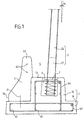
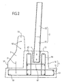
- the device of the invention shown in Figures 1 and 2 comprises a lower part 1 formed by a wide base 11 and a body 12, an upper part 2 constituting a protective screen, as well as a side part 3 forming a security barrier.
- the body 12 of the lower part 1 has an upper surface 13 in which recesses 4 open up are made.
- the recesses 4 are intended to cooperate with the upper part 2 when fixing it to the lower part 1.
- the recesses 4 are formed so as to receive poles of supports 21 between which are held panels 22 forming the protection screen.
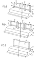
- the recesses 4 can also be formed so as to receive the lower edge of a panel 23 as this is shown in Figure 5.
- the different shapes of recesses are shown in Figures 3 to 5 and referenced 41 and 42, as explained below.
- the recesses 4 are arranged in the body 12 of the part lower 1 so that they are spaced at a time from the part sideways and from each other in the lengthwise direction of the part lower 1.
- the upper part 2 and the part lateral 3 provide a free space between them 5.
- the free volume 5 has a sufficient width for, for example example, allow a person to move along the screen of protection 2 or to be able to be filled at least partially with of soil and to place plants there.
- the lower part 1 is advantageously made of concrete armed with a frame 6.
- Figures 1 and 2 show a mode of embodiment according to which the lower 1 and lateral 3 parts are formed individually, the lateral part 3 being anchored in the lower part 1 by means of rods 31.
- Figure 6 shows a mode according to which the lower 1 and lateral 3 parts are formed in one piece.
- the frame 6 consists, according to one or the other of the embodiments or of its chosen variants, in combinations of rods 61 or 62 arranged according to the extent longitudinal of the lower part 1 and the lateral part 3 and of cage reinforcements 63 to 68 whose geometry and dimensions are adapted to those of the corresponding part of the the invention.
- the device shown in Figure 1 includes a plurality of rods 61 oriented along the longitudinal extent of the lower part 1 as well as two cage frames 63 and 64, the shapes are adapted respectively to that of the wide base 11 and of the body 12.
- the cages 63 and 64 interpenetrate and are fixed one compared to each other.
- the frame of the lower part 1 comprises, in addition to a cage frame 63 for the wide base 11, cage frames 65 and 66 whose shapes and dimensions are chosen so as to arm the body 12 in two parts of its width omitting a part of the body 12 where there are recesses 4.
- the frames 65 and 66 are arranged approximately perpendicular to the cage 63 and connected by pins 67.
- the armature shown in the Figure 1 is more suitable for making lower parts whose recesses are formed to receive posts 21, the reinforcement shown in Figure 2 is more suitable for realizations of lower parts provided with elongated recesses.
- the device of the invention is shown in Figures 1 and 2 with a lateral part 3 whose frame is constituted by rods 62 arranged in the longitudinal direction of the lateral part 3.
- this embodiment including the side part 3 corresponds to a reinforced concrete slide (GBA) usually used at roadside or on median can include any type of frame used to date in GBA usually used.
- the rods 31 represent schematically the different attachments that can be used to fix the GBA on the ground or at the edge of roadways or a work of art.
- the frame 6 comprises, in addition to the rods longitudinal 61 and 62 of cage frames 63 and 64 corresponding to the embodiment of Figure 1 or cage frames 63, 65 and 66 corresponding to the embodiment of Figure 2, a cage frame 68.
- the cage 68 is formed of so as to match the shape of the bottom of the part side 3 which will be formed in one piece with the lower part 1, and is attached at the same time to cages 63 and 64.
- Figures 3 to 5 show different shapes and arrangements recesses used by the invention.
- Figure 3 shows a arrangement according to which the recesses referenced 41 have a shape rectangular with a square cross section arranged one after the other in the longitudinal direction of the lower part 1.
- Each recess 41 is intended to receive a support post 21.
- the posts 21 can be provided at the lower end with a hoop 7.
- Each pair of neighboring posts receives a panel 22 and the maintains in a vertical position shown in Figure 3 or in a slightly tilted position at an angle a to the vertical as shown in Figures 1, 2 and 6.
- the shape and dimensions of the recesses 41, and in particular the shape of their cross sections depend on the dimensions and the shape of the posts to be put in place.
- the sections transverse of the recesses 41 may for example be square, rectangular or circular.
- the recesses 41 can be aligned with each other along a line essentially parallel to an edge of the lower part 1.
- the recesses 41 can also be arranged according to two or more alignments depending on the structure you want give to the protective screen. So the arrangement of the recesses 41 shown in Figure 3 corresponds to a protective screen to continuous surface, while the arrangement of the recesses 41 shown in Figure 4 corresponds to an interrupted structure of the surface of the protective screen.
- Figure 5 shows an embodiment in which the part lower 1 is provided with a single elongated recess 42, having the shaped like a groove and extending substantially in the direction of the length of the lower part 1.
- This type of recess is chosen advantageously for applications where it is preferred to insert panels 23 constituting the protective screen, directly by their lower edge in the lower part 1 of the device of the invention.
- the protective screen thus formed may or may not include support posts.
- the recesses 41 and 42 allow by the variation of their dimensions and their arrangement, of which Figures 3 to 5 only show as some examples, to mount and fix panels forming a protective screen with different tilt angles a. So a same protective screen can present over a given distance panels whose angle of inclination changes periodically or aperiodically regardless of the importance of the variation.
- the fact of being able fix the panels forming the protective screen, without or with posts, without the use of auxiliary elements such as fixing plates or cored anchors provides the advantage particular to be able to place the panels and / or posts in the recesses formed and provided for this purpose and to be able to tilt them and orient one with respect to the other.
- a sliding formwork machine comprising one or two partial forms depending on whether you want to obtain the part bottom and side part individually or in one piece.
- the frame 6 is first placed such that this is shown in Figure 7.
- elements in one light material such as polystyrene blocks, where correspond to the recesses in the lower part to be produced.
- the slipform machine includes mobile elements resistant or made resistant to different characteristics of concrete, especially its humidity. Such moving elements would then be repeatedly introduced to the places provided for formed recesses in the frame as and when advancement of the sliding formwork machine and removed from the part lower thus produced by the sliding formwork machine as and measure of its progress.
- Such movable elements could be Introduced by the sliding formwork machine into a section of freshly poured concrete that has not yet set, like a piston, thereby driving out a portion of the corresponding concrete.
- the sliding formwork can be formed in its upper part appropriately.
- the process of the invention makes it possible to produce the protection device according to the invention in reinforced concrete by making a single pass of a sliding formwork machine.
Landscapes
- Engineering & Computer Science (AREA)
- Architecture (AREA)
- Civil Engineering (AREA)
- Structural Engineering (AREA)
- Life Sciences & Earth Sciences (AREA)
- Sustainable Development (AREA)
- Road Paving Structures (AREA)
- Forms Removed On Construction Sites Or Auxiliary Members Thereof (AREA)
Applications Claiming Priority (2)
| Application Number | Priority Date | Filing Date | Title |
|---|---|---|---|
| FR9800739 | 1998-01-23 | ||
| FR9800739A FR2774106A1 (fr) | 1998-01-23 | 1998-01-23 | Dispositif de protection routiere et procede de realisation d'un tel dispositif |
Publications (1)
| Publication Number | Publication Date |
|---|---|
| EP0931879A1 true EP0931879A1 (de) | 1999-07-28 |
Family
ID=9522108
Family Applications (1)
| Application Number | Title | Priority Date | Filing Date |
|---|---|---|---|
| EP99400097A Withdrawn EP0931879A1 (de) | 1998-01-23 | 1999-01-15 | Leitwand für Kraftfahrzeuge und Herstellungsverfahren |
Country Status (3)
| Country | Link |
|---|---|
| EP (1) | EP0931879A1 (de) |
| CA (1) | CA2259874A1 (de) |
| FR (1) | FR2774106A1 (de) |
Cited By (6)
| Publication number | Priority date | Publication date | Assignee | Title |
|---|---|---|---|---|
| DE102005025049B3 (de) * | 2005-05-30 | 2006-10-05 | Herhof Straßen-und Tiefbau GmbH | Verfahren zur Herstellung einer Fundamentbefestigung für Pfosten von Schutzplanken und Fundamentbefestigung |
| EP2278072A2 (de) * | 2009-07-21 | 2011-01-26 | asa-protect Entwicklungs GmbH | Schutzvorrichtung |
| AT509872B1 (de) * | 2010-05-06 | 2011-12-15 | Redlberger Alfred | Rückhaltesystem für fahrzeuge im bereich von strassen |
| GB2520843A (en) * | 2013-10-28 | 2015-06-03 | Mark Anthony Hales | Improvements in or relating to supporting temporary fence panels |
| CN107119601A (zh) * | 2017-06-28 | 2017-09-01 | 多吉泽仁 | 一种山路防护栏杆 |
| IT201600102336A1 (it) * | 2016-10-12 | 2018-04-12 | Paver S P A | Elemento di fondazione per una barriera, barriera provvista di detto elemento di fondazione e relativo procedimento di costruzione |
Citations (8)
| Publication number | Priority date | Publication date | Assignee | Title |
|---|---|---|---|---|
| FR2457928A1 (fr) * | 1979-06-01 | 1980-12-26 | Salviam Brun | Dispositif formant glissiere de securite et support de panneaux |
| DE8109198U1 (de) * | 1981-09-03 | Technische Sicherheits-Systeme GmbH, 4000 Düsseldorf | "Tragkonstruktion für Lärmschutzwände" | |
| FR2508511A1 (fr) | 1981-06-25 | 1982-12-31 | Tech Special Securite | Dispositif de bordure de voie de circulation, notamment de bordure d'autoroute |
| DE3423566A1 (de) * | 1984-06-27 | 1986-01-09 | EVERGREEN GmbH Bepflanzte Stütz- und Lärmschutzwände, 7100 Heilbronn | Laermschutzschirm |
| AT393146B (de) * | 1989-04-14 | 1991-08-26 | Universale Bau Aktiengesellsch | Betonsockel zur herstellung einer aus aneinandergereihten, mit ihren stirnflaechen aneinanderliegenden betonsockeln gefertigten leiteinrichtung |
| FR2698112A1 (fr) * | 1992-11-17 | 1994-05-20 | Gros Sa Ets | Procédé d'ancrage d'un écran acoustique, moyens en vue de la mise en Óoeuvre du procédé et écrans acoustiques et glissières de sécurité obtenus par le dit procédé. |
| FR2704880A1 (fr) | 1993-05-07 | 1994-11-10 | Colas Sa | Dispositif de protection routière polyvalent. |
| FR2720765A1 (fr) * | 1994-06-02 | 1995-12-08 | Ind Entreprise | Dispositif de fixation d'un écran anti-bruit sur une glissière de sécurité d'une voie de circulation. |
-
1998
- 1998-01-23 FR FR9800739A patent/FR2774106A1/fr not_active Withdrawn
-
1999
- 1999-01-15 EP EP99400097A patent/EP0931879A1/de not_active Withdrawn
- 1999-01-22 CA CA 2259874 patent/CA2259874A1/en not_active Abandoned
Patent Citations (8)
| Publication number | Priority date | Publication date | Assignee | Title |
|---|---|---|---|---|
| DE8109198U1 (de) * | 1981-09-03 | Technische Sicherheits-Systeme GmbH, 4000 Düsseldorf | "Tragkonstruktion für Lärmschutzwände" | |
| FR2457928A1 (fr) * | 1979-06-01 | 1980-12-26 | Salviam Brun | Dispositif formant glissiere de securite et support de panneaux |
| FR2508511A1 (fr) | 1981-06-25 | 1982-12-31 | Tech Special Securite | Dispositif de bordure de voie de circulation, notamment de bordure d'autoroute |
| DE3423566A1 (de) * | 1984-06-27 | 1986-01-09 | EVERGREEN GmbH Bepflanzte Stütz- und Lärmschutzwände, 7100 Heilbronn | Laermschutzschirm |
| AT393146B (de) * | 1989-04-14 | 1991-08-26 | Universale Bau Aktiengesellsch | Betonsockel zur herstellung einer aus aneinandergereihten, mit ihren stirnflaechen aneinanderliegenden betonsockeln gefertigten leiteinrichtung |
| FR2698112A1 (fr) * | 1992-11-17 | 1994-05-20 | Gros Sa Ets | Procédé d'ancrage d'un écran acoustique, moyens en vue de la mise en Óoeuvre du procédé et écrans acoustiques et glissières de sécurité obtenus par le dit procédé. |
| FR2704880A1 (fr) | 1993-05-07 | 1994-11-10 | Colas Sa | Dispositif de protection routière polyvalent. |
| FR2720765A1 (fr) * | 1994-06-02 | 1995-12-08 | Ind Entreprise | Dispositif de fixation d'un écran anti-bruit sur une glissière de sécurité d'une voie de circulation. |
Cited By (7)
| Publication number | Priority date | Publication date | Assignee | Title |
|---|---|---|---|---|
| DE102005025049B3 (de) * | 2005-05-30 | 2006-10-05 | Herhof Straßen-und Tiefbau GmbH | Verfahren zur Herstellung einer Fundamentbefestigung für Pfosten von Schutzplanken und Fundamentbefestigung |
| EP2278072A2 (de) * | 2009-07-21 | 2011-01-26 | asa-protect Entwicklungs GmbH | Schutzvorrichtung |
| AT509872B1 (de) * | 2010-05-06 | 2011-12-15 | Redlberger Alfred | Rückhaltesystem für fahrzeuge im bereich von strassen |
| AT509872A4 (de) * | 2010-05-06 | 2011-12-15 | Redlberger Alfred | Rückhaltesystem für fahrzeuge im bereich von strassen |
| GB2520843A (en) * | 2013-10-28 | 2015-06-03 | Mark Anthony Hales | Improvements in or relating to supporting temporary fence panels |
| IT201600102336A1 (it) * | 2016-10-12 | 2018-04-12 | Paver S P A | Elemento di fondazione per una barriera, barriera provvista di detto elemento di fondazione e relativo procedimento di costruzione |
| CN107119601A (zh) * | 2017-06-28 | 2017-09-01 | 多吉泽仁 | 一种山路防护栏杆 |
Also Published As
| Publication number | Publication date |
|---|---|
| FR2774106A1 (fr) | 1999-07-30 |
| CA2259874A1 (en) | 1999-07-23 |
Similar Documents
| Publication | Publication Date | Title |
|---|---|---|
| EP0463925B1 (de) | Verfahren zur Herstellung eines halbunterirdischen Bauwerks an einem Bergabhang und auf diese Weise hergestelltes Bauwerk | |
| EP0489054B1 (de) | Zellulare strukturen zum stützen von wänden | |
| WO1986002967A1 (fr) | Systeme de construction modulaire d'une structure couverte | |
| FR2774106A1 (fr) | Dispositif de protection routiere et procede de realisation d'un tel dispositif | |
| BE1007984A5 (fr) | Dispositif de protection routiere polyvalent. | |
| EP0197021B1 (de) | Verfahren zum Bauen eines Tunnels | |
| FR2818998A1 (fr) | Procede pour la realisation d'ouvrages de genie civil, et notamment de piscines ou bassins de retenue d'eau, et moyens pour sa mise en oeuvre | |
| EP1258565A1 (de) | Vorgefertigtes Brückenlager | |
| FR2903437A1 (fr) | Element prefabrique pour la realisation d'une paroi en beton arme et paroi ainsi realisee | |
| BE1001360A3 (fr) | Pont semi-prefabrique. | |
| EP0242497B1 (de) | Tunnelbauverfahren | |
| FR2727447A1 (fr) | Ouvrage de passage sous remblai et son procede de realisation | |
| EP0424223A1 (de) | Verfahren zum schnellen Herstellen von zwei übereinander liegenden Strassen mit einem auf der bestehenden Strasse verlegten Bauwerk, ohne den Verkehr zu behindern | |
| EP2148019A2 (de) | Blockbaustein für Mauern | |
| EP2231947B1 (de) | Vorgefertigtes element zur herstellung einer stahlbetonplatte und so hergestellte platte | |
| FR2699200A1 (fr) | Dalle de hourdis préfabriquée et procédé de réalisation d'un pont utilisant de telles dalles. | |
| FR2637626A1 (fr) | Ecran anti-bruit vegetalisable | |
| FR2580011A1 (en) | Method for building the foundations of a construction, formwork intended for the implementation of this method, and construction thus obtained | |
| FR2558868A1 (fr) | Procede de construction de parois de batiments ou autres murs, et element de coffrage pour sa mise en oeuvre | |
| FR2629496A1 (fr) | Murs de soutenement du type mur-caisson en elements en beton prefabriques | |
| EP3115509B1 (de) | Verfahren zur herstellung und aufstellung eines bauwerks | |
| FR2938856A1 (fr) | Chapiteau prefabrique en beton, et procede de mise en oeuvre d'un tel chapiteau dans une ossature de plancher | |
| NL1014818C2 (nl) | Dekconstructie. | |
| FR2634236A1 (fr) | Procede pour reparer une fondation comportant des tetes de pieux deteriorees, notamment de pieux en bois | |
| FR2836492A1 (fr) | Mur antibruit realise avec des elements prefabriques a la presse, en materiaux fibreux tel que par exemple le beton de bois et par du beton coule en oeuvre eventuellement a la pompe |
Legal Events
| Date | Code | Title | Description |
|---|---|---|---|
| PUAI | Public reference made under article 153(3) epc to a published international application that has entered the european phase |
Free format text: ORIGINAL CODE: 0009012 |
|
| AK | Designated contracting states |
Kind code of ref document: A1 Designated state(s): AT BE CH DE DK ES FI FR GB IE IT LI LU MC NL SE |
|
| AX | Request for extension of the european patent |
Free format text: AL;LT;LV;MK;RO;SI |
|
| 17P | Request for examination filed |
Effective date: 20000128 |
|
| AKX | Designation fees paid |
Free format text: AT BE CH DE DK ES FI FR GB IE IT LI LU MC NL SE |
|
| 17Q | First examination report despatched |
Effective date: 20030217 |
|
| RTI1 | Title (correction) |
Free format text: GUARDRAIL SYSTEM AND METHOD OF CONSTRUCTION |
|
| STAA | Information on the status of an ep patent application or granted ep patent |
Free format text: STATUS: THE APPLICATION IS DEEMED TO BE WITHDRAWN |
|
| 18D | Application deemed to be withdrawn |
Effective date: 20030628 |