EP0931907A2 - Bohrlochperforator und Verfahren zu dessen Herstellung - Google Patents
Bohrlochperforator und Verfahren zu dessen Herstellung Download PDFInfo
- Publication number
- EP0931907A2 EP0931907A2 EP99300214A EP99300214A EP0931907A2 EP 0931907 A2 EP0931907 A2 EP 0931907A2 EP 99300214 A EP99300214 A EP 99300214A EP 99300214 A EP99300214 A EP 99300214A EP 0931907 A2 EP0931907 A2 EP 0931907A2
- Authority
- EP
- European Patent Office
- Prior art keywords
- perforating gun
- pressure test
- section
- module
- pressure
- Prior art date
- Legal status (The legal status is an assumption and is not a legal conclusion. Google has not performed a legal analysis and makes no representation as to the accuracy of the status listed.)
- Withdrawn
Links
- 238000000034 method Methods 0.000 title claims abstract description 26
- 238000012360 testing method Methods 0.000 claims abstract description 165
- 238000003780 insertion Methods 0.000 claims abstract description 12
- 230000037431 insertion Effects 0.000 claims abstract description 12
- 125000006850 spacer group Chemical group 0.000 claims description 71
- 238000010304 firing Methods 0.000 claims description 23
- 238000005474 detonation Methods 0.000 claims description 18
- 239000002360 explosive Substances 0.000 description 29
- 238000012546 transfer Methods 0.000 description 26
- 230000000712 assembly Effects 0.000 description 7
- 238000000429 assembly Methods 0.000 description 7
- 230000000295 complement effect Effects 0.000 description 5
- 239000012530 fluid Substances 0.000 description 5
- 229910000831 Steel Inorganic materials 0.000 description 2
- 239000003999 initiator Substances 0.000 description 2
- 239000010959 steel Substances 0.000 description 2
- 230000004888 barrier function Effects 0.000 description 1
- 238000010276 construction Methods 0.000 description 1
- 238000013461 design Methods 0.000 description 1
- 239000007788 liquid Substances 0.000 description 1
- 239000000463 material Substances 0.000 description 1
- 239000000843 powder Substances 0.000 description 1
- 238000007789 sealing Methods 0.000 description 1
- 239000011800 void material Substances 0.000 description 1
Images


Classifications
-
- E—FIXED CONSTRUCTIONS
- E21—EARTH OR ROCK DRILLING; MINING
- E21B—EARTH OR ROCK DRILLING; OBTAINING OIL, GAS, WATER, SOLUBLE OR MELTABLE MATERIALS OR A SLURRY OF MINERALS FROM WELLS
- E21B43/00—Methods or apparatus for obtaining oil, gas, water, soluble or meltable materials or a slurry of minerals from wells
- E21B43/11—Perforators; Permeators
- E21B43/116—Gun or shaped-charge perforators
- E21B43/117—Shaped-charge perforators
Definitions
- This invention relates to a perforating gun and to a method for preparation thereof. More particularly, the invention relates to a method and apparatus for creating leak-tested perforating gun assemblies
- a perforating gun assembly During the process of perforating an oil or gas well, a perforating gun assembly has to be lowered into and positioned properly in the wellbore. Quite often, the gun assembly will have to spend some time prior to firing in a fluid-filled environment in the wellbore. If the gun system develops a leak which allows wellbore fluids to enter the gun system, several things could happen which are not desirable. The system could misfire altogether, only partially fire, fire low order and thereby damaging downhole equipment or becoming stuck, and so on. Therefore, it is important that a gun system have no leaks.
- a typical perforating gun assembly consists of one or more perforating guns, as well as possibly comprising some spacer sections. If the zone to be perforated is longer than the amount which could be perforated with a single gun, then multiple perforating guns are connected together to create a perforating gun assembly of the desired length. Further, if there is more than one zone is to be perforated, and there is some distance between the zones to be perforated, spacer sections are inserted between the guns in the gun assembly. These spacer sections have detonation cord running from end to end, to transfer the ignition through the spacer section to the next component.
- an explosive transfer system is employed. This could be an overlap of detonating cord, the use of boosters either overlapped or end to end, or other known methods.
- connection point between the guns When perforating guns are coupled together to run into the wellbore, this connection point between the guns would then be untested. If testing of this connection point is desired, the only option is to test at the well site, which is highly undesirable. The untested connections poise a much higher leak risk than the tested connections.
- the apparatus consists of perforating gun "modules", each module consisting of a pressure test connector connected to each end of a perforating gun section (the perforating gun section consisting of one or more perforating guns connected together), whereby when each of the pressure test connectors is operably attached to each end of a perforating gun section, the pressure test connectors are capable of holding sufficient pressure to pressure test their respective perforating gun section. Once the pressure test connectors are attached, the perforating gun module is pressure tested. After the perforating module is tested, the pressure test connections are not removed.
- the gun assembly is constructed at the well site by connecting several previously tested perforating gun modules together, by operably connecting one of the pressure test connectors on a first perforating gun module to a pressure test connector on a second perforating gun module. As many additional perforating gun modules can be added to the gun assembly as desired.
- spacer modules may also be prepared in a manner similar to that used to prepare the perforating gun modules, and the spacer modules pressure tested.
- the prepared and tested spacer modules may also be included as components in the gun assembly.
- An explosive transfer assembly is used to transfer the detonation signal from one module to the next.
- the pressure test connectors will allow the gun system to be fired in both directions (bottom-up or top-down) at the desired time by incorporating a bi-directional explosive transfer system.
- a benefit of such a feature is that if a gun does fire low order for any reason, the low order will likely be confined to one module, as the explosive transfer between guns is designed to fail in a low order situation and therefore stop the firing train.
- the firing system may also use a pressure test connector similar to those used in the gun modules and be tested prior to deployment.
- the firing system may be connected directly to the guns or deployed later.
- a method for preparing a perforating gun assembly for insertion into and use in a wellbore comprising at least a first and a second perforating gun module, each of the modules having a first and a second end
- the method comprising: creating each perforating gun module by taking a perforating gun section that has a first and a second end, and operably attaching a first pressure test connector to the first end of the perforating gun section and operably attaching a second pressure test connector to the second end of the perforating gun section, whereby when the pressure test connectors are operably attached to each end of the perforating gun section, the pressure test connectors are capable of holding sufficient pressure for pressure testing of the complete perforating gun module; pressure testing each of the perforating gun modules; and connecting the perforating gun modules together by operably connecting one of the pressure test connectors on the first perforating gun module to one of the pressure test connector on the second perforating gun module.
- the gun assembly further comprises a firing system.
- the firing system may be added to the gun assembly after the gun assembly is already lowered into position for firing in the wellbore; or the firing system is added to the gun assembly as it is being prepared for insertion into the wellbore.
- the gun assembly further comprises at least one spacer module
- the method further comprises: creating the or each spacer module by taking a spacer section having a first and a second end, and operably attaching a first pressure test connector to a first end of the spacer section and a second pressure test connector to the second end of the spacer section, whereby when the pressure test connectors are operably attached to each end of the spacer section, the pressure test connectors are capable of holding sufficient pressure for pressure testing of the complete spacer module; pressure testing the at least one spacer module; and connecting the spacer module together with the perforating gun modules by operably connecting one of the pressure test connectors on the first perforating gun module to one of the pressure test connectors on the spacer portion, and operably connecting one of the pressure test connectors on the second perforating gun module to the second pressure test connector on the spacer module.
- the step of creating the perforating gun modules further comprises inserting tandem connectors between each of the pressure test connectors and their respective perforating gun section, each tandem section comprising detonation cord and a firing device.
- the perforating gun modules further comprise an explosive transfer assembly.
- the tandem connectors further comprise explosive transfer assemblies.
- the step of operably connecting the modules together is accomplished by threaded connections or by a swivel joint.
- a method for preparing a perforating gun module for insertion into and use in a wellbore comprising: creating a perforating gun module by taking a perforating gun section that has a first and a second end, and operably attaching a first pressure test connector to the first end of the perforating gun section and operably attaching a second pressure test connector to the second end of the perforating gun section, whereby when the pressure test connectors are operably attached to each end of the perforating gun section, the pressure test connectors are capable of holding sufficient pressure for pressure testing of the complete perforating gun module; pressure testing the perforating gun module; inserting and using the perforating gun module in the well bore without removing the pressure test connectors.
- the step of creating the perforating gun modules further comprises inserting tandem connectors between each of the pressure test connectors and the perforating gun section, each tandem section comprising detonation cord and a firing device.
- the perforating gun module further comprise an explosive transfer assembly.
- the tandem connectors further comprise explosive transfer assemblies.
- a method for preparing a spacer module for insertion into and use in a wellbore comprising: creating the spacer module by taking a spacer section that has a first and a second end, and operably attaching a first pressure test connector to the first end of the spacer section and operably attaching a second pressure test connector to the second end of the spacer section, whereby when the pressure test connectors are operably attached to each end of the spacer section, the pressure test connectors are capable of holding sufficient pressure for pressure testing of the complete spacer module; pressure testing the spacer module; inserting and using the spacer module in the well bore without removing the pressure test connectors.
- the step of creating the spacer modules further comprises inserting tandem connectors between each of the pressure test connectors and the perforating gun section, each tandem section comprising detonation cord and a firing device.
- the spacer module further comprise an explosive transfer assembly.
- the tandem connectors further comprise explosive transfer assemblies.
- perforating gun assembly for use in an oil or gas well, comprising: at least a first and a second perforating gun module, each of the modules having a first and a second end, each perforating gun module comprising a perforating gun section that has a first and a second end, a first pressure test connector operably connected to the first end of the perforating gun section and a second pressure test connector operably attached to the second end of the perforating gun section, whereby when the pressure test connectors are operably attached to each end of the perforating gun section, the pressure test connectors are capable of holding sufficient pressure for pressure testing of the complete perforating gun module; and wherein the at least two perforating gun modules are operably connected.
- the perforating gun assembly further comprising a firing system.
- the gun assembly further comprises: at least one spacer module, the at least one spacer module comprising a spacer section having a first and a second end, a first pressure test connector operably attached to a first end of the spacer section and a second pressure test connector operably attached to the second end of the spacer section, whereby when the pressure test connectors are operably attached to each end of the spacer section, the pressure test connectors are capable of holding sufficient pressure for pressure testing of the complete spacer module; and wherein the spacer module is connected to the perforating gun modules by operably connecting one of the pressure test connectors on the first perforating gun module to one of the pressure test connectors on the spacer portion, and operably connecting one of the pressure test connectors on the second perforating gun module to the second pressure test connector on the spacer module.
- the perforating gun assembly further comprises tandem connectors, the tandem connectors being operably connected between each of the pressure test connectors and their respective perforating gun section, each tandem connector comprising detonation cord and a firing device.
- the perforating gun modules further comprise an explosive transfer assembly.
- the tandem connectors further comprise explosive transfer assemblies.
- the perforating gun modules may be operably connected to each other using threaded connections or using a swivel joint.
- a perforating gun module for use in an oil or gas well, comprising: a perforating gun section that has a first and a second end; a first pressure test connector operably connected to the first end of the perforating gun section; and a second pressure test connector operably attached to the second end of the perforating gun section, whereby when the pressure test connectors are operably attached to each end of the perforating gun section, the pressure test connectors are capable of holding sufficient pressure for pressure testing of the complete perforating gun module, and wherein the pressure test connectors remain attached to the perforating gun section during insertion and use in the oil or gas well.
- the perforating gun module further comprises tandem connectors, the tandem connectors being operably connected between each of the pressure test connectors and the perforating gun section, each tandem connector comprising detonation cord and a firing device.
- the perforating gun module further comprises an explosive transfer assembly.
- the tandem connectors further comprise explosive transfer assemblies.
- a spacer module for use in an oil or gas well, comprising: a spacer section that has a first and a second end; a first pressure test connector operably connected to the first end of the spacer section; and a second pressure test connector operably attached to the second end of the spacer section, whereby when the pressure test connectors are operably attached to each end of the spacer section, the pressure test connectors are capable of holding sufficient pressure for pressure testing of the complete perforating gun module, and wherein the pressure test connectors remain attached to the spacer section during insertion and use in the oil or gas well.
- the spacer module further comprises tandem connectors, the tandem connectors being operably connected between each of the pressure test connectors and the spacer section, each tandem connector comprising detonation cord and a firing device.
- the spacer module further comprises an explosive transfer assembly.
- the tandem connectors further comprise explosive transfer assemblies.
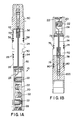
- the gun module 10 comprises gun section 20, the gun section further comprising shaped charges 22 held in a helical configuration. Any other configuration pattern of charges as is well known in the art could be used with the inventive concept.
- the perforating gun section 20 is shown as a single perforating gun in this preferred embodiment, it is to be understood that the gun section could consist of one, two, or more perforating guns connected together, as long as the finally constructed perforating gun module can be fitted into a pressure test chamber.
- the shaped charges are explosively connected via a detonation cord 24. The detonation cord is used to explosively transfer down the length of the gun section 20, thereby sequentially detonating each of the shaped charges 22 in rapid succession.
- inventive concept is being shown here with a fairly typical gun section. In fact, the inventive concept could be used with any type of perforating gun.
- first tandem connector 30 which is connected to the gun section 20.
- the tandem connector has threads 32 which are complementary to threads 26 on the gun section 20.
- Two o-rings 28 are seated in o-ring grooves 34, and are sealingly captured between the gun section 20 and the first tandem section 30 when the gun section and tandem section are screwed together.
- the connection between gun section threads 26 and tandem threads 32, along with the captured o-rings 28, create a pressure-tight seal which will be tested during the pressure testing phase, such testing being described later.
- the detonation cord 24 continues through the first tandem section 30, to provide a continuous path for the explosive transfer, being connected finally to a firing device 36.
- the gun module 10 further comprises a second tandem section 70, which is connected to the other end of the gun section 20.
- the second tandem section 70 is similar to first tandem section 30.
- the tandem section 70 has threads 72 which are complementary to threads 73 on the gun section 20.
- Two o-rings 74 are seated in o-ring grooves 76, and are sealingly captured between the gun section 20 and the second tandem section 70 when the gun section and tandem section are screwed together.
- the connection between gun section threads 72 and tandem threads 73, along with the captured o-rings 74, create a pressure-tight seal which will be tested during the pressure testing phase, such testing being described later.
- the gun module 10 further comprises a first pressure test connector 50, which is connected to the first tandem section 30.
- the first pressure test connector is connected by threads 52 which complementarily fit with threads 54 on the tandem.
- Two o-rings 56 are seated in grooves 58, and are sealingly captured between the gun section first pressure test connector 50 and the first tandem section 30 when the pressure test connector and the tandem section are screwed together.
- the connection between the first pressure test connector 50 and the first tandem section 30, along with the captured o-rings 56 create a pressure-tight seal which will also be tested during the pressure testing phase.
- the gun module 10 further comprises a second pressure test connector 200, which is connected to the second tandem section 70 in a similar fashion, and described in more detail later.
- the first pressure test connector 50 defines a housing cavity 60 therein.
- Pressure test connector 50 has a wall portion 106 which closes the upper end of housing cavity 60.
- An explosive device 84 is disposed in housing cavity 60, and is adapted to provide an explosive transfer between gun modules.
- Explosive device 84 comprises an insert 88 which is held in housing cavity 60 by a retaining means, such as the frictional engagement of an o-ring 90.
- a booster 92 is disposed in the lower end of insert 88.
- Booster 92 has a metallic portion 94 which is crimped around one end of a length of detonation cord 96.
- a detonation cord initiator 98 has a metallic portion 100 which is crimped around the other end of detonation cord 96.
- Detonation cord initiator 98 also includes a powder charge 102.
- a shaped charge 104 having a conical cavity 105 therein is positioned adjacent to charge 102.
- the second pressure test connector 200 has threads 78 which are complementary to threads 79 on the second tandem section 70.
- Two o-rings 80 are seated in o-ring grooves 82, and are sealingly captured between the second pressure test connector 200 and the second tandem section 70 when the second pressure test connector and tandem section are screwed together.
- a second explosive device 86 is made of components substantially identical to the first explosive device 84 shown in FIG. 2. This second explosive device 86 is disposed in the second housing cavity 210 and is adapted for providing an explosive transfer between connecting pressure test connectors, thereby providing a bi-directional explosive path. While the explosive transfer assembly disclosed herein is substantially the same as disclosed in U.S. Patent No. 5,603, 379, any type of explosive transfer mechanism would work.
- second pressure test connector 200 is shown being separate from the tandem section, they could be manufactured as a single pressure test connector.
- Second pressure test connector 200 has a wall portion 108 which closes the lower end of housing cavity 210.
- wall portions 106 and 108 are adjacent to one another. It will be seen that wall portions 106 and 108 separate housing cavities 60 and 210.
- wall portions 106 and 108 are made of steel, and thus, provide a leak-proof steel barrier between first and second explosive devices 84 and 86. Hence, even if well fluids come between pressure test connectors 50 and 200, the guns will not be affected.
- the gun module is first assembled by threadedly connecting appropriate first and second tandem sections 30, 70 to the gun section 20, with o-rings 28,74 in place. Then first and second pressure test connectors 50, 200 are threadedly attached to their respective tandem sections, with o-rings 56, 80 in place. All these connections are torqued to appropriate levels. Then the entire gun module is placed in a test cell, and pressure tested, preferably with liquid. Once a gun module has passed pressure testing, the module is left intact and not disassembled, and is ready for running into the hole.
- spacer modules can be prepared, the only difference being that the spacer modules have no shape charges, and are instead used to transfer the detonation to other gun or spacer modules further along.
- a firing system may also be prepared and pressure tested in a similar fashion.
- the firing system may be connected to the gun assembly as it is being inserted into the well, or added later after the rest of the gun assembly is in position in the hole.
- the gun modules and/or spacer modules are connected together, as shown in FIG. 4.
- the modules 212 and 214 are shown connected by a swivel connection 220, as taught in detail in US Patent No. 5,603,379.
- the gun modules can also be connected via mutually complementary threads, or by any number of other means as are well known in the art.
- the only possible leak path will be at the connection between modules, and this leak path is of no importance, as it will not allow fluids to enter the modules, or to thereby affect the guns.
- the modules, and thereby the entire gun assembly are pressure safe.
Landscapes
- Life Sciences & Earth Sciences (AREA)
- Engineering & Computer Science (AREA)
- Geology (AREA)
- Mining & Mineral Resources (AREA)
- Physics & Mathematics (AREA)
- Environmental & Geological Engineering (AREA)
- Fluid Mechanics (AREA)
- General Life Sciences & Earth Sciences (AREA)
- Geochemistry & Mineralogy (AREA)
- Testing Of Devices, Machine Parts, Or Other Structures Thereof (AREA)
- Particle Formation And Scattering Control In Inkjet Printers (AREA)
Applications Claiming Priority (2)
| Application Number | Priority Date | Filing Date | Title |
|---|---|---|---|
| US8919 | 1998-01-20 | ||
| US09/008,919 US6006833A (en) | 1998-01-20 | 1998-01-20 | Method for creating leak-tested perforating gun assemblies |
Publications (2)
| Publication Number | Publication Date |
|---|---|
| EP0931907A2 true EP0931907A2 (de) | 1999-07-28 |
| EP0931907A3 EP0931907A3 (de) | 2000-10-11 |
Family
ID=21734480
Family Applications (1)
| Application Number | Title | Priority Date | Filing Date |
|---|---|---|---|
| EP99300214A Withdrawn EP0931907A3 (de) | 1998-01-20 | 1999-01-14 | Bohrlochperforator und Verfahren zu dessen Herstellung |
Country Status (4)
| Country | Link |
|---|---|
| US (1) | US6006833A (de) |
| EP (1) | EP0931907A3 (de) |
| CA (1) | CA2260087A1 (de) |
| NO (1) | NO990233L (de) |
Cited By (6)
| Publication number | Priority date | Publication date | Assignee | Title |
|---|---|---|---|---|
| WO2015156771A1 (en) * | 2014-04-08 | 2015-10-15 | Halliburton Energy Services, Inc. | Perforating gun connectors |
| US10087727B2 (en) | 2016-02-04 | 2018-10-02 | Weatherford Technology Holdings, Llc | Exposed energetic device initiation via tubing conveyed firing mechanism |
| US10221661B2 (en) | 2015-12-22 | 2019-03-05 | Weatherford Technology Holdings, Llc | Pump-through perforating gun combining perforation with other operation |
| WO2022159118A1 (en) * | 2021-01-21 | 2022-07-28 | Halliburton Energy Services, Inc. | Perforating gun assembly for use within a borehole |
| US11441407B2 (en) * | 2020-06-15 | 2022-09-13 | Saudi Arabian Oil Company | Sheath encapsulation to convey acid to formation fracture |
| DE102021109782B4 (de) * | 2020-05-18 | 2024-12-24 | Halliburton Energy Services, Inc. | Außengewindelose Trennwand für Perforierpistole |
Families Citing this family (65)
| Publication number | Priority date | Publication date | Assignee | Title |
|---|---|---|---|---|
| US6499406B2 (en) | 2000-12-30 | 2002-12-31 | Dong Soo Shim | Blasting apparatus for forming horizontal underground cavities and blasting method using the same |
| US6851471B2 (en) | 2003-05-02 | 2005-02-08 | Halliburton Energy Services, Inc. | Perforating gun |
| US20050030036A1 (en) * | 2003-08-06 | 2005-02-10 | Baker Hughes Incorporated | Side entry leak protection for sondes |
| US7861785B2 (en) * | 2006-09-25 | 2011-01-04 | W. Lynn Frazier | Downhole perforation tool and method of subsurface fracturing |
| US7934558B2 (en) * | 2009-03-13 | 2011-05-03 | Halliburton Energy Services, Inc. | System and method for dynamically adjusting the center of gravity of a perforating apparatus |
| US9488456B2 (en) | 2012-01-13 | 2016-11-08 | Los Alamos National Security, Llc | Geologic fracturing method and resulting fractured geologic structure |
| US10273792B2 (en) | 2013-07-15 | 2019-04-30 | Triad National Security, Llc | Multi-stage geologic fracturing |
| US10294767B2 (en) | 2013-07-15 | 2019-05-21 | Triad National Security, Llc | Fluid transport systems for use in a downhole explosive fracturing system |
| US10246982B2 (en) | 2013-07-15 | 2019-04-02 | Triad National Security, Llc | Casings for use in a system for fracturing rock within a bore |
| US9702680B2 (en) | 2013-07-18 | 2017-07-11 | Dynaenergetics Gmbh & Co. Kg | Perforation gun components and system |
| US12203350B2 (en) | 2013-07-18 | 2025-01-21 | DynaEnergetics Europe GmbH | Detonator positioning device |
| CA3070118A1 (en) * | 2013-07-18 | 2015-01-18 | DynaEnergetics Europe GmbH | Perforation gun components and system |
| CN109372475B (zh) | 2013-08-26 | 2021-05-18 | 德国德力能有限公司 | 射孔枪和雷管组件 |
| CA2941648C (en) | 2014-03-07 | 2022-08-16 | Dynaenergetics Gmbh & Co. Kg | Device and method for positioning a detonator within a perforating gun assembly |
| US11293736B2 (en) | 2015-03-18 | 2022-04-05 | DynaEnergetics Europe GmbH | Electrical connector |
| US9784549B2 (en) | 2015-03-18 | 2017-10-10 | Dynaenergetics Gmbh & Co. Kg | Bulkhead assembly having a pivotable electric contact component and integrated ground apparatus |
| US10422195B2 (en) | 2015-04-02 | 2019-09-24 | Owen Oil Tools Lp | Perforating gun |
| RU2610780C1 (ru) * | 2015-12-03 | 2017-02-15 | Закрытое акционерное общество "Башвзрывтехнологии" | Модульный перфоратор |
| US10914145B2 (en) | 2019-04-01 | 2021-02-09 | PerfX Wireline Services, LLC | Bulkhead assembly for a tandem sub, and an improved tandem sub |
| US11905823B2 (en) | 2018-05-31 | 2024-02-20 | DynaEnergetics Europe GmbH | Systems and methods for marker inclusion in a wellbore |
| US11661824B2 (en) | 2018-05-31 | 2023-05-30 | DynaEnergetics Europe GmbH | Autonomous perforating drone |
| US11591885B2 (en) | 2018-05-31 | 2023-02-28 | DynaEnergetics Europe GmbH | Selective untethered drone string for downhole oil and gas wellbore operations |
| US10794159B2 (en) | 2018-05-31 | 2020-10-06 | DynaEnergetics Europe GmbH | Bottom-fire perforating drone |
| US10458213B1 (en) | 2018-07-17 | 2019-10-29 | Dynaenergetics Gmbh & Co. Kg | Positioning device for shaped charges in a perforating gun module |
| US11408279B2 (en) | 2018-08-21 | 2022-08-09 | DynaEnergetics Europe GmbH | System and method for navigating a wellbore and determining location in a wellbore |
| US12031417B2 (en) | 2018-05-31 | 2024-07-09 | DynaEnergetics Europe GmbH | Untethered drone string for downhole oil and gas wellbore operations |
| US10386168B1 (en) | 2018-06-11 | 2019-08-20 | Dynaenergetics Gmbh & Co. Kg | Conductive detonating cord for perforating gun |
| WO2022084363A1 (en) | 2020-10-20 | 2022-04-28 | DynaEnergetics Europe GmbH | Perforating gun and alignment assembly |
| US11339614B2 (en) | 2020-03-31 | 2022-05-24 | DynaEnergetics Europe GmbH | Alignment sub and orienting sub adapter |
| US11808093B2 (en) | 2018-07-17 | 2023-11-07 | DynaEnergetics Europe GmbH | Oriented perforating system |
| US11808098B2 (en) | 2018-08-20 | 2023-11-07 | DynaEnergetics Europe GmbH | System and method to deploy and control autonomous devices |
| US10597979B1 (en) | 2018-09-17 | 2020-03-24 | DynaEnergetics Europe GmbH | Inspection tool for a perforating gun segment |
| USD1034879S1 (en) | 2019-02-11 | 2024-07-09 | DynaEnergetics Europe GmbH | Gun body |
| USD1010758S1 (en) | 2019-02-11 | 2024-01-09 | DynaEnergetics Europe GmbH | Gun body |
| USD1019709S1 (en) | 2019-02-11 | 2024-03-26 | DynaEnergetics Europe GmbH | Charge holder |
| US12247467B2 (en) * | 2019-03-29 | 2025-03-11 | Halliburton Energy Services, Inc. | Sleeved gun connection |
| US11906278B2 (en) | 2019-04-01 | 2024-02-20 | XConnect, LLC | Bridged bulkheads for perforating gun assembly |
| WO2020200935A1 (en) | 2019-04-01 | 2020-10-08 | DynaEnergetics Europe GmbH | Retrievable perforating gun assembly and components |
| US11940261B2 (en) | 2019-05-09 | 2024-03-26 | XConnect, LLC | Bulkhead for a perforating gun assembly |
| US12241326B2 (en) | 2019-05-14 | 2025-03-04 | DynaEnergetics Europe GmbH | Single use setting tool for actuating a tool in a wellbore |
| US10927627B2 (en) | 2019-05-14 | 2021-02-23 | DynaEnergetics Europe GmbH | Single use setting tool for actuating a tool in a wellbore |
| US11255147B2 (en) | 2019-05-14 | 2022-02-22 | DynaEnergetics Europe GmbH | Single use setting tool for actuating a tool in a wellbore |
| US11578549B2 (en) | 2019-05-14 | 2023-02-14 | DynaEnergetics Europe GmbH | Single use setting tool for actuating a tool in a wellbore |
| WO2020249744A2 (en) | 2019-06-14 | 2020-12-17 | DynaEnergetics Europe GmbH | Perforating gun assembly with rotating shaped charge holder |
| US11834920B2 (en) | 2019-07-19 | 2023-12-05 | DynaEnergetics Europe GmbH | Ballistically actuated wellbore tool |
| US11559875B2 (en) | 2019-08-22 | 2023-01-24 | XConnect, LLC | Socket driver, and method of connecting perforating guns |
| US11946728B2 (en) | 2019-12-10 | 2024-04-02 | DynaEnergetics Europe GmbH | Initiator head with circuit board |
| WO2021122797A1 (en) | 2019-12-17 | 2021-06-24 | DynaEnergetics Europe GmbH | Modular perforating gun system |
| US12084962B2 (en) | 2020-03-16 | 2024-09-10 | DynaEnergetics Europe GmbH | Tandem seal adapter with integrated tracer material |
| USD1041608S1 (en) | 2020-03-20 | 2024-09-10 | DynaEnergetics Europe GmbH | Outer connector |
| USD981345S1 (en) | 2020-11-12 | 2023-03-21 | DynaEnergetics Europe GmbH | Shaped charge casing |
| US11988049B2 (en) | 2020-03-31 | 2024-05-21 | DynaEnergetics Europe GmbH | Alignment sub and perforating gun assembly with alignment sub |
| USD904475S1 (en) | 2020-04-29 | 2020-12-08 | DynaEnergetics Europe GmbH | Tandem sub |
| USD908754S1 (en) | 2020-04-30 | 2021-01-26 | DynaEnergetics Europe GmbH | Tandem sub |
| US11713625B2 (en) | 2021-03-03 | 2023-08-01 | DynaEnergetics Europe GmbH | Bulkhead |
| US12366142B2 (en) | 2021-03-03 | 2025-07-22 | DynaEnergetics Europe GmbH | Modular perforating gun system |
| WO2022184732A1 (en) | 2021-03-03 | 2022-09-09 | DynaEnergetics Europe GmbH | Bulkhead and tandem seal adapter |
| US11732556B2 (en) | 2021-03-03 | 2023-08-22 | DynaEnergetics Europe GmbH | Orienting perforation gun assembly |
| US12000267B2 (en) | 2021-09-24 | 2024-06-04 | DynaEnergetics Europe GmbH | Communication and location system for an autonomous frack system |
| US12253339B2 (en) | 2021-10-25 | 2025-03-18 | DynaEnergetics Europe GmbH | Adapter and shaped charge apparatus for optimized perforation jet |
| US12312925B2 (en) | 2021-12-22 | 2025-05-27 | DynaEnergetics Europe GmbH | Manually oriented internal shaped charge alignment system and method of use |
| WO2023200984A1 (en) | 2022-04-15 | 2023-10-19 | Dbk Industries, Llc | Fixed-volume setting tool |
| WO2024013338A1 (en) | 2022-07-13 | 2024-01-18 | DynaEnergetics Europe GmbH | Gas driven wireline release tool |
| US11753889B1 (en) | 2022-07-13 | 2023-09-12 | DynaEnergetics Europe GmbH | Gas driven wireline release tool |
| US12546194B2 (en) | 2023-08-04 | 2026-02-10 | DynaEnergetics Europe GmbH | Method and apparatus for automatic arming of perforating gun |
Citations (1)
| Publication number | Priority date | Publication date | Assignee | Title |
|---|---|---|---|---|
| US5603379A (en) | 1994-08-31 | 1997-02-18 | Halliburton Company | Bi-directional explosive transfer apparatus and method |
Family Cites Families (4)
| Publication number | Priority date | Publication date | Assignee | Title |
|---|---|---|---|---|
| US4919050A (en) * | 1988-12-14 | 1990-04-24 | Dobrinski John W | Well perforating device |
| US5355957A (en) * | 1992-08-28 | 1994-10-18 | Halliburton Company | Combined pressure testing and selective fired perforating systems |
| US5598891A (en) * | 1994-08-04 | 1997-02-04 | Marathon Oil Company | Apparatus and method for perforating and fracturing |
| EP0825324B1 (de) * | 1996-08-16 | 2004-11-17 | Halliburton Energy Services, Inc. | Werkzeugverbinder |
-
1998
- 1998-01-20 US US09/008,919 patent/US6006833A/en not_active Expired - Fee Related
-
1999
- 1999-01-14 EP EP99300214A patent/EP0931907A3/de not_active Withdrawn
- 1999-01-19 NO NO990233A patent/NO990233L/no not_active Application Discontinuation
- 1999-01-19 CA CA002260087A patent/CA2260087A1/en not_active Abandoned
Patent Citations (1)
| Publication number | Priority date | Publication date | Assignee | Title |
|---|---|---|---|---|
| US5603379A (en) | 1994-08-31 | 1997-02-18 | Halliburton Company | Bi-directional explosive transfer apparatus and method |
Cited By (8)
| Publication number | Priority date | Publication date | Assignee | Title |
|---|---|---|---|---|
| WO2015156771A1 (en) * | 2014-04-08 | 2015-10-15 | Halliburton Energy Services, Inc. | Perforating gun connectors |
| US10151152B2 (en) | 2014-04-08 | 2018-12-11 | Halliburton Energy Services, Inc. | Perforating gun connectors |
| US10221661B2 (en) | 2015-12-22 | 2019-03-05 | Weatherford Technology Holdings, Llc | Pump-through perforating gun combining perforation with other operation |
| US10087727B2 (en) | 2016-02-04 | 2018-10-02 | Weatherford Technology Holdings, Llc | Exposed energetic device initiation via tubing conveyed firing mechanism |
| DE102021109782B4 (de) * | 2020-05-18 | 2024-12-24 | Halliburton Energy Services, Inc. | Außengewindelose Trennwand für Perforierpistole |
| US11441407B2 (en) * | 2020-06-15 | 2022-09-13 | Saudi Arabian Oil Company | Sheath encapsulation to convey acid to formation fracture |
| WO2022159118A1 (en) * | 2021-01-21 | 2022-07-28 | Halliburton Energy Services, Inc. | Perforating gun assembly for use within a borehole |
| US11506048B2 (en) | 2021-01-21 | 2022-11-22 | Halliburton Energy Services, Inc. | Perforating gun assembly for use within a borehole |
Also Published As
| Publication number | Publication date |
|---|---|
| NO990233D0 (no) | 1999-01-19 |
| NO990233L (no) | 1999-07-21 |
| EP0931907A3 (de) | 2000-10-11 |
| US6006833A (en) | 1999-12-28 |
| CA2260087A1 (en) | 1999-07-20 |
Similar Documents
| Publication | Publication Date | Title |
|---|---|---|
| US6006833A (en) | Method for creating leak-tested perforating gun assemblies | |
| US7013977B2 (en) | Sealed connectors for automatic gun handling | |
| EP1853792B1 (de) | Vorrichtung und verfahren zum abschiessen von perforationskanonen | |
| GB2555637B (en) | Method of plugging and pressure testing a well | |
| US7441601B2 (en) | Perforation gun with integral debris trap apparatus and method of use | |
| US4648471A (en) | Control system for borehole tools | |
| US7624796B2 (en) | Arrangement of test plug | |
| CA3151264A1 (en) | Detonation system having sealed explosive initiation assembly | |
| EP0471622A1 (de) | Einrichtung zum Übertragen einer Sprengkette durch eine, von aussen unter Druck stehende nächstfolgende Sprengwand | |
| US12084962B2 (en) | Tandem seal adapter with integrated tracer material | |
| WO2021013731A1 (en) | Ballistically actuated wellbore tool | |
| CA2416180A1 (en) | Modular propellant assembly for fracturing wells | |
| CA2689315A1 (en) | Method for completing a borehole | |
| US12140016B2 (en) | Downhole sensor package | |
| WO2017070267A1 (en) | Shearable deployment bar with ballistic transfer | |
| EP0150189A1 (de) | Verfahren und vorrichtung zur prüfung der innenwände von mehreren verbundenen rohrstrecken | |
| US20120048539A1 (en) | Reservoir Pressure Monitoring | |
| RU2498044C1 (ru) | Способ ликвидации негерметичности в колонне труб | |
| CN106706288B (zh) | 一种油气井射孔器地面打靶试验装置 | |
| GB2561120A (en) | Method of plugging and pressure testing a well | |
| RU2297527C1 (ru) | Способ газодинамического воздействия в скважине и устройство для его осуществления | |
| GB2330164A (en) | Method of controlling downhole hydraulic activation circuits | |
| MXPA97005659A (en) | Punishing canyon for po pipes |
Legal Events
| Date | Code | Title | Description |
|---|---|---|---|
| PUAI | Public reference made under article 153(3) epc to a published international application that has entered the european phase |
Free format text: ORIGINAL CODE: 0009012 |
|
| AK | Designated contracting states |
Kind code of ref document: A2 Designated state(s): DE FR GB NL |
|
| AX | Request for extension of the european patent |
Free format text: AL;LT;LV;MK;RO;SI |
|
| PUAL | Search report despatched |
Free format text: ORIGINAL CODE: 0009013 |
|
| AK | Designated contracting states |
Kind code of ref document: A3 Designated state(s): AT BE CH CY DE DK ES FI FR GB GR IE IT LI LU MC NL PT SE |
|
| AX | Request for extension of the european patent |
Free format text: AL;LT;LV;MK;RO;SI |
|
| RIC1 | Information provided on ipc code assigned before grant |
Free format text: 7E 21B 43/116 A |
|
| 17P | Request for examination filed |
Effective date: 20010305 |
|
| AKX | Designation fees paid |
Free format text: DE FR GB NL |
|
| 17Q | First examination report despatched |
Effective date: 20030314 |
|
| STAA | Information on the status of an ep patent application or granted ep patent |
Free format text: STATUS: THE APPLICATION IS DEEMED TO BE WITHDRAWN |
|
| 18D | Application deemed to be withdrawn |
Effective date: 20030925 |