EP0931965A2 - Verfahren zum Verlegen von Unterwasserrohrleitung - Google Patents
Verfahren zum Verlegen von Unterwasserrohrleitung Download PDFInfo
- Publication number
- EP0931965A2 EP0931965A2 EP99100948A EP99100948A EP0931965A2 EP 0931965 A2 EP0931965 A2 EP 0931965A2 EP 99100948 A EP99100948 A EP 99100948A EP 99100948 A EP99100948 A EP 99100948A EP 0931965 A2 EP0931965 A2 EP 0931965A2
- Authority
- EP
- European Patent Office
- Prior art keywords
- underwater pipeline
- float elements
- group
- underwater
- float
- Prior art date
- Legal status (The legal status is an assumption and is not a legal conclusion. Google has not performed a legal analysis and makes no representation as to the accuracy of the status listed.)
- Withdrawn
Links
Images

Classifications
-
- F—MECHANICAL ENGINEERING; LIGHTING; HEATING; WEAPONS; BLASTING
- F16—ENGINEERING ELEMENTS AND UNITS; GENERAL MEASURES FOR PRODUCING AND MAINTAINING EFFECTIVE FUNCTIONING OF MACHINES OR INSTALLATIONS; THERMAL INSULATION IN GENERAL
- F16L—PIPES; JOINTS OR FITTINGS FOR PIPES; SUPPORTS FOR PIPES, CABLES OR PROTECTIVE TUBING; MEANS FOR THERMAL INSULATION IN GENERAL
- F16L1/00—Laying or reclaiming pipes; Repairing or joining pipes on or under water
- F16L1/12—Laying or reclaiming pipes on or under water
- F16L1/16—Laying or reclaiming pipes on or under water on the bottom
- F16L1/163—Laying or reclaiming pipes on or under water on the bottom by varying the apparent weight of the pipe during the laying operation
Definitions
- the invention relates to a method for laying underwater pipes, at soften the line along with a variety of float elements that run along the underwater pipeline are attached, floating along a route aligned and then lowered by separating the float elements is, according to the preamble of claim 1.
- the sinking state is thus in this release method by loosening the float elements initiated by the underwater pipeline.
- the sinking weight of the sinking The line adjusts itself to the buoyancy weight of the released float elements, this according to their task, the safe carrying of the underwater pipeline during the application on the surface of the water and the alignment of the underwater pipeline, is relatively large.
- the rate of descent is correspondingly high Release.
- a correction of the alignment of the underwater pipeline during the drop is difficult to do.
- the existing maritime traffic is impeded. Because during the lowering process Alignment must be difficult to make position corrections on the surface of the water with the generic method with high accuracy take place and accordingly requires a long period of time.
- the object of the present invention is to specify a laying process for underwater pipelines, in which the rate of descent the underwater pipeline can be controlled during the sinking process can.
- a first group of float elements from the Underwater pipeline leaving a second group of float elements separated the float elements of the first group and those of the second Group are arranged alternately on the underwater pipeline, and the remaining ones Float elements of the second group only for the final lowering on the Water bottom to be separated.
- the underwater pipeline carried by the full number of float elements. Now for lowering a certain number of float elements at intervals along the underwater pipeline severed. By the number of separated float elements the sinking weight of the underwater pipeline is set to different values. On in this way a controlled setting of the sinking speed is possible. Through the Selection of spaced float elements along the entire underwater pipeline, those to maintain a certain buoyancy and thus to adjust a slow descent rate on the pipeline is guaranteed that the underwater pipeline sinks slowly and evenly over its entire length and no excessive stresses occur due to different sinking speeds.
- the float elements of the first and second groups alternate or between two elements of a group two or more elements the other group. In this way, depending on the requirements, different Realize lift weights and thus sinking speeds.
- the underwater pipeline can be aligned very precisely along the route already on the water surface is not necessary.
- a slow sink rate corrections to the Alignment can still be made during the sinking process.
- An electronic one Observation and calibration is easy to do. In this way, there may be more Maritime traffic during the initial alignment process at the water surface only disabled for a short time.
- the method according to the invention can e.g. be used in such a way that the entire underwater pipeline at approximately the same rate of descent to the Moved the bottom of the water. It is also possible with the method according to the invention a defined and slow sloping lowering process with a corresponding one To achieve rolling motion on the water floor.
- the sinking weight of the underwater pipeline phased in which a group of Float elements is separated.
- a group of Float elements To a low sinking speed in shallow water to achieve, only a small number of float elements be cut off along the entire underwater pipeline. The deeper the underwater pipeline decreases, the higher the external water pressure becomes. To be a constant To maintain sink rate, further depths must be maintained at greater water depths Float elements are separated. By separating groups of float elements, each spaced across the entire underwater pipeline are controlled over the entire sinking process Set sink rate.
- the slow sinking speed Correct the position of the underwater pipeline even during the lowering process be made. Obstacles can also be avoided when laying must be circumvented. Especially in difficult topographical conditions, e.g. in installation channels or winding installation routes, this is an advantage.
- position corrections are carried out the subsea pipeline set a sink rate of zero.
- a separation of the float elements can e.g. by explosive devices and others remote controlled mechanisms take place. Almost, however, the detachment comes with reached a rip cord. This breaks the connection between a float element and the underwater pipeline and can be operated from the water surface. Such a separation of the float elements is both for the first group The following groups of float elements are also possible.
- the float elements are closed Hollow body with a wall thickness that only lasts for a limited period of time withstands the water pressure of a predetermined depth.
- the pipe elements, the air-filled are exposed to greater water pressure as the water depth increases.
- the wall thickness is calculated so that at a predetermined depth e.g. the sink rate zero due to the corresponding number of float elements the hollow body of the float element is maintained only one withstands the external water pressure for a limited period of time. After that period will the hollow body is pressed or dented. This reduces its buoyancy weight, so that the underwater pipeline again has a larger sinking weight or a higher sinking speed receives. This enables a controlled lowering process without additional mechanical devices must be provided to the float elements to disconnect from the underwater pipeline.
- the underwater pipeline is located when aligning along the laying route in swell-free Water depth.
- the float elements have a shape that enables different ones Set depths for the deployment of the underwater pipeline. This can e.g. can be achieved with elongated float elements, either parallel to the underwater pipeline or perpendicular to it in a standing orientation are arranged, i.e. enable two settings with different buoyancy
- the sink rate of the underwater pipeline is in advance determined by appropriate tests.
- those remaining on the underwater pipeline during the lowering process Float elements distributed over the entire underwater pipeline.
- the number of float elements for test purposes can be reduced accordingly of the entire underwater pipeline or the sink rate can be determined in advance on the basis of such a nature experiment.
- the method according to the invention can equally be used for PE pipes Use (polyethylene pipes) as for steel pipes.
- the output weight can by appropriate ballasting with air-filled tubes or by running in generated by water during the lowering process.
- the method is used to lower lines that during of the lowering process are filled with air and are thus provided with ballast weights, that they have sufficient buoyancy protection even in the air-filled state, i.e. the weights that are attached to the pipe and hold the pipe on the ground, are dimensioned in such a way that the buoyancy even with an empty line lying on the floor is less than the weight of the ballast weights.
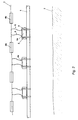
- 1 denotes an underwater pipeline, which has float elements 4 connected is.
- the float elements 4 can e.g. sealed pipe sections which are arranged at predetermined intervals along the underwater pipeline 1. The connection is maintained by bandages 5.
- the underwater pipeline is located on the water surface 3. 2 denotes the bottom of the water.
- 4b denotes float elements that come from the underwater pipeline t are separated and swim on the water surface 3. Float elements 4a are connected to the underwater pipeline 1. 6 denotes ripcords, which with the Banderoles 5 are connected.
- the method according to the invention is carried out as follows:
- a short piece of pipe, the diameter and material of the underwater pipeline corresponds with a corresponding number of float elements.
- the rate of descent of the short pipe section depending on the number of attached Float elements determined.
- the float elements are each by two bands 5 held on the underwater pipe 1.
- the underwater pipeline is now rough along the desired route aligned.
- the float tubes have a wall thickness that lasts only for a certain time withstand the respective water pressure. After this period the In this way, the float tubes bulge and reduce their buoyancy. The underwater pipeline accordingly continues to decrease.
- the Wall thicknesses can be achieved that different float tubes in different Water depths start to bulge. In this way, as in the above described embodiment of the method according to the invention in stages Achieve lowering.
- a straight piece of the underwater pipeline 1 is shown in the figures.
- the invention can also be particularly advantageous if pipe strings with large curvatures according to the prevailing topography of the Water floor must be relocated.
- the sink rate settle so low that the torsional moments that occur during of lowering onto the underwater pipeline 1, especially in curved areas act, can be kept low.
- FIG. 2 A case is shown in FIG. 2 in which the underwater pipeline 1 is connected via its entire length at the same speed in a substantially horizontal state is lowered.
- the method according to the invention can also be used advantageously, when the underwater pipe 1 is lowered obliquely and in this way on the bottom of the water is brought to roll.
- the method according to the invention enables a controlled lowering process with a slow sink rate.
- the amount of time that the underwater pipeline spends on the water surface for alignment, shortening what a one shorter maritime disability means. Because of the even slow Lowering the underwater pipeline by selecting the one to be separated Float elements are reached along the entire underwater pipeline too high tensions within the underwater pipeline during the lowering process avoided.
Landscapes
- Engineering & Computer Science (AREA)
- General Engineering & Computer Science (AREA)
- Mechanical Engineering (AREA)
- Earth Drilling (AREA)
- Pipeline Systems (AREA)
Abstract
Description
- Figur 1
- eine Unterwasserrohrleitung während des Ausbringvorganges an der Wasseroberfläche und
- Figur 2
- eine Unterwasserrohrleitung, die gemäß dem erfindungsgemäßen Verfahren abgesenkt wird.
Claims (8)
- Verfahren zum Verlegen von Unterwasserrohrleitungen, bei welchem die Leitung zusammen mit einer Vielzahl von Schwimmerelementen, die entlang der Unterwasserrohrleitung befestigt sind, schwimmend längs einer Verlegestrecke ausgerichtet und anschließend durch Abtrennen der Schwimmerelemente abgesenkt wird,
dadurch gekennzeichnet, daß
zur Steuerung der Sinkgeschwindigkeit beim Absenkvorgang eine erste Gruppe (4b) von Schwimmerelementen (4) von der Unterwasserrohrleitung (1) unter Belassung einer zweiten Gruppe von Schwimmerelementen (4a) abgetrennt wird, wobei die Schwimmerelemente der ersten Gruppe (4b) und der zweiten Gruppe (4a) alternierend an der Unterwasserrohrleitung (1) angeordnet sind, und die verbliebenen Schwimmerlelemente der zweiten Gruppe (4a) erst zum endgültigen Absenken der Unterwasserrohrleitung (1) auf den Gewässerboden (2) abgetrennt werden. - Verfahren nach Anspruch 1,
dadurch gekennzeichnet, daß
das Sinkgewicht der Unterwasserrohrleitung (1) stufenweise eingestellt wird, indem in zeitlichen Abständen jeweils eine Gruppe von Schwimmerelementen abgetrennt wird. - Verfahren nach einem der Ansprüche 1 und 2,
dadurch gekennzeichnet, daß
zur Durchführung von Lagekorrekturen der Unterwasserrohrleitung (1) während des Absenkvorganges eine Sinkgeschwindigkeit von Null eingestellt wird. - Verfahren nach einem der Ansprüche 1 bis 3,
dadurchgekennzeichnet, daß
das Abtrennen der Schwimmerelemente (4) mittels einer Reißleine erfolgt. - Verfahren nach einem der Ansprüche 1 bis 4,
dadurch gekennzeichnet, daß
die Schwimmerelemente (4) abgeschlossene Hohlköper mit einer Wandstärke sind, die nur über einen begrenzten Zeitraum dem Wasserdruck einer vorbestimmten Tiefe standhält. - Verfahren nach einem der Ansprüche 1 bis 5,
dadurch gekennzeichnet, daß
sich die Unterwasserrohrleitung (1) beim Ausrichten entlang der Verlegestrecke in wellengangsfreier Wassertiefe befindet. - Verfahren nach einem der Ansprüche 1 bis 6,
dadurch gekennzeichnet, daß
die Sinkgeschwindigkeit im vorhinein durch entsprechende Versuche ermittelt wird. - Verfahren nach einem der Ansprüche 1 bis 7,
dadurch gekennzeichnet, daß
die Unterwasserrohrleitung während des Absenkvorganges luftgefüllt ist und mit Ballastgewichten versehen ist, die auch bei abgesenkter Leitung für eine Auftriebssicherheit >1 sorgen.
Applications Claiming Priority (2)
| Application Number | Priority Date | Filing Date | Title |
|---|---|---|---|
| DE19802834A DE19802834C1 (de) | 1998-01-26 | 1998-01-26 | Verfahren zum Verlegen von Unterwasserrohrleitungen |
| DE19802834 | 1998-01-26 |
Publications (2)
| Publication Number | Publication Date |
|---|---|
| EP0931965A2 true EP0931965A2 (de) | 1999-07-28 |
| EP0931965A3 EP0931965A3 (de) | 2001-05-23 |
Family
ID=7855679
Family Applications (1)
| Application Number | Title | Priority Date | Filing Date |
|---|---|---|---|
| EP99100948A Withdrawn EP0931965A3 (de) | 1998-01-26 | 1999-01-20 | Verfahren zum Verlegen von Unterwasserrohrleitung |
Country Status (2)
| Country | Link |
|---|---|
| EP (1) | EP0931965A3 (de) |
| DE (1) | DE19802834C1 (de) |
Cited By (7)
| Publication number | Priority date | Publication date | Assignee | Title |
|---|---|---|---|---|
| DE19954430A1 (de) * | 1999-11-11 | 2001-05-31 | Karl Heinz Krah Gmbh Werkzeug | Verfahren zum Verlegen von Rohrleitungen im Meer bzw. in größeren Binnengewässern |
| US6668473B2 (en) | 2000-02-02 | 2003-12-30 | Distec Gmbh | Device for suspending posters |
| WO2005045295A1 (en) * | 2003-11-07 | 2005-05-19 | Massoud Baghernejad | Method and apparatus for laying a pipeline |
| US7155848B2 (en) | 2003-06-05 | 2007-01-02 | 501413 Ontario Limited | Apparatus for a scrolling sign |
| GB2435083A (en) * | 2006-02-10 | 2007-08-15 | Jean-Baptiste Pose | Buoyancy apparatus and method of use |
| WO2019243834A1 (en) | 2018-06-22 | 2019-12-26 | Subsea 7 Limited | Launching elongate subsea structures |
| CN115030223A (zh) * | 2022-06-02 | 2022-09-09 | 温州大学 | 一种水下悬浮隧道管体定位对接装置 |
Citations (1)
| Publication number | Priority date | Publication date | Assignee | Title |
|---|---|---|---|---|
| DE4307922C1 (de) | 1993-03-12 | 1994-08-18 | Riepl Josef Bau Ag | Verfahren zum Verlegen einer Unterwasserleitung |
Family Cites Families (2)
| Publication number | Priority date | Publication date | Assignee | Title |
|---|---|---|---|---|
| FR2305672A1 (fr) * | 1975-03-27 | 1976-10-22 | Doris Dev Richesse Sous Marine | Pose de canalisations sous-marines |
| FR2338444A1 (fr) * | 1976-01-16 | 1977-08-12 | Doris Dev Richesse Sous Marine | Pose de conduites sous-marines |
-
1998
- 1998-01-26 DE DE19802834A patent/DE19802834C1/de not_active Expired - Fee Related
-
1999
- 1999-01-20 EP EP99100948A patent/EP0931965A3/de not_active Withdrawn
Patent Citations (1)
| Publication number | Priority date | Publication date | Assignee | Title |
|---|---|---|---|---|
| DE4307922C1 (de) | 1993-03-12 | 1994-08-18 | Riepl Josef Bau Ag | Verfahren zum Verlegen einer Unterwasserleitung |
Cited By (10)
| Publication number | Priority date | Publication date | Assignee | Title |
|---|---|---|---|---|
| DE19954430A1 (de) * | 1999-11-11 | 2001-05-31 | Karl Heinz Krah Gmbh Werkzeug | Verfahren zum Verlegen von Rohrleitungen im Meer bzw. in größeren Binnengewässern |
| US6668473B2 (en) | 2000-02-02 | 2003-12-30 | Distec Gmbh | Device for suspending posters |
| US7155848B2 (en) | 2003-06-05 | 2007-01-02 | 501413 Ontario Limited | Apparatus for a scrolling sign |
| WO2005045295A1 (en) * | 2003-11-07 | 2005-05-19 | Massoud Baghernejad | Method and apparatus for laying a pipeline |
| US7470088B2 (en) | 2003-11-07 | 2008-12-30 | Massoud Baghernejad | Method and apparatus for laying a pipeline |
| GB2435083A (en) * | 2006-02-10 | 2007-08-15 | Jean-Baptiste Pose | Buoyancy apparatus and method of use |
| WO2019243834A1 (en) | 2018-06-22 | 2019-12-26 | Subsea 7 Limited | Launching elongate subsea structures |
| US11884368B2 (en) | 2018-06-22 | 2024-01-30 | Subsea 7 Limited | Launching elongate subsea structures |
| CN115030223A (zh) * | 2022-06-02 | 2022-09-09 | 温州大学 | 一种水下悬浮隧道管体定位对接装置 |
| CN115030223B (zh) * | 2022-06-02 | 2024-02-06 | 温州大学 | 一种水下悬浮隧道管体定位对接装置 |
Also Published As
| Publication number | Publication date |
|---|---|
| EP0931965A3 (de) | 2001-05-23 |
| DE19802834C1 (de) | 1999-03-11 |
Similar Documents
| Publication | Publication Date | Title |
|---|---|---|
| DE3035905A1 (de) | Vorrichtung zur fernuebertragung von informationen aus einem bohrloch zur erdoberflaeche waehrend des betriebs eines bohrgeraetes | |
| DE19802834C1 (de) | Verfahren zum Verlegen von Unterwasserrohrleitungen | |
| EP2712964B1 (de) | Vorrichtung und Verfahren zum Einbringen eines Verfüllmaterials | |
| DE2232232B2 (de) | Vorrichtung zum verlegen von in buendeln zusammengefassten rohrleitungen | |
| DE2325020A1 (de) | Grundbauteil fuer eine bohrinsel | |
| WO2012056011A1 (de) | Verfahren zum unterirdischen einbringen einer rohrleitung | |
| DE19718414C2 (de) | Verfahren zum Auskleiden eines Kanals mit Folie | |
| EP0615593A1 (de) | Spannweiten-unterstützung für unterwasser-rohrleitungen | |
| DE2002384A1 (de) | Kuenstlicher Seetang und Verfahren zum Verankern des Seetangs im Boden eines Gewaessers | |
| DE102007049606A1 (de) | Verfahren und Vorrichtung zum Einziehen eines aus Kurzrohren zusammengesetzten Rohrstranges in einen Bohrkanal | |
| DE2028859C3 (de) | Einrichtung zum Heranbringen einer auf dem Boden eines Gewässers verlegten Rohrleitung an eine küstennahe Arbeitsplattform | |
| DE4222789C1 (en) | Ballasting arrangement for underwater pipe - has identical ballast blocks clamped at equal intervals to pipe which is flooded to lower it to sea bed. | |
| DE19710465C2 (de) | Verfahren zum Verlegen von Unterwasserrohrleitungen und Vorrichtung zur Durchführung des Verfahrens | |
| DE102011108222B3 (de) | Kanalabdichtung | |
| DE3021558A1 (de) | Verfahren zum verrohren von mit fluessigkeit gefuellten bohrloechern o.dgl. unter verwendung von einzelnen rohrschuessen | |
| AT401284B (de) | Verfahren zum verlegen einer unterwasserleitung und vorrichtung zur durchführung dieses verfahrens | |
| DE2409962C3 (de) | Verfahren zum Verlegen von Unterwasserleitungen | |
| DE1750703C3 (de) | Einrichtung zum Heranbringen einer auf dem Boden eines Gewässers verlegten Rohrleitung an eine Arbeitsplattform oberhalb des Wasserspiegels | |
| DE102018121385A1 (de) | Rückbau von Hohlpfählen mittels helixförmigen Schnitts | |
| DE102007034109A1 (de) | Vorrichtung zum Zentrieren von gestängegeführten Erdbohrköpfen | |
| DE10342051B3 (de) | Verfahren zum Verlegen einer Rohrleitung durch ein Gewässer | |
| DE102013003639B3 (de) | Vorrichtung und Verfahren zum Abführen eines aus dem Meeresgrund hervorquellenden Materials | |
| DE3046077C2 (de) | Arbeitsgerät für die Schweißverbindung von Rohrstücken | |
| DE2932195C2 (de) | Verfahren und Vorrichtung zum Abdichten von außer Kontrolle geratenen Ölbohrlöchern | |
| DE2409962A1 (de) | Verfahren und vorrichtung zum verlegen von unterwasser-leitungen |
Legal Events
| Date | Code | Title | Description |
|---|---|---|---|
| PUAI | Public reference made under article 153(3) epc to a published international application that has entered the european phase |
Free format text: ORIGINAL CODE: 0009012 |
|
| AK | Designated contracting states |
Kind code of ref document: A2 Designated state(s): AT BE CH CY DE DK ES FI FR GB GR IE IT LI LU MC NL PT SE |
|
| AX | Request for extension of the european patent |
Free format text: AL;LT;LV;MK;RO;SI |
|
| PUAL | Search report despatched |
Free format text: ORIGINAL CODE: 0009013 |
|
| AK | Designated contracting states |
Kind code of ref document: A3 Designated state(s): AT BE CH CY DE DK ES FI FR GB GR IE IT LI LU MC NL PT SE |
|
| AX | Request for extension of the european patent |
Free format text: AL;LT;LV;MK;RO;SI |
|
| RIC1 | Information provided on ipc code assigned before grant |
Free format text: 7F 16L 1/12 A, 7F 16L 1/14 B, 7F 16L 1/16 B |
|
| RAP1 | Party data changed (applicant data changed or rights of an application transferred) |
Owner name: OESTERREICHISCHE DONAUTECHNIK GMBH Owner name: GLS BAUGESELLSCHAFT MBH & CO. KG |
|
| RIN1 | Information on inventor provided before grant (corrected) |
Inventor name: OESTERREICHISCHE DONAUTECHNIK GMBH Inventor name: GLS BAUGESELLSCHAFT MBH & CO. KG |
|
| AKX | Designation fees paid |
Inventor name: OESTERREICHISCHE DONAUTECHNIK GMBH |
|
| REG | Reference to a national code |
Ref country code: DE Ref legal event code: 8566 |
|
| STAA | Information on the status of an ep patent application or granted ep patent |
Free format text: STATUS: THE APPLICATION IS DEEMED TO BE WITHDRAWN |
|
| 18D | Application deemed to be withdrawn |
Effective date: 20011124 |