EP0931999A2 - Procédé à détendeur multiple pour la production d'oxygène - Google Patents
Procédé à détendeur multiple pour la production d'oxygène Download PDFInfo
- Publication number
- EP0931999A2 EP0931999A2 EP99300415A EP99300415A EP0931999A2 EP 0931999 A2 EP0931999 A2 EP 0931999A2 EP 99300415 A EP99300415 A EP 99300415A EP 99300415 A EP99300415 A EP 99300415A EP 0931999 A2 EP0931999 A2 EP 0931999A2
- Authority
- EP
- European Patent Office
- Prior art keywords
- stream
- column
- process stream
- liquid
- oxygen
- Prior art date
- Legal status (The legal status is an assumption and is not a legal conclusion. Google has not performed a legal analysis and makes no representation as to the accuracy of the status listed.)
- Granted
Links
- 238000000034 method Methods 0.000 title claims abstract description 138
- 230000008569 process Effects 0.000 title claims abstract description 121
- QVGXLLKOCUKJST-UHFFFAOYSA-N atomic oxygen Chemical compound [O] QVGXLLKOCUKJST-UHFFFAOYSA-N 0.000 title claims abstract description 74
- 239000001301 oxygen Substances 0.000 title claims abstract description 74
- 229910052760 oxygen Inorganic materials 0.000 title claims abstract description 74
- IJGRMHOSHXDMSA-UHFFFAOYSA-N Atomic nitrogen Chemical compound N#N IJGRMHOSHXDMSA-UHFFFAOYSA-N 0.000 claims abstract description 149
- 229910052757 nitrogen Inorganic materials 0.000 claims abstract description 75
- 239000007788 liquid Substances 0.000 claims abstract description 55
- 238000004821 distillation Methods 0.000 claims abstract description 51
- 238000005057 refrigeration Methods 0.000 claims abstract description 26
- 230000008016 vaporization Effects 0.000 claims abstract description 18
- 238000009834 vaporization Methods 0.000 claims abstract description 11
- 238000009833 condensation Methods 0.000 claims description 10
- 230000005494 condensation Effects 0.000 claims description 10
- MYMOFIZGZYHOMD-UHFFFAOYSA-N Dioxygen Chemical compound O=O MYMOFIZGZYHOMD-UHFFFAOYSA-N 0.000 description 32
- 239000000047 product Substances 0.000 description 28
- 238000010992 reflux Methods 0.000 description 11
- 238000004519 manufacturing process Methods 0.000 description 8
- XKRFYHLGVUSROY-UHFFFAOYSA-N Argon Chemical compound [Ar] XKRFYHLGVUSROY-UHFFFAOYSA-N 0.000 description 4
- 230000004048 modification Effects 0.000 description 4
- 238000012986 modification Methods 0.000 description 4
- 230000009467 reduction Effects 0.000 description 4
- 239000000498 cooling water Substances 0.000 description 3
- 238000005265 energy consumption Methods 0.000 description 3
- 230000006872 improvement Effects 0.000 description 3
- 239000012263 liquid product Substances 0.000 description 3
- 238000000926 separation method Methods 0.000 description 3
- 230000000153 supplemental effect Effects 0.000 description 3
- 238000010792 warming Methods 0.000 description 3
- CURLTUGMZLYLDI-UHFFFAOYSA-N Carbon dioxide Chemical compound O=C=O CURLTUGMZLYLDI-UHFFFAOYSA-N 0.000 description 2
- 229910052786 argon Inorganic materials 0.000 description 2
- 230000008901 benefit Effects 0.000 description 2
- 238000010586 diagram Methods 0.000 description 2
- 230000005611 electricity Effects 0.000 description 2
- 238000009835 boiling Methods 0.000 description 1
- 239000001569 carbon dioxide Substances 0.000 description 1
- 229910002092 carbon dioxide Inorganic materials 0.000 description 1
- 238000007796 conventional method Methods 0.000 description 1
- 238000001816 cooling Methods 0.000 description 1
- 230000007423 decrease Effects 0.000 description 1
- 230000007812 deficiency Effects 0.000 description 1
- 238000005194 fractionation Methods 0.000 description 1
- 229910052743 krypton Inorganic materials 0.000 description 1
- DNNSSWSSYDEUBZ-UHFFFAOYSA-N krypton atom Chemical compound [Kr] DNNSSWSSYDEUBZ-UHFFFAOYSA-N 0.000 description 1
- 150000002829 nitrogen Chemical class 0.000 description 1
- 238000011027 product recovery Methods 0.000 description 1
- 238000011084 recovery Methods 0.000 description 1
- 230000000717 retained effect Effects 0.000 description 1
- 238000005201 scrubbing Methods 0.000 description 1
- 239000002699 waste material Substances 0.000 description 1
- XLYOFNOQVPJJNP-UHFFFAOYSA-N water Substances O XLYOFNOQVPJJNP-UHFFFAOYSA-N 0.000 description 1
- 229910052724 xenon Inorganic materials 0.000 description 1
- FHNFHKCVQCLJFQ-UHFFFAOYSA-N xenon atom Chemical compound [Xe] FHNFHKCVQCLJFQ-UHFFFAOYSA-N 0.000 description 1
Images




Classifications
-
- F—MECHANICAL ENGINEERING; LIGHTING; HEATING; WEAPONS; BLASTING
- F25—REFRIGERATION OR COOLING; COMBINED HEATING AND REFRIGERATION SYSTEMS; HEAT PUMP SYSTEMS; MANUFACTURE OR STORAGE OF ICE; LIQUEFACTION SOLIDIFICATION OF GASES
- F25J—LIQUEFACTION, SOLIDIFICATION OR SEPARATION OF GASES OR GASEOUS OR LIQUEFIED GASEOUS MIXTURES BY PRESSURE AND COLD TREATMENT OR BY BRINGING THEM INTO THE SUPERCRITICAL STATE
- F25J3/00—Processes or apparatus for separating the constituents of gaseous or liquefied gaseous mixtures involving the use of liquefaction or solidification
- F25J3/02—Processes or apparatus for separating the constituents of gaseous or liquefied gaseous mixtures involving the use of liquefaction or solidification by rectification, i.e. by continuous interchange of heat and material between a vapour stream and a liquid stream
- F25J3/04—Processes or apparatus for separating the constituents of gaseous or liquefied gaseous mixtures involving the use of liquefaction or solidification by rectification, i.e. by continuous interchange of heat and material between a vapour stream and a liquid stream for air
- F25J3/04248—Generation of cold for compensating heat leaks or liquid production, e.g. by Joule-Thompson expansion
- F25J3/04284—Generation of cold for compensating heat leaks or liquid production, e.g. by Joule-Thompson expansion using internal refrigeration by open-loop gas work expansion, e.g. of intermediate or oxygen enriched (waste-)streams
- F25J3/04309—Generation of cold for compensating heat leaks or liquid production, e.g. by Joule-Thompson expansion using internal refrigeration by open-loop gas work expansion, e.g. of intermediate or oxygen enriched (waste-)streams of nitrogen
-
- F—MECHANICAL ENGINEERING; LIGHTING; HEATING; WEAPONS; BLASTING
- F25—REFRIGERATION OR COOLING; COMBINED HEATING AND REFRIGERATION SYSTEMS; HEAT PUMP SYSTEMS; MANUFACTURE OR STORAGE OF ICE; LIQUEFACTION SOLIDIFICATION OF GASES
- F25J—LIQUEFACTION, SOLIDIFICATION OR SEPARATION OF GASES OR GASEOUS OR LIQUEFIED GASEOUS MIXTURES BY PRESSURE AND COLD TREATMENT OR BY BRINGING THEM INTO THE SUPERCRITICAL STATE
- F25J3/00—Processes or apparatus for separating the constituents of gaseous or liquefied gaseous mixtures involving the use of liquefaction or solidification
- F25J3/02—Processes or apparatus for separating the constituents of gaseous or liquefied gaseous mixtures involving the use of liquefaction or solidification by rectification, i.e. by continuous interchange of heat and material between a vapour stream and a liquid stream
- F25J3/04—Processes or apparatus for separating the constituents of gaseous or liquefied gaseous mixtures involving the use of liquefaction or solidification by rectification, i.e. by continuous interchange of heat and material between a vapour stream and a liquid stream for air
- F25J3/04248—Generation of cold for compensating heat leaks or liquid production, e.g. by Joule-Thompson expansion
- F25J3/04284—Generation of cold for compensating heat leaks or liquid production, e.g. by Joule-Thompson expansion using internal refrigeration by open-loop gas work expansion, e.g. of intermediate or oxygen enriched (waste-)streams
-
- F—MECHANICAL ENGINEERING; LIGHTING; HEATING; WEAPONS; BLASTING
- F25—REFRIGERATION OR COOLING; COMBINED HEATING AND REFRIGERATION SYSTEMS; HEAT PUMP SYSTEMS; MANUFACTURE OR STORAGE OF ICE; LIQUEFACTION SOLIDIFICATION OF GASES
- F25J—LIQUEFACTION, SOLIDIFICATION OR SEPARATION OF GASES OR GASEOUS OR LIQUEFIED GASEOUS MIXTURES BY PRESSURE AND COLD TREATMENT OR BY BRINGING THEM INTO THE SUPERCRITICAL STATE
- F25J3/00—Processes or apparatus for separating the constituents of gaseous or liquefied gaseous mixtures involving the use of liquefaction or solidification
- F25J3/02—Processes or apparatus for separating the constituents of gaseous or liquefied gaseous mixtures involving the use of liquefaction or solidification by rectification, i.e. by continuous interchange of heat and material between a vapour stream and a liquid stream
- F25J3/04—Processes or apparatus for separating the constituents of gaseous or liquefied gaseous mixtures involving the use of liquefaction or solidification by rectification, i.e. by continuous interchange of heat and material between a vapour stream and a liquid stream for air
- F25J3/04248—Generation of cold for compensating heat leaks or liquid production, e.g. by Joule-Thompson expansion
- F25J3/04284—Generation of cold for compensating heat leaks or liquid production, e.g. by Joule-Thompson expansion using internal refrigeration by open-loop gas work expansion, e.g. of intermediate or oxygen enriched (waste-)streams
- F25J3/0429—Generation of cold for compensating heat leaks or liquid production, e.g. by Joule-Thompson expansion using internal refrigeration by open-loop gas work expansion, e.g. of intermediate or oxygen enriched (waste-)streams of feed air, e.g. used as waste or product air or expanded into an auxiliary column
- F25J3/04303—Lachmann expansion, i.e. expanded into oxygen producing or low pressure column
-
- F—MECHANICAL ENGINEERING; LIGHTING; HEATING; WEAPONS; BLASTING
- F25—REFRIGERATION OR COOLING; COMBINED HEATING AND REFRIGERATION SYSTEMS; HEAT PUMP SYSTEMS; MANUFACTURE OR STORAGE OF ICE; LIQUEFACTION SOLIDIFICATION OF GASES
- F25J—LIQUEFACTION, SOLIDIFICATION OR SEPARATION OF GASES OR GASEOUS OR LIQUEFIED GASEOUS MIXTURES BY PRESSURE AND COLD TREATMENT OR BY BRINGING THEM INTO THE SUPERCRITICAL STATE
- F25J3/00—Processes or apparatus for separating the constituents of gaseous or liquefied gaseous mixtures involving the use of liquefaction or solidification
- F25J3/02—Processes or apparatus for separating the constituents of gaseous or liquefied gaseous mixtures involving the use of liquefaction or solidification by rectification, i.e. by continuous interchange of heat and material between a vapour stream and a liquid stream
- F25J3/04—Processes or apparatus for separating the constituents of gaseous or liquefied gaseous mixtures involving the use of liquefaction or solidification by rectification, i.e. by continuous interchange of heat and material between a vapour stream and a liquid stream for air
- F25J3/04248—Generation of cold for compensating heat leaks or liquid production, e.g. by Joule-Thompson expansion
- F25J3/04375—Details relating to the work expansion, e.g. process parameter etc.
- F25J3/04393—Details relating to the work expansion, e.g. process parameter etc. using multiple or multistage gas work expansion
-
- F—MECHANICAL ENGINEERING; LIGHTING; HEATING; WEAPONS; BLASTING
- F25—REFRIGERATION OR COOLING; COMBINED HEATING AND REFRIGERATION SYSTEMS; HEAT PUMP SYSTEMS; MANUFACTURE OR STORAGE OF ICE; LIQUEFACTION SOLIDIFICATION OF GASES
- F25J—LIQUEFACTION, SOLIDIFICATION OR SEPARATION OF GASES OR GASEOUS OR LIQUEFIED GASEOUS MIXTURES BY PRESSURE AND COLD TREATMENT OR BY BRINGING THEM INTO THE SUPERCRITICAL STATE
- F25J3/00—Processes or apparatus for separating the constituents of gaseous or liquefied gaseous mixtures involving the use of liquefaction or solidification
- F25J3/02—Processes or apparatus for separating the constituents of gaseous or liquefied gaseous mixtures involving the use of liquefaction or solidification by rectification, i.e. by continuous interchange of heat and material between a vapour stream and a liquid stream
- F25J3/04—Processes or apparatus for separating the constituents of gaseous or liquefied gaseous mixtures involving the use of liquefaction or solidification by rectification, i.e. by continuous interchange of heat and material between a vapour stream and a liquid stream for air
- F25J3/04406—Processes or apparatus for separating the constituents of gaseous or liquefied gaseous mixtures involving the use of liquefaction or solidification by rectification, i.e. by continuous interchange of heat and material between a vapour stream and a liquid stream for air using a dual pressure main column system
- F25J3/04412—Processes or apparatus for separating the constituents of gaseous or liquefied gaseous mixtures involving the use of liquefaction or solidification by rectification, i.e. by continuous interchange of heat and material between a vapour stream and a liquid stream for air using a dual pressure main column system in a classical double column flowsheet, i.e. with thermal coupling by a main reboiler-condenser in the bottom of low pressure respectively top of high pressure column
-
- F—MECHANICAL ENGINEERING; LIGHTING; HEATING; WEAPONS; BLASTING
- F25—REFRIGERATION OR COOLING; COMBINED HEATING AND REFRIGERATION SYSTEMS; HEAT PUMP SYSTEMS; MANUFACTURE OR STORAGE OF ICE; LIQUEFACTION SOLIDIFICATION OF GASES
- F25J—LIQUEFACTION, SOLIDIFICATION OR SEPARATION OF GASES OR GASEOUS OR LIQUEFIED GASEOUS MIXTURES BY PRESSURE AND COLD TREATMENT OR BY BRINGING THEM INTO THE SUPERCRITICAL STATE
- F25J2200/00—Processes or apparatus using separation by rectification
- F25J2200/50—Processes or apparatus using separation by rectification using multiple (re-)boiler-condensers at different heights of the column
- F25J2200/54—Processes or apparatus using separation by rectification using multiple (re-)boiler-condensers at different heights of the column in the low pressure column of a double pressure main column system
-
- F—MECHANICAL ENGINEERING; LIGHTING; HEATING; WEAPONS; BLASTING
- F25—REFRIGERATION OR COOLING; COMBINED HEATING AND REFRIGERATION SYSTEMS; HEAT PUMP SYSTEMS; MANUFACTURE OR STORAGE OF ICE; LIQUEFACTION SOLIDIFICATION OF GASES
- F25J—LIQUEFACTION, SOLIDIFICATION OR SEPARATION OF GASES OR GASEOUS OR LIQUEFIED GASEOUS MIXTURES BY PRESSURE AND COLD TREATMENT OR BY BRINGING THEM INTO THE SUPERCRITICAL STATE
- F25J2215/00—Processes characterised by the type or other details of the product stream
- F25J2215/50—Oxygen or special cases, e.g. isotope-mixtures or low purity O2
-
- F—MECHANICAL ENGINEERING; LIGHTING; HEATING; WEAPONS; BLASTING
- F25—REFRIGERATION OR COOLING; COMBINED HEATING AND REFRIGERATION SYSTEMS; HEAT PUMP SYSTEMS; MANUFACTURE OR STORAGE OF ICE; LIQUEFACTION SOLIDIFICATION OF GASES
- F25J—LIQUEFACTION, SOLIDIFICATION OR SEPARATION OF GASES OR GASEOUS OR LIQUEFIED GASEOUS MIXTURES BY PRESSURE AND COLD TREATMENT OR BY BRINGING THEM INTO THE SUPERCRITICAL STATE
- F25J2250/00—Details related to the use of reboiler-condensers
- F25J2250/20—Boiler-condenser with multiple exchanger cores in parallel or with multiple re-boiling or condensing streams
-
- F—MECHANICAL ENGINEERING; LIGHTING; HEATING; WEAPONS; BLASTING
- F25—REFRIGERATION OR COOLING; COMBINED HEATING AND REFRIGERATION SYSTEMS; HEAT PUMP SYSTEMS; MANUFACTURE OR STORAGE OF ICE; LIQUEFACTION SOLIDIFICATION OF GASES
- F25J—LIQUEFACTION, SOLIDIFICATION OR SEPARATION OF GASES OR GASEOUS OR LIQUEFIED GASEOUS MIXTURES BY PRESSURE AND COLD TREATMENT OR BY BRINGING THEM INTO THE SUPERCRITICAL STATE
- F25J2250/00—Details related to the use of reboiler-condensers
- F25J2250/30—External or auxiliary boiler-condenser in general, e.g. without a specified fluid or one fluid is not a primary air component or an intermediate fluid
- F25J2250/42—One fluid being nitrogen
-
- F—MECHANICAL ENGINEERING; LIGHTING; HEATING; WEAPONS; BLASTING
- F25—REFRIGERATION OR COOLING; COMBINED HEATING AND REFRIGERATION SYSTEMS; HEAT PUMP SYSTEMS; MANUFACTURE OR STORAGE OF ICE; LIQUEFACTION SOLIDIFICATION OF GASES
- F25J—LIQUEFACTION, SOLIDIFICATION OR SEPARATION OF GASES OR GASEOUS OR LIQUEFIED GASEOUS MIXTURES BY PRESSURE AND COLD TREATMENT OR BY BRINGING THEM INTO THE SUPERCRITICAL STATE
- F25J2250/00—Details related to the use of reboiler-condensers
- F25J2250/30—External or auxiliary boiler-condenser in general, e.g. without a specified fluid or one fluid is not a primary air component or an intermediate fluid
- F25J2250/52—One fluid being oxygen enriched compared to air, e.g. "crude oxygen"
Definitions
- the present invention relates to the efficient production of oxygen by cryogenic air separation.
- the present invention relates to cryogenic air separation processes where it is attractive to produce at least a portion of the total oxygen with purity less than 99.5% and, preferably, less than 97%.
- US-A-2,753,698 discloses a method for the fractionation of air in which the total air to be separated is prefractionated in the high pressure column of a double rectifier to produce a crude (impure) liquid oxygen (crude LOX) bottoms and a gaseous nitrogen overhead.
- the so produced crude LOX is expanded to a medium pressure and is completely vaporized by heat exchange with condensing nitrogen.
- the vaporised crude oxygen is then slightly warmed, expanded against a load of power production and scrubbed in the low pressure column of the double rectifier by the nitrogen condensed within the high pressure column and entered on top of the low pressure column.
- the bottom of the low pressure column is reboiled with the nitrogen from the high pressure column.
- CGOX expansion This method of providing refrigeration will be referred to hereinafter as CGOX expansion.
- no other source of refrigeration is used.
- the conventional method of air expansion to the low pressure column is replaced by the proposed CGOX expansion.
- the improvement results because additional air is fed to the high pressure column (as no gaseous air is expanded to the low pressure column) and this results in additional nitrogen reflux being produced from the top of the high pressure column. It is stated that the amount of additional nitrogen reflux is equal to the additional amount of nitrogen in the air that is fed to the high pressure column.
- An improvement in the efficiency of scrubbing with liquid nitrogen in the upper part of the low pressure column is claimed to overcome the deficiency of boil-up in the lower part of the low pressure column.
- US-A-4,410,343 discloses a process for the production of low purity oxygen which employs a low pressure and a medium pressure column, wherein the bottoms of the low pressure column are reboiled against condensing air and the resultant air is fed into both the medium pressure and low pressure columns.
- US-A-4,704,148 discloses a process utilizing high and low pressure distillation columns for the separation of air to produce low purity oxygen and a waste nitrogen stream. Feed air from the cold end of the main heat exchangers is used to reboil the low pressure distillation column and to vaporize the low purity oxygen product. The heat duty for the column reboil and oxygen product vaporization is supplied by condensing air fractions. In this process, the air feed is split into three substreams. One of the substreams is totally condensed and used to provide reflux to both the low pressure and high pressure distillation columns.
- a second substream is partially condensed with the vapor portion of the partially condensed substream being fed to the bottom of the high pressure distillation column and the liquid portion providing reflux to the low pressure distillation column.
- the third substream is expanded to recover refrigeration and then introduced into the low pressure distillation column as column feed. Additionally, the high pressure column condenser is used as an intermediate reboiler in the low pressure column.
- US-A5,146,756 also teaches the use of two expanders to obtain large temperature differences between the cooling and warming streams in the main heat exchanger that cools the feed air stream for distillation. This is done to reduce the number of main heat exchanger cores.
- the low pressure column is run at pressures greater than 2.5 bar (250 kPa) and a portion of the nitrogen exiting from the top of the low pressure column is expanded in one of the expanders. A portion of the feed air is expanded in the second expander to the low pressure column.
- the present invention provides a process for the cryogenic distillation of air in a distillation column system that contains at least one distillation column wherein the boil-up at the bottom of the distillation column producing the oxygen product is provided by condensing a stream whose nitrogen concentration is equal to or greater than that in the feed air stream, which comprises the steps of: (a) generating work energy which is at least ten percent (10%) of the overall refrigeration demand of the distillation column system by at least one of the following two methods: (1) work expanding a first process stream with nitrogen content equal to or greater than that in the feed air and then condensing at least a portion of the expanded stream by latent heat exchange with at least one of the two liquids: (i) a liquid at an intermediate height in the distillation column producing oxygen product and (ii) one of the liquid feeds to this distillation column having an oxygen concentration equal to or, preferably, greater than the concentration of oxygen in the feed air; and (2) condensing at least a second process stream with nitrogen content equal to or greater than that in the feed air by latent
- the present invention teaches more energy efficient and cost effective cryogenic process for the production of low purity oxygen.
- the low-purity oxygen is defined as a product stream with oxygen concentration less than 99.5% and preferably less than 97%.
- the feed air is distilled by a distillation system that contains at least one distillation column.
- the boil-up at the bottom of the distillation column producing the oxygen product is provided by condensing a stream whose nitrogen concentration is either equal to or greater than that in the feed air stream.
- the invention is comprised of the following steps:
- step (a)(2) In the preferred mode, only one of the methods of work expansion from steps (a)(1) and (a)(2) is used. Also the second process stream in step (a)(2) will often be the same as the first process stream in step (a)(1).
- the distillation system is comprised of a double column system consisting of a higher pressure (HP') column and a lower pressure (LP') column. At least a portion of the feed air is fed to the HP' column. The product oxygen is produced from the bottom of the LP column.
- the first process stream in step (a)(1) or the second process stream in (a)(2) is generally a high pressure nitrogen-rich vapor stream withdrawn from the HP column.
- step (a)(1) the high pressure nitrogen-rich vapor stream is expanded and then condensed by latent heat exchange against a liquid stream at an intermediate height of the LP column or the crude liquid oxygen (crude LOX) stream that originates at the bottom of the HP column and forms the feed to the LP column.
- the pressure of the crude LOX stream is dropped to the vicinity of the LP column pressure.
- the high pressure nitrogen-rich stream can be partially warmed prior to expansion.
- step (a)(2) the high pressure nitrogen-rich stream is condensed by latent heat exchange against at least a portion of the crude LOX stream that is at a pressure higher than the LP column pressure, and the resulting vapor from the at least partial vaporization of the crude LOX is work expanded to the LP column. Prior to the work expansion, the resulting vapor from the at least partial vaporization of the crude LOX could be partially warmed.
- an oxygen-enriched liquid with oxygen content greater than air could be withdrawn from the LP column and pumped to the desired pressure greater than the LP column pressure prior to at least partial vaporization.
- the third process stream in step (b) can be any suitable process stream.
- Some examples include: a portion of feed air to the LP column; a nitrogen-rich product stream withdrawn from the HP column; and a stream withdrawn from the LP column.
- work expansion of feed to the HP column is suboptimal for this application because extra energy needs to be supplied to the incoming air.
- work expansion it is meant that when a process stream is expanded in an expander, it generates work. This work may be dissipated in an oil brake, or used to generate electricity or used to directly compress another process stream.
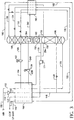
- the compressed feed air stream free of heavier components such as water and carbon dioxide is shown as stream 100.
- the feed air stream is divided into two streams, 102 and 110.
- the major fraction of stream 102 is cooled in the main heat exchanger 190 and then fed as stream 106 to the bottom of the high pressure (HP) column 196.
- the feed to the high pressure column is distilled into high pressure nitrogen vapor stream 150 at the top and the crude liquid oxygen (crude LOX) stream 130 at the bottom.
- the crude LOX stream is eventually fed to a low pressure (LP) column 198 where it is distilled to produce a lower-pressure nitrogen vapor stream 160 at the top and a liquid oxygen product stream 170 at the bottom.
- LP low pressure
- oxygen product may be withdrawn from the bottom of the LP column as vapor.
- the liquid oxygen product stream 170 is pumped by pump 171 to a desired pressure and then vaporized by heat exchange against a suitably pressurized process stream to provide gaseous oxygen product stream 172.
- the nitrogen vapor stream 160 is warmed in heat-exchanger 192 to provide stream 162 which is further warmed in main heat exchanger 190 to provide a low pressure gaseous nitrogen product (stream 164).
- the boil-up at the bottom of the LP column is provided by condensing (in reboiler/condenser 193) a first portion of the high pressure nitrogen stream from line 150 in line 152 to provide first high pressure liquid nitrogen stream 153.
- a portion of stream 153 is subcooled in heat exchanger 192 and (stream 158) reduced in pressure to provide reflux to the LP column.
- the remainder of stream 153 provides reflux to the HP column.
- step (a)(2) of the invention at least a portion (stream 134) of the crude LOX stream having a concentration of oxygen greater than that in feed air is reduced in pressure across valve 135 to a pressure which is intermediate of the HP and LP column pressures.
- crude LOX prior to pressure reduction, crude LOX is subcooled in subcooler 192 by heat exchange against the returning gaseous nitrogen stream from the LP column. This subcooling is optional.
- the pressure-reduced crude LOX stream 136 is sent to a reboiler/condenser 194, where it is at least partially boiled by latent heat exchange against the second portion of the high pressure nitrogen stream from line 150 in line 154 (the second process stream of (a)(2) of the invention) to provide the second high pressure liquid nitrogen stream 156.
- the first and second high pressure liquid nitrogen streams provide the needed reflux to the HP and LP columns.
- the vaporized portion of the pressure-reduced crude LOX stream in line 137 (hereinafter referred to as crude GOX stream) is partially warmed in the main heat exchanger 190 and then (stream 138) work expanded in expander 139 to the LP column 198 as additional feed.
- Partial warming of crude GOX stream 137 is optional and similarly, after work expansion, stream 140 could be further cooled prior to feeding it to the LP column.
- Non-vaporized pressure-reduced crude LOX from reboiler/condenser 194 (stream 142) is reduced in pressure and fed to the LP column.
- the portion of crude LOX (stream 132) not fed to the reboiler/condenser 194 is reduced in pressure and fed to a higher location of the LP column.
- step (b) of the invention a portion of the partially cooled air stream is withdrawn as stream 104 (the third process stream) from the main heat exchanger and work expanded in expander 103 and then (stream 105) fed to the LP column.
- stream 104 the third process stream
- stream 105 the third process stream
- work extracted from each expander is sent to an electric generator. This reduces the overall electric power demand.
- a portion of the feed air stream 100 in stream 110 is further boosted in an optional booster 113 and cooled against cooling water (not shown in the figure) and then (as stream 112) cooled in the main heat exchanger 190 by heat exchange against the pumped liquid oxygen stream.
- a portion of the cooled liquid air stream 118 is sent to the HP column (stream 120) and another portion (stream 122) is sent (as stream 124) to the LP column after some subcooling in subcooler 192.
- the two high pressure nitrogen streams 152 and 154 condensing in reboilers/condensers 193 and 194, respectively, may not originate from the same point in the HP column.
- Each one may be obtained at different heights of the HP column and after condensation in their reboilers (193 and 194), each is sent to an appropriate location in the distillation system.
- stream 154 could be drawn from a position which is below the top location of the high pressure column, and after condensation in reboiler/condenser 194, a portion of it could be returned to an intermediate location of the HP column and the other portion sent to the LP column.
- FIG. 2 shows an alternative embodiment where a process stream is work expanded according to step (a)(1).
- subcooled crude LOX stream 134 is let down in pressure across valve 135 to a pressure that is very close to the LP column pressure and then fed to the reboiler/condenser 194.
- the second portion of the high pressure nitrogen stream in line 154 (now the first process stream of step (a)(1)) is partially warmed (optional) in the main heat exchanger and then (stream 238) work expanded in expander 139 to provide a lower pressure nitrogen stream 240.
- This stream 240 is then condensed by latent heat exchange in reboiler/condenser 194 to provide stream 242, which after some subcooling is sent to the LP column.
- the vaporized stream 137 and the liquid stream 142 from the reboiler/condenser 194 are sent to an appropriate location in the LP column. If needed, a portion of the condensed nitrogen stream in line 242 could be pumped to the HP column.
- the two nitrogen streams, one condensing in reboiler/condenser 193 and the other condensing in reboiler/condenser 194 could be drawn from different heights of the HP column and could therefore be of different composition.
- FIG. 3 Another variation of Figure 2 using the work expansion according to step (a)(1) is shown in Figure 3.
- reboiler/condenser 194 is eliminated and all of the crude LOX stream from the bottom of the HP column is sent without any vaporization to the LP column.
- an intermediate reboiler 394 is used at an intermediate height of the LP column.
- the work expanded nitrogen stream 240 from expander 139 is condensed in reboiler/condenser 394 by latent heat exchange against a liquid at the intermediate height of the LP column.
- the condensed nitrogen stream 342 is treated in a manner which is analogous to that in Figure 2.
- the other operating features of Figure 3 are also the same as in Figure 2.
- FIGs 1-3 expansion of a portion of the feed air to the LP column is done to meet the requirement of step (b) of the invention.
- any suitable process stream for example, a stream from the LP or the HP column, may be expanded to meet the requirement of this step of the invention.
- Figure 4 shows an example where a nitrogen-rich stream from the HP column is work expanded.
- Figure 4 is analogous to Figure 1.
- Streams 104 and 105 and expander 103 are eliminated and instead, a portion of the high pressure nitrogen vapor is withdrawn from the top of the HP column in line 404.
- This stream is now the third process stream according to step (b) of the invention.
- the high pressure nitrogen in stream 404 is partially warmed in the main heat exchanger and then work expanded in expander 403.
- the work expanded stream 405 is then warmed in the main heat exchanger to provide a nitrogen stream in line 406.
- the pressure of nitrogen stream 406 may be the same or different than the nitrogen in stream 164.
- Figures 1-4 show examples where all the first or second process streams and the third process stream in steps (a) and (b) of the invention do not originate from the same process stream. Each of these two streams have different composition.
- Figure 5 shows an example where all the streams for both the steps of the invention are drawn from the top of the HP column. A portion of the high pressure nitrogen from the top of the HP column is withdrawn in line 554. This stream is then divided into two streams, 504 and 580, and both are partially warmed to their respective suitable temperatures in the main heat exchanger. After partial warming of stream 580, stream 538 provides the first process stream of step (a)(1) of the invention and is treated (streams 540 and 542) in a manner analogous to that of stream 238 in Figure 3.
- Stream 504 provides the third process stream of step (b) of the invention and is treated (expander 503 and stream 505) in a manner analogous to that of stream 404 in Figure 4. Note that in Figure 5, the work expanded nitrogen stream 505 from expander 503 is not condensed against any oxygen-rich liquid from or to the LP column in a manner taught for step (a)(1) of the invention.
- step (a)(1) not all of the first process stream after work expansion need be condensed by latent heat exchange.
- a portion of this stream may be recovered as a product stream or used for some other purpose in the process scheme.
- at least a portion of the high pressure nitrogen stream from the high pressure column is work expanded in expander 139 according to step (a)(1) of the invention.
- a portion of the stream exiting the expander 139 may be further warmed in the main heat exchanger and recovered as a nitrogen product at medium pressure from any one of these process flowsheets.
- FIG. 6 shows a process scheme analogues to that of Figure 1 in which stream 601 is withdrawn from the portion of the feed air in line 102; the withdrawn stream is then boosted in compressor 693, then cooled with cooling water (not shown in the figure) and further cooled in the main heat exchanger to provide stream 604.
- This stream 604 is further treated (expander 103 and stream 605) in a manner analogous to the treatment of stream 104 in Figure 1.
- At least a portion of the work energy needed to drive compressor 693 is derived from the expanders in the cold box.
- compressor 693 is solely driven by expander 103.
- An advantage of using such a system is that it provides a potential to extract more work from the expanders and therefore, the main heat exchanger's (190) volume is substantially reduced.
- pressure boosting of a portion of the feed air stream in line 601 it is possible to first warm other process streams which are to be work expanded in the cold box, boost their pressure in a compressor such as 693, partially cool them in appropriate heat exchanger(s) and then feed them to appropriate expander(s).
- both the expanders may be generator loaded to generate electricity or loaded with a warm compressor to compress a process stream at ambient or above ambient temperatures.
- a process stream of either steps (a) or (b) is compressed prior to expansion in such a warm compressor, the benefit is in reduction of the main heat exchangers volume.
- process streams that could be compressed in such a warm compressor are: the further pressurized air stream (stream 110 or 112 in Figure 1) that eventually condenses by heat exchange with pumped liquid oxygen, a product nitrogen stream (all or a fraction of stream 164 in Figure 1 or stream 406 in Figure 4), and a gaseous oxygen stream (line 172 in Figure 1).
- the process of the present invention is also capable of efficiently coproducing a high pressure nitrogen product stream from the HP column.
- This high pressure nitrogen product stream can be withdrawn from any suitable location of the HP column.
- This feature is not shown in any of the flowsheets 1 through 6 but is an essential part of the present invention.
- the novelty of using two expanders allows one to coproduce this high pressure nitrogen product more efficiently.
- the method taught in this invention can be used when there are coproducts besides the low-purity oxygen, with oxygen content less than 99.5%.
- a high purity (99.5% or greater oxygen content) oxygen could be coproduced from the distillation system.
- One method of accomplishing this task is to withdraw low-purity oxygen from the LP column at a location which is above the bottom and withdraw a high purity oxygen from the bottom of the LP column. If the high purity oxygen stream is withdrawn in the liquid state, it could be further boosted in pressure by a pump and then vaporized by heat exchange against a suitable process stream. Similarly, a high purity nitrogen product stream at elevated pressure could be coproduced.
- One method of accomplishing this task would be to take a portion of the condensed liquid nitrogen stream from one of the suitable reboilers/condensers and pump it to the required pressure and then vaporize it by heat exchange with a suitable process stream.
- the value of the present invention is that it leads to substantial reduction in the energy consumption. This will be demonstrated by comparing it with three known prior art processes, which are listed below:
- FIG. 7 This is a conventional double column process with an air expander to the LP column.
- the work energy from the air expander is recovered as electrical energy.
- the process of Figure 7 corresponds to the process of Figure 3 in which expander 139 and reboiler/condenser 394 and the associated lines are eliminated.
- the second prior art process is derived from US-A-4,796,431.
- the air expander 103 is eliminated. Therefore, only one expander 139 is retained to supply the total refrigeration need of the plant.
- the discharge from expander 139 is condensed against a portion of the pressure reduced crude LOX stream 136 in reboiler/condenser 194.
- the condensed nitrogen stream 242 is sent as reflux to the LP column and streams 137 and 142 from the boiling side of the reboiler/condenser 194 are sent to the LP column.
- the third prior art process is according to DE-A-2854508 and is shown in Figure 8.
- This process is similar to the one shown in Figure 7 except that the stream to be expanded is first compressed in a compressor which is mechanically linked to the expander.
- a portion 802 of the feed air stream 102 is compressed in compressor 804, cooled by heat exchange with cooling water (not shown) to give stream 806.
- This stream is then partially cooled in the main heat exchanger, work expanded in expander 803 and fed to the LP column.
- Compressor 804 and expander 803 are mechanically linked and the work energy extracted from the expander is directly transferred to the compressor.
- US-A-2,753,698 teaches that when an expander such as 139 in Figure 1 is used to expand boiled crude GOX, the improvement is obtained because an air expander is not used and total air is prefractionated in the HP column.
- Example 4 for the present invention is not taught nor suggested by US-A-2,753,698.
- DE-A-2854508 teaches that the flowsheet in Figure 8 provides additional refrigeration to produce liquid products or increase product recovery. Indeed the recovery of oxygen in the Example 3 (third prior art) is 98.04% which is higher than 95.88% for Example 4 (present invention).
- DE-A-2854508 consumes more power for low purity gaseous oxygen production. The great energy savings while using similar main heat exchanger volume is not taught or suggested by DE-A-2854508.
- the present invention is particularly useful when the HP column pressure is greater than 63 psia (4.3 bar (430 kPa) absolute) and less than 160 psia (11 bar (1,100 kPa) absolute).
- the reason being that generally a high pressure column less than 63 psia (430 kPa) requires that a portion of the feed air stream is condensed in the bottom reboiler of the LP column. This decreases the amount of liquid nitrogen reflux available to the distillation columns. Therefore, the absence of an air expander allows more air to be added to the HP column which helps create more liquid nitrogen reflux. Furthermore, since inlet pressure to expanders is now lower, the amount of work extracted is not large. For HP column pressures greater than 160 psia (1,100 kPa), the need for liquid nitrogen reflux by the distillation column increases sharply and, in this case, use of a feed air expander to the LP column could become unattractive.
Landscapes
- Engineering & Computer Science (AREA)
- Physics & Mathematics (AREA)
- Mechanical Engineering (AREA)
- Thermal Sciences (AREA)
- General Engineering & Computer Science (AREA)
- Separation By Low-Temperature Treatments (AREA)
Applications Claiming Priority (2)
| Application Number | Priority Date | Filing Date | Title |
|---|---|---|---|
| US10965 | 1998-01-22 | ||
| US09/010,965 US5956974A (en) | 1998-01-22 | 1998-01-22 | Multiple expander process to produce oxygen |
Publications (3)
| Publication Number | Publication Date |
|---|---|
| EP0931999A2 true EP0931999A2 (fr) | 1999-07-28 |
| EP0931999A3 EP0931999A3 (fr) | 1999-10-20 |
| EP0931999B1 EP0931999B1 (fr) | 2008-08-20 |
Family
ID=21748265
Family Applications (1)
| Application Number | Title | Priority Date | Filing Date |
|---|---|---|---|
| EP99300415A Expired - Lifetime EP0931999B1 (fr) | 1998-01-22 | 1999-01-21 | Procédé à détendeur multiple pour la production d'oxygène |
Country Status (8)
| Country | Link |
|---|---|
| US (1) | US5956974A (fr) |
| EP (1) | EP0931999B1 (fr) |
| JP (1) | JP3222851B2 (fr) |
| CN (1) | CN1161583C (fr) |
| CA (1) | CA2259063C (fr) |
| DE (1) | DE69939350D1 (fr) |
| ES (1) | ES2312198T3 (fr) |
| ZA (1) | ZA99401B (fr) |
Families Citing this family (8)
| Publication number | Priority date | Publication date | Assignee | Title |
|---|---|---|---|---|
| GB9806293D0 (en) * | 1998-03-24 | 1998-05-20 | Boc Group Plc | Separation of air |
| US6295840B1 (en) | 2000-11-15 | 2001-10-02 | Air Products And Chemicals, Inc. | Pressurized liquid cryogen process |
| US6494060B1 (en) * | 2001-12-04 | 2002-12-17 | Praxair Technology, Inc. | Cryogenic rectification system for producing high purity nitrogen using high pressure turboexpansion |
| FR2930629B1 (fr) * | 2008-04-23 | 2010-05-07 | Air Liquide | Appareil et procede de separation d'air par distillation cryogenique |
| EP2597409B1 (fr) * | 2011-11-24 | 2015-01-14 | L'AIR LIQUIDE, Société Anonyme pour l'Etude et l'Exploitation des Procédés Georges Claude | Procédé et installation pour la séparation de l'air par distillation cryogénique |
| EP3343159A1 (fr) * | 2016-12-28 | 2018-07-04 | Linde Aktiengesellschaft | Procédé et dispositif de production d'oxygène gazeux et azote comprimé gazeux |
| JP6842334B2 (ja) * | 2017-03-29 | 2021-03-17 | 大陽日酸株式会社 | 空気分離方法、及び空気分離装置 |
| US11054182B2 (en) | 2018-05-31 | 2021-07-06 | Air Products And Chemicals, Inc. | Process and apparatus for separating air using a split heat exchanger |
Family Cites Families (14)
| Publication number | Priority date | Publication date | Assignee | Title |
|---|---|---|---|---|
| US2753698A (en) * | 1952-03-05 | 1956-07-10 | Linde Eismasch Ag | Method and apparatus for fractionating air and power production |
| DE2854508C2 (de) * | 1978-12-16 | 1981-12-03 | Linde Ag, 6200 Wiesbaden | Verfahren und Vorrichtung zur Tieftemperaturzerlegung eines Gasgemisches |
| US4410343A (en) * | 1981-12-24 | 1983-10-18 | Union Carbide Corporation | Air boiling process to produce low purity oxygen |
| DE3307181A1 (de) * | 1983-03-01 | 1984-09-06 | Linde Ag, 6200 Wiesbaden | Verfahren und vorrichtung zur zerlegung von luft |
| US4796431A (en) * | 1986-07-15 | 1989-01-10 | Erickson Donald C | Nitrogen partial expansion refrigeration for cryogenic air separation |
| US4704148A (en) * | 1986-08-20 | 1987-11-03 | Air Products And Chemicals, Inc. | Cycle to produce low purity oxygen |
| US4883519A (en) * | 1988-10-06 | 1989-11-28 | Air Products And Chemicals, Inc. | Process for the production of high pressure nitrogen with split reboil-condensing duty |
| US4936099A (en) * | 1989-05-19 | 1990-06-26 | Air Products And Chemicals, Inc. | Air separation process for the production of oxygen-rich and nitrogen-rich products |
| GB9015377D0 (en) * | 1990-07-12 | 1990-08-29 | Boc Group Plc | Air separation |
| US5257504A (en) * | 1992-02-18 | 1993-11-02 | Air Products And Chemicals, Inc. | Multiple reboiler, double column, elevated pressure air separation cycles and their integration with gas turbines |
| GB9208645D0 (en) * | 1992-04-22 | 1992-06-10 | Boc Group Plc | Air separation |
| US5396772A (en) * | 1994-03-11 | 1995-03-14 | The Boc Group, Inc. | Atmospheric gas separation method |
| US5678427A (en) * | 1996-06-27 | 1997-10-21 | Praxair Technology, Inc. | Cryogenic rectification system for producing low purity oxygen and high purity nitrogen |
| US5839296A (en) * | 1997-09-09 | 1998-11-24 | Praxair Technology, Inc. | High pressure, improved efficiency cryogenic rectification system for low purity oxygen production |
-
1998
- 1998-01-22 US US09/010,965 patent/US5956974A/en not_active Expired - Fee Related
-
1999
- 1999-01-15 CA CA002259063A patent/CA2259063C/fr not_active Expired - Fee Related
- 1999-01-20 ZA ZA9900401A patent/ZA99401B/xx unknown
- 1999-01-21 DE DE69939350T patent/DE69939350D1/de not_active Expired - Fee Related
- 1999-01-21 ES ES99300415T patent/ES2312198T3/es not_active Expired - Lifetime
- 1999-01-21 CN CNB991013417A patent/CN1161583C/zh not_active Expired - Fee Related
- 1999-01-21 EP EP99300415A patent/EP0931999B1/fr not_active Expired - Lifetime
- 1999-01-22 JP JP01416499A patent/JP3222851B2/ja not_active Expired - Fee Related
Also Published As
| Publication number | Publication date |
|---|---|
| JPH11257846A (ja) | 1999-09-24 |
| US5956974A (en) | 1999-09-28 |
| CN1233739A (zh) | 1999-11-03 |
| ES2312198T3 (es) | 2009-02-16 |
| DE69939350D1 (de) | 2008-10-02 |
| CN1161583C (zh) | 2004-08-11 |
| JP3222851B2 (ja) | 2001-10-29 |
| ZA99401B (en) | 2000-07-20 |
| EP0931999A3 (fr) | 1999-10-20 |
| CA2259063A1 (fr) | 1999-07-22 |
| CA2259063C (fr) | 2001-04-03 |
| EP0931999B1 (fr) | 2008-08-20 |
Similar Documents
| Publication | Publication Date | Title |
|---|---|---|
| EP0932000B1 (fr) | Procédé pour la production d'oxygène | |
| US5901576A (en) | Single expander and a cold compressor process to produce oxygen | |
| US5355681A (en) | Air separation schemes for oxygen and nitrogen coproduction as gas and/or liquid products | |
| EP0556516B1 (fr) | Cycles de séparation d'air à rebouilleur, à colonne double, à pression élevée et leur intégration dans des turbines à gaz | |
| US5956973A (en) | Air separation with intermediate pressure vaporization and expansion | |
| EP0877217B1 (fr) | Séparation cryogénique d'air avec recyclage a chaud dans la turbine | |
| US4783210A (en) | Air separation process with modified single distillation column nitrogen generator | |
| US5682764A (en) | Three column cryogenic cycle for the production of impure oxygen and pure nitrogen | |
| US6009723A (en) | Elevated pressure air separation process with use of waste expansion for compression of a process stream | |
| EP0450768B1 (fr) | Génération d'azote à double rebouilleur/condenseur dans la colonne à basse pression | |
| EP0584420B1 (fr) | Cycle de séparation d'air à colonne unique et son intégration dans des turbines à gaz | |
| US5255522A (en) | Vaporization of liquid oxygen for increased argon recovery | |
| US5907959A (en) | Air separation process using warm and cold expanders | |
| US5697229A (en) | Process to produce nitrogen using a double column plus an auxiliary low pressure separation zone | |
| EP0931999B1 (fr) | Procédé à détendeur multiple pour la production d'oxygène | |
| US5682762A (en) | Process to produce high pressure nitrogen using a high pressure column and one or more lower pressure columns | |
| JP2000356465A (ja) | 空気分離用低温蒸留システム | |
| JP2000346547A (ja) | 空気分離のための極低温蒸留 | |
| US5865041A (en) | Distillation process using a mixing column to produce at least two oxygen-rich gaseous streams having different oxygen purities | |
| US20070137248A1 (en) | Method and apparatus for separating air by cryogenic distillation | |
| KR20250065327A (ko) | 중간압 케틀 컬럼을 갖는 증류 컬럼 시스템을 이용한 질소 및 아르곤의 생성을 위한 공기 분리 유닛 및 방법 | |
| EP1318368A1 (fr) | Méthode de séparation d'air pour la production d'un produit gazeux à débit variable |
Legal Events
| Date | Code | Title | Description |
|---|---|---|---|
| PUAI | Public reference made under article 153(3) epc to a published international application that has entered the european phase |
Free format text: ORIGINAL CODE: 0009012 |
|
| AK | Designated contracting states |
Kind code of ref document: A2 Designated state(s): BE DE ES FR GB IT NL |
|
| AX | Request for extension of the european patent |
Free format text: AL;LT;LV;MK;RO;SI |
|
| PUAL | Search report despatched |
Free format text: ORIGINAL CODE: 0009013 |
|
| AK | Designated contracting states |
Kind code of ref document: A3 Designated state(s): AT BE CH CY DE DK ES FI FR GB GR IE IT LI LU MC NL PT SE |
|
| AX | Request for extension of the european patent |
Free format text: AL;LT;LV;MK;RO;SI |
|
| 17P | Request for examination filed |
Effective date: 20000307 |
|
| AKX | Designation fees paid |
Free format text: BE DE ES FR GB IT NL |
|
| 17Q | First examination report despatched |
Effective date: 20020626 |
|
| APBN | Date of receipt of notice of appeal recorded |
Free format text: ORIGINAL CODE: EPIDOSNNOA2E |
|
| APBR | Date of receipt of statement of grounds of appeal recorded |
Free format text: ORIGINAL CODE: EPIDOSNNOA3E |
|
| APAZ | Date of receipt of statement of grounds of appeal deleted |
Free format text: ORIGINAL CODE: EPIDOSDNOA3E |
|
| APBR | Date of receipt of statement of grounds of appeal recorded |
Free format text: ORIGINAL CODE: EPIDOSNNOA3E |
|
| APAA | Appeal reference recorded |
Free format text: ORIGINAL CODE: EPIDOS REFN |
|
| APAF | Appeal reference modified |
Free format text: ORIGINAL CODE: EPIDOSCREFNE |
|
| APBT | Appeal procedure closed |
Free format text: ORIGINAL CODE: EPIDOSNNOA9E |
|
| GRAP | Despatch of communication of intention to grant a patent |
Free format text: ORIGINAL CODE: EPIDOSNIGR1 |
|
| GRAS | Grant fee paid |
Free format text: ORIGINAL CODE: EPIDOSNIGR3 |
|
| GRAA | (expected) grant |
Free format text: ORIGINAL CODE: 0009210 |
|
| AK | Designated contracting states |
Kind code of ref document: B1 Designated state(s): BE DE ES FR GB IT NL |
|
| REG | Reference to a national code |
Ref country code: GB Ref legal event code: FG4D |
|
| REF | Corresponds to: |
Ref document number: 69939350 Country of ref document: DE Date of ref document: 20081002 Kind code of ref document: P |
|
| REG | Reference to a national code |
Ref country code: ES Ref legal event code: FG2A Ref document number: 2312198 Country of ref document: ES Kind code of ref document: T3 |
|
| PLBE | No opposition filed within time limit |
Free format text: ORIGINAL CODE: 0009261 |
|
| STAA | Information on the status of an ep patent application or granted ep patent |
Free format text: STATUS: NO OPPOSITION FILED WITHIN TIME LIMIT |
|
| 26N | No opposition filed |
Effective date: 20090525 |
|
| GBPC | Gb: european patent ceased through non-payment of renewal fee |
Effective date: 20090121 |
|
| NLV4 | Nl: lapsed or anulled due to non-payment of the annual fee |
Effective date: 20090801 |
|
| PG25 | Lapsed in a contracting state [announced via postgrant information from national office to epo] |
Ref country code: DE Free format text: LAPSE BECAUSE OF NON-PAYMENT OF DUE FEES Effective date: 20090801 |
|
| REG | Reference to a national code |
Ref country code: FR Ref legal event code: ST Effective date: 20091030 |
|
| PG25 | Lapsed in a contracting state [announced via postgrant information from national office to epo] |
Ref country code: NL Free format text: LAPSE BECAUSE OF NON-PAYMENT OF DUE FEES Effective date: 20090801 Ref country code: GB Free format text: LAPSE BECAUSE OF NON-PAYMENT OF DUE FEES Effective date: 20090121 |
|
| PG25 | Lapsed in a contracting state [announced via postgrant information from national office to epo] |
Ref country code: BE Free format text: LAPSE BECAUSE OF NON-PAYMENT OF DUE FEES Effective date: 20090131 |
|
| REG | Reference to a national code |
Ref country code: ES Ref legal event code: FD2A Effective date: 20090122 |
|
| PG25 | Lapsed in a contracting state [announced via postgrant information from national office to epo] |
Ref country code: FR Free format text: LAPSE BECAUSE OF NON-PAYMENT OF DUE FEES Effective date: 20090202 Ref country code: ES Free format text: LAPSE BECAUSE OF NON-PAYMENT OF DUE FEES Effective date: 20090122 |
|
| PG25 | Lapsed in a contracting state [announced via postgrant information from national office to epo] |
Ref country code: IT Free format text: LAPSE BECAUSE OF NON-PAYMENT OF DUE FEES Effective date: 20090121 |