EP0932153A2 - Informationsaufzeichnungs und -wiedergabegerät - Google Patents
Informationsaufzeichnungs und -wiedergabegerät Download PDFInfo
- Publication number
- EP0932153A2 EP0932153A2 EP99300298A EP99300298A EP0932153A2 EP 0932153 A2 EP0932153 A2 EP 0932153A2 EP 99300298 A EP99300298 A EP 99300298A EP 99300298 A EP99300298 A EP 99300298A EP 0932153 A2 EP0932153 A2 EP 0932153A2
- Authority
- EP
- European Patent Office
- Prior art keywords
- information
- record
- recording
- rate
- record information
- Prior art date
- Legal status (The legal status is an assumption and is not a legal conclusion. Google has not performed a legal analysis and makes no representation as to the accuracy of the status listed.)
- Ceased
Links
Images

Classifications
-
- G—PHYSICS
- G11—INFORMATION STORAGE
- G11B—INFORMATION STORAGE BASED ON RELATIVE MOVEMENT BETWEEN RECORD CARRIER AND TRANSDUCER
- G11B20/00—Signal processing not specific to the method of recording or reproducing; Circuits therefor
- G11B20/10—Digital recording or reproducing
- G11B20/10527—Audio or video recording; Data buffering arrangements
-
- G—PHYSICS
- G11—INFORMATION STORAGE
- G11B—INFORMATION STORAGE BASED ON RELATIVE MOVEMENT BETWEEN RECORD CARRIER AND TRANSDUCER
- G11B15/00—Driving, starting or stopping record carriers of filamentary or web form; Driving both such record carriers and heads; Guiding such record carriers or containers therefor; Control thereof; Control of operating function
- G11B15/02—Control of operating function, e.g. switching from recording to reproducing
- G11B15/05—Control of operating function, e.g. switching from recording to reproducing by sensing features present on or derived from record carrier or container
- G11B15/087—Control of operating function, e.g. switching from recording to reproducing by sensing features present on or derived from record carrier or container by sensing recorded signals
-
- G—PHYSICS
- G11—INFORMATION STORAGE
- G11B—INFORMATION STORAGE BASED ON RELATIVE MOVEMENT BETWEEN RECORD CARRIER AND TRANSDUCER
- G11B27/00—Editing; Indexing; Addressing; Timing or synchronising; Monitoring; Measuring tape travel
- G11B27/005—Reproducing at a different information rate from the information rate of recording
-
- G—PHYSICS
- G11—INFORMATION STORAGE
- G11B—INFORMATION STORAGE BASED ON RELATIVE MOVEMENT BETWEEN RECORD CARRIER AND TRANSDUCER
- G11B20/00—Signal processing not specific to the method of recording or reproducing; Circuits therefor
- G11B20/10—Digital recording or reproducing
- G11B2020/10935—Digital recording or reproducing wherein a time constraint must be met
- G11B2020/10953—Concurrent recording or playback of different streams or files
- G11B2020/10962—Concurrent recording or playback of different streams or files wherein both recording and playback take place simultaneously
-
- G—PHYSICS
- G11—INFORMATION STORAGE
- G11B—INFORMATION STORAGE BASED ON RELATIVE MOVEMENT BETWEEN RECORD CARRIER AND TRANSDUCER
- G11B2220/00—Record carriers by type
- G11B2220/20—Disc-shaped record carriers
-
- G—PHYSICS
- G11—INFORMATION STORAGE
- G11B—INFORMATION STORAGE BASED ON RELATIVE MOVEMENT BETWEEN RECORD CARRIER AND TRANSDUCER
- G11B7/00—Recording or reproducing by optical means, e.g. recording using a thermal beam of optical radiation by modifying optical properties or the physical structure, reproducing using an optical beam at lower power by sensing optical properties; Record carriers therefor
- G11B7/002—Recording, reproducing or erasing systems characterised by the shape or form of the carrier
- G11B7/0037—Recording, reproducing or erasing systems characterised by the shape or form of the carrier with discs
Definitions
- the present invention generally relates to an information recording and reproducing apparatus for recording information onto a record medium and reproducing the information from the record medium, and more particularly to a control for the recording and reproducing operations in such an apparatus.
- VTR Video Tape Recorder
- the VTR there is a single head for performing the recording and reproducing operations, and the VTR has such a structure that the recording and reproducing operations are performed with respect to one video tape by use of the single head.
- a first information recording and reproducing apparatus provided with: an information recording device for generating record information by processing input information, which is inputted from the external at a predetermined input rate, and for recording the generated record information onto a record medium at a recording rate which is higher than the predetermined input rate; an information reproducing device for detecting the record information from the record medium at a predetermined detecting rate and for reproducing the detected record information by re-processing the detected record information to output the reproduced record information to the external at an output rate which is lower than the predetermined detecting rate; and a controlling device for controlling the information recording device to temporarily stop generating and/or recording the record information during a first pause time period, which is prescribed by a difference between the recording rate and the input rate, and for controlling the information reproducing device to detect and reproduce the record information, which has been recorded on the record medium by the information recording device, during the first pause time period.
- the record information when the input information is inputted from the external at the predetermined input rate, the record information is generated by processing the input information by the information recording device, and the generated record information is recorded onto the record medium at the recording rate, which is higher than the predetermined input rate.
- the record information is detected from the record medium at the predetermined detecting rate by the information reproducing device, and the detected record information is reproduced by re-processing the detected record information, so that the reproduced record information is outputted to the external at the output rate, which is lower than the predetermined detecting rate.
- the information recording device temporarily stops generating and/or recording the record information during the first pause time period, which is prescribed by the difference between the recording rate and the input rate.
- the information reproducing device detects and reproduces the record information, which has been recorded on the record medium by the information recording device, during the first pause time period.
- the operation of recording the record information and the operation of reproducing the record information which has been recorded can be apparently performed simultaneously.
- the convenience of the information recording and reproducing apparatus can be certainly improved.
- a second information recording and reproducing apparatus provided with: an information recording device for generating record information by processing input information, which is inputted from the external at a predetermined input rate, and for recording the generated record information onto a record medium at a recording rate which is higher than the predetermined input rate; an information reproducing device for detecting the record information from the record medium at a predetermined detecting rate and for reproducing the detected record information by re-processing the detected record information to output the reproduced record information to the external at an output rate which is lower than the predetermined detecting rate; and a controlling device for controlling the information reproducing device to temporarily stop detecting and/or reproducing the record information during a second pause time period, which is prescribed by a difference between the detecting rate and the output rate, and for controlling the information recording device to generate and record the record information, which has never been recorded on the record medium yet, during the second pause time period.
- the record information when the input information is inputted from the external at the predetermined input rate, the record information is generated by processing the input information by the information recording device, and the generated record information is recorded onto the record medium at the recording rate, which is higher than the predetermined input rate.
- the record information is detected from the record medium at the predetermined detecting rate by the information reproducing device, and the detected record information is reproduced by re-processing the detected record information, so that the reproduced record information is outputted to the external at the output rate, which is lower than the predetermined detecting rate.
- the information reproducing device temporarily stops detecting and/or reproducing the record information during the second pause time period, which is prescribed by the difference between the detecting rate and the output rate.
- the information recording device generates and records the record information, which has never been recorded on the record medium yet, during the second pause time period.
- the operation of recording the record information and the operation of reproducing the record information which has been recorded can be apparently performed simultaneously.
- the convenience of the information recording and reproducing apparatus can be certainly improved.
- a third information recording and reproducing apparatus provided with: an information recording device for generating record information by processing information, which is inputted from the external at a predetermined input rate, and for recording the generated record information onto a record medium at a recording rate which is higher than the predetermined input rate; an information reproducing device for detecting the record information from the record medium at a predetermined detecting rate and for reproducing the detected record information by re-processing the detected record information to output the reproduced record information to the external at an output rate which is lower than the predetermined detecting rate; and a controlling device for controlling the information recording device to temporarily stop generating and/or recording the record information during a first pause time period, which is prescribed by a difference between the recording rate and the input rate, for controlling the information reproducing device to detect and reproduce the record information, which has been recorded on the record medium by the information recording device, during the first pause time period while continuously inputting the input information from the external, for controlling the information reproducing device to temporarily stop detecting and/or
- the record information when the input information is inputted from the external at the predetermined input rate, the record information is generated by processing the input information by the information recording device, and the generated record information is recorded onto the record medium at the recording rate, which is higher than the predetermined input rate.
- the record information is detected from the record medium at the predetermined detecting rate by the information reproducing device, and the detected record information is reproduced by re-processing the detected record information, so that the reproduced record information is outputted to the external at the output rate, which is lower than the predetermined detecting rate.
- the information recording device temporarily stops generating and/or recording the record information during the first pause time period.
- the information reproducing device detects and reproduces the record information, which has been recorded on the record medium by the information recording device, during the first pause time period.
- the information reproducing device temporarily stops detecting and/or reproducing the record information during the second pause time period.
- the information recording device generates and records the record information, which has never been recorded on the record medium yet, during the second pause time period.
- the operation of recording the record information and the operation of reproducing the record information which has been recorded can be apparently performed simultaneously.
- the convenience of the information recording and reproducing apparatus can be certainly improved.
- the information recording device is provided with: a processing unit for processing the input information and generating the record information; a record information memory device for temporarily storing the generated record information; and a recording unit for reading out the record information stored in the record information memory device and recording the read out record information onto the record medium at the recording rate.
- the controlling device controls the information reproducing device to detect the record information, which has been recorded on the record medium, while controlling the information recording device to continue inputting the input information from the external during a time period in which the recording unit is not recording the record information onto the record medium and the record information memory device is storing the generated record information.
- the input information is processed and the record information is generated by the processing unit. Then, the generated record information is temporarily stored by the record information memory device. Then, the record information stored in the record information memory device is read out by the recording unit. Then, the read out record information is recorded onto the record medium at the recording rate.
- the information reproducing device detects the record information, which has been recorded on the record medium,
- the information reproducing device is provided with: a detecting unit for detecting the record information from the record medium at the detecting rate; a reproduction information memory device for temporarily storing the detected record information; and a re-processing unit for reading out the record information stored in the reproduction information memory device and for re-processing and reproducing the read out record information to output the reproduced record information to the external at the output rate.
- the controlling device controls the information recording device to record the record information onto the record medium while controlling the information reproducing device to continue outputting the reproduced record information to the external during a time period in which the detecting unit is not detecting the record information and the re-processing unit is reading out, re-processing and reproducing the record information.
- the record information is detected from the record medium at the detecting rate by the detecting unit. Then, the detected record information is temporarily stored into the reproduction information memory device. Then, the record information stored in the reproduction information memory device is read out, is reprocessed and is reproduced by the re-processing unit, so that the reproduced record information is outputted to the external at the output rate. At this time, under the control of the controlling device, while the information reproducing device continues outputting the reproduced record information to the external during the time period, in which the detecting unit is not detecting the record information and the re-processing unit is reading out, re-processing and reproducing the record information, the information recording device records the record information onto the record medium.
- the apparatus is further provided with a single optical pickup for emitting a light beam onto the record medium and receiving a reflection light of the emitted light beam reflected from the record medium to output a detection signal indicating the record information, the single optical pickup being commonly used for the information recording device and the information reproducing device.
- the light beam is emitted by the single optical pickup onto the record medium, and the reflection light of the emitted light beam reflected from the record medium is detected by the single optical pickup, so that the detection signal indicating the record information is outputted.
- the single optical pickup is commonly used for the information recording device and the information reproducing device.
- the present invention is applied to an information recording and reproducing apparatus capable of recording and reproducing the information with respect to a record medium in a disc shape (hereinafter, it is simply referred to as an "optical disc”) which can optically record and reproduce the information.
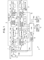
- an information recording and reproducing apparatus S is provided with: an optical pickup 2 as one example of a recording device and a detecting device; an A/D (Analog to Digital) converter 3; a compression circuit 4 as one example of a recording process device; a record buffer memory 5 as one example of a record information memory device; an encoder 6; a record circuit 7; a reproduction circuit 8; a decoder 9; a reproduction buffer memory 10 as one example of a reproduction information memory device; an expansion circuit 11 as one example of a reproduction processing device; a D/A (Digital to Analog) converter 12; a spindle motor 13; a CPU (Central Processing Unit) 14 as one example of a controlling device; a servo circuit 15; an operation unit 16; and a display unit 17.
- A/D Analog to Digital
- the optical pickup 2, the A/D converter 3, the compression circuit 4, the record buffer memory 5, the encoder 6 and the record circuit 7 constitute an information record unit R as one example of an information recording device.
- the optical pickup 2, the reproduction circuit 8, the decoder 9, the reproduction buffer memory 10, the expansion circuit 11 and the D/A converter 12 constitute an information reproduction unit P as one example of an information reproducing device.
- the A/D converter 3 digitizes the information signal Sin and generates a digital information signal Sd to output it to the compression circuit 4.
- the compression circuit 4 compresses the digital information signal Sd, which is inputted from the A/D converter 3, on the basis of a control signal S5 outputted from the CPU 14 and generates a compressed information signal Spd to output it to the record buffer memory 5.
- a compression method such as the MPEG 2 (Moving Picture coding Experts Group 2) method or the like is employed.
- the record buffer memory 5 temporarily stores the compressed information signal Spd, which is inputted from the compression circuit 4, as it is. At this time, the record buffer memory 5 consecutively outputs a data amount signal Smr, which indicates a data amount of the compressed information signal Spd accumulated in the record buffer memory 5, to the CPU 4.
- the encoder 6 reads out the compressed information signal Spd temporarily stored in the record buffer memory 5 at a recording rate Rr, which is higher than the input rate Mr of the information signal Sin, on the basis of a control signal S4 outputted from the CPU 14, and generating an encode signal Sed by encoding the compressed information signal Spd read out from the record buffer memory 5, to output it to the record circuit 7.
- the record circuit 7 converts the encode signal Sed, which is inputted from the encoder 6, into a record signal Sr on the basis of a control signal S2 outputted from the CPU 14, to output it to the optical pickup 2.
- a so-called write strategy process or the like is performed with respect to the encode signal Sed so as to form a pit in a shape, which precisely corresponds to the information to be recorded, on the optical disc 1.
- the optical pickup 2 generates a light beam B such as a laser light etc., by driving a light source such as a semiconductor laser etc., within the optical pickup 2, on the basis of the record signal Sr outputted from the record circuit 7, emits the generated light beam B onto an information record surface of the optical disc 1, and records the information signal Sin onto the optical disc 1 at a rate corresponding to the recording rate Rr by forming the pit corresponding to the record signal Sr.
- the optical disc 1 is rotated at a predetermined rotation number by the spindle motor 13, which is driven on the basis of a spindle control signal Ssm outputted from the servo circuit 15.
- the information signal Sin is recorded by forming the pit corresponding to the record signal Sr by a phase modulating method for example.
- the optical pickup 2 emits the light beam B for the reproduction onto the optical disc 1 which is being rotated, and generates a detection signal Sp corresponding to the pit formed on the optical disc 1 at a detecting rate Rp on the basis of a reflection light of the emitted light beam B.
- the reproduction circuit 8 amplifies the detection signal Sp outputted from the optical pickup 2 at a predetermined amplification factor and trims the waveform of the detection signal Sp, on the basis of a control signal S1 outputted from the CPU 14, and generates a reproduction signal Spp to output it to the decoder 9.
- the decoder 9 decodes the reproduction signal Spp by a decoding method corresponding to the encoding method in the encoder 6 on the basis of a control signal S3 outputted from the CPU 14, and generates a decode signal Sdd to outputs it to the reproduction buffer memory 10 at a rate corresponding to the detecting rate Rp.
- the reproduction buffer memory 10 temporarily stores the decode signal Sdd, which is inputted from the decoder 9, as it is. At this time, the reproduction buffer memory 10 consecutively outputs a data amount signal Smp which indicates a data amount of the decode signal Sdd accumulated in the reproduction buffer memory 10, to the CPU 14.
- the expansion circuit 11 reads out the decode signal Sdd temporarily stored in the reproduction buffer memory 10 at an output rate Mp, which is lower than the detecting rate Rp for the detection signal Sp, on the basis of a control signal S6 outputted from the CPU 14, applies an expanding process corresponding to the compressing process in the compression circuit 4 with respect to the read out decode signal Sdd, and generates an expanded signal So and outputs it to the D/A converter 12.
- the D/A converter 12 converts the expanded signal So into an analog form, and generates an output signal Sout corresponding to the information signal Sin to output it to the external device.
- the CPU 14 outputs the control signals S1 to S6 so as to perform the processes indicated by a flow chart described later, on the basis of the data amount signal Smp or Smr.
- the operation unit 16 outputs a command signal Sc, which corresponds to the operation performed on an operation panel, switches or the like thereof by the user, to the CPU 14.
- the CPU 14 outputs the control signals S1 to S6 respectively on the basis of the command signal Sc.
- the CPU 14 generates a control signal Ss for servo-controlling the spindle motor 13 and the optical pickup 2 to output it to the servo-circuit 15.
- the servo-circuit 15 generates the spindle control signal Ssm for controlling the rotation of the spindle motor 13 on the basis of the control signal Ss, and generates a pickup control signal Ssp for performing a so-called tracking servo-control and a so-called focus servo-control of the optical pickup 2, to output it to the optical pickup 2.
- the optical pickup 2 performs recording the record information Sr (information signal Sin) or detecting the detection signal Sp while performing the tracking servo-control and the focus servo-control with respect to the light beam B on the basis of the pickup control signal Ssp outputted from the servo circuit 15.
- the information necessary for the user to control the operation of the information recording and reproducing apparatus S is displayed on the display unit 17 on the basis of a display signal Sdp outputted from the CPU 14.
- FIG. 2 the processes for only reproducing the information are indicated by steps S1 to S8, the processes for only recording the information are indicated by steps S25 to S32, while the processes for simultaneously (apparently) recording and reproducing the information are indicated by steps S10 to S18.
- the position on the optical disc 1 where the record signal Sr is to be reproduced is searched, the light spot of the light beam B is moved to the searched position, and the generation of the detection signal Sp is started at the detecting rate Rp (step S1). Then, the decoding process for the generated detection signal Sp is started by the decoder 9 (step S2). When this decoding process is started, the decode signal Sdd is accumulated in the reproduction buffer memory 10 at a rate corresponding to the detecting rate Sp.
- the CPU 14 judges whether or not the empty space of the capacity in the reproduction buffer memory 10 is reduced to be equal to or less than a 1 st predetermined amount, on the basis of the data amount signal Smp outputted from the reproduction buffer memory 10 (step S3).
- the 1 st predetermined amount is set equal to a minimum decode unit of the decode signal Sdd (e.g., a data amount equal to one ECC (Error Collecting Code) block of the decode signal Sdd).
- step S3 if the empty space of the capacity in the reproduction buffer memory 10 is equal to or less than the 1 st predetermined amount (step S3: YES), since the reproduction buffer memory 10 would be full if the generation of the detection signal Sp were further continued, the optical pickup 2 is controlled to temporarily pause so as to stop the generation of the detection signal Sp (step S4). Then, the operation flow proceeds to a step S6.
- step S3 if the empty space of the capacity in the reproduction buffer memory 10 is larger than the 1 st predetermined amount (step S3: NO), the record signal Sr is further detected and the detection signal Sp is further generated (step S5).
- the CPU 14 judges whether or not the simultaneous recording operation is instructed during the reproduction through the operation unit 15 (step S6).
- step S6 if there is no instruction of the simultaneous recording operation (step S6: NO), it is judged whether or not all of the information to be reproduced is already reproduced (step S7). If the reproduction of all of the information is already completed (step S7: YES), the decoding operation by the decoder 9 is stopped (step S8). Then, the information reproducing process is ended.
- step S7 NO
- the operational flow returns to the step S3, so that the above described information reproducing process is repeated.
- step S6 if the simultaneous recording operation is instructed (step S6: YES), the compressed information signal Spd which is temporarily stored in the record buffer memory 5 (i.e., which is accumulated in the record buffer memory 5 at a rate corresponding to the input rate Mr as the A/D conversion by the A/D converter 3 for the inputted information signal Sin and the compression by the compression circuit 4 for the digital information signal Sd are performed immediately after the simultaneous recording operation is instructed at the step S6) is read out at the recording rate Rr and the process of encoding the compressed information signal Spd is started by the encoder 6 (step S9).
- the simultaneous recording operation is instructed (step S6: YES)
- the compressed information signal Spd which is temporarily stored in the record buffer memory 5 (i.e., which is accumulated in the record buffer memory 5 at a rate corresponding to the input rate Mr as the A/D conversion by the A/D converter 3 for the inputted information signal Sin and the compression by the compression circuit 4 for the digital information signal Sd are performed immediately after the simultaneous recording operation is instructed
- the CPU 14 judges whether or not the data amount accumulated in the record buffer memory 5 is increased to be equal to or larger than a 2 nd predetermined amount, which is set in advance, on the basis of the data amount signal Smr outputted from the record buffer memory 5 (step S10). If the accumulated data amount is equal to or larger than the 2 nd predetermined amount (step S10: YES), the generation of the detection signal Sp by the optical pickup 2 is controlled to temporarily pause (while the expansion circuit 11 and the D/A converter 12 are controlled by the CPU 14 to consecutively perform the expansion and the A/D conversion of the decode signal Sdd accumulated in the reproduction buffer memory 10 respectively during this pause).
- step S9 a position on the optical disc 1 where the encode signal Sed (which is encoded by the step S9) is to be recorded is searched, and the optical pickup 2 is moved to the searched position (step S11). Then, the encode signal Sed in a 3 rd predetermined amount which is set in advance is recorded onto the optical disc 1 through the optical pickup 2 (step S12).
- the 2 nd predetermined amount is set to such an amount that the record buffer memory 5 is not full even if the encode signal Sed is kept to be accumulated into the record buffer memory 5 at the input rate Mr until the operation of recording the record signal Sr is started after the completion of the judgment at the step S10 and the movement of the optical pickup 2 at the step S11, on the basis of the storage capacity Br of the record buffer memory 5.
- the 3 rd predetermined amount may be set equal to the 2 nd predetermined amount or larger than the 2 nd predetermined amount so as to output all of the encode signal Sed accumulated in the record buffer memory 5, with considering the amount of the encode signal Sed newly accumulated in the record buffer memory 5 while the record signal Sr is being recorded.
- step S13 it is judged whether or not the record signal Sr to be recorded has been completely recorded. If it is not completely recorded (step S13: NO), the operation of recording the record signal Sr by the optical pickup 2 is controlled to temporarily pause (while A/D converter 3 and the compression circuit 4 are controlled by the CPU 14 to continue the accumulation of the compressed information signal Spd into the record buffer memory 5 at the input rate Mr during this pause). Then, a position on the optical disc 1 where the record signal Sr is to be nextly reproduced is searched, and the optical pickup 2 is moved to the searched position, so as to start again the generation of the detection signal Sp in accompaniment with the decrease of the data amount accumulated in the reproduction buffer memory 10 (step S14). Then, the operational flow returns to the step S10.
- step S13 if the operation of recording the record signal Sr is completed (step S13: YES), the encoding operation by the encoder 6 is ended (step S19), a position on the optical disc 1 where the record signal Sr is to be nextly detected is searched, and the optical pickup 2 is moved to the searched position, so as to start again the information reproduction (step S20). Then, the operational flow returns to the step S3.
- step S10 if the accumulated data amount in the record buffer memory 5 is less than the 2 nd predetermined amount (step S10: NO), the CPU 14 judges whether or not the empty space of the capacity in the reproduction buffer memory 10 is reduced to be equal to or less than the 1 st predetermined amount on the basis of the data amount signal Smp outputted from the reproduction buffer memory 10 (S15).
- step S15 YES
- the optical pickup 2 is controlled to temporarily pause and the generation of the detection signal Sp is stopped in the same manner as the step S4 (step S16).
- step S18 the operational flow proceeds to a step S18. Incidentally, even at this time, the input of the information signal Sin, the accumulation of the compressed information signal Spd into the record buffer memory 5 along with the input of the information signal Sin, the output of the decode signal Sdd from the reproduction buffer memory 10 and the output of the output signal Sout from the D/A converter 12 along with the output of the output signal Sout are continued.
- step S15 if the empty space of the capacity in the reproduction buffer memory 10 is larger than the 1 st predetermined amount (step S15: NO), the record signal Sr is consecutively detected at the detecting rate Rp and the detection signal S is further generated (step S17). Then, it is judged whether or not all of the information to be reproduced is already reproduced (step S18). If the reproduction of all of the information is already completed (step S18: YES), the decoding operation by the decoder 9 is stopped (step S21). Then, a position on the optical disc 1 where the encode signal Sed (which is encoded by the step S9) is to be recorded is searched, and the optical pickup 2 is moved to the searched position (step S22). Then, the operational flow proceeds to a step S27. During the operation at the step S17, the input of the information signal Sin and the accumulation of the compressed information signal Spd into the record buffer memory 5 along with this input are continued.
- step S18 NO
- the operational flow returns to the step S10, so that the above described information reproducing process is repeated.
- the new record signal Sr may be recorded continuously in the area on the optical disc 1 other than the area where the record signal Sr has been already recorded, or may be recorded so as to overwrite the area where the record signal Sr has been already reproduced. In the latter case, since the non-recorded new area is not used, it is possible to efficiently use the recordable area of the optical disc 1.
- the compressed information signal Spd is accumulated into the record buffer memory 5 by performing the A/D converting process and the compressing process for the information signal Sin to be recorded at a rate corresponding to the input rate Mr. Then, the encoding process in the encoder 6 is started by reading out the compressed information signal Spd accumulated in the record buffer memory 5 (step S25).
- step S26 the position on the optical disc 1 where the record signal Sr is to be recorded is searched, the light spot of the light beam B is moved to the searched position, and the operation of recording the record signal Sr is performed at the recording rate Rr (step S26).
- the CPU 14 judges whether or not the empty space of the capacity in the record buffer memory 5 is increased to be equal to or larger than a 4 th predetermined amount, on the basis of the data amount signal Smr outputted from the record buffer memory 5 (step S27). If the empty space of the capacity in the record buffer memory 5 is less than the 4 th predetermined amount (step S27: NO), the operation of the optical pickup 2 for recording the record signal Sr is controlled to temporarily pause so as to wait until this empty space of the capacity reaches the 4 th predetermined amount (step S28). Then, the operational flow proceeds to a step S30. Incidentally, even at this time, the input of the information signal Sin and the accumulation of the compressed information signal Spd into the record buffer memory along with this input are continued.
- step S27 if the empty space of the capacity in the reproduction buffer memory 10 is equal to or larger than the 4 th predetermined amount (step S27: YES), the encode signal Sed (record signal Sr) in a 5 th predetermined amount, which is set in advance, is recorded onto the optical disc 1 at the recording rate Rr through the optical pickup 2.
- the 4 th predetermined amount may be any data amount as long as it is equal to or less than the 2 nd predetermined amount
- the 5 th predetermined amount may be any data amount as long as it is equal to or less than the 3 rd predetermined amount.
- the CPU 14 judges whether or not the simultaneous recording operation is instructed during the recording operation through the operation unit 15 (step S30).
- step S30 if there is no instruction of the simultaneous recording operation (step S30: NO), it is judged whether or not all of the information to be recorded is already recorded (step S31). If the recording of all of the information is already completed (step S31: YES), the encoding operation by the encoder 6 is stopped (step S32). Then, the information recording process is ended.
- step S31 NO
- the operational flow returns to the step S27, so that the above described information recording process is repeated.
- step S30 if the simultaneous recording operation is instructed (step S30: YES), the operation of the optical pickup 2 for recording the record signal Sr is controlled to temporarily pause (while the accumulation of the generated compressed information signal Spd into the record buffer memory 5 at the input rate Mr is continued as the A/D conversion by the A/D converter 3 for the inputted information signal Sin and the compression by the compression circuit 4 for the digital information signal Sd are performed under the control of the CPU 14 during this pause). Then, the position on the optical disc 1 where the record signal Sr is to be reproduced is searched, the light spot of the light beam B is moved to the searched position, and the generation of the detection signal Sp is started at the detecting rate Rp (step S33). Then, the decoding process for the generated detection signal Sp is started by the decoder 9 (step S34). When this decoding process is started, the decode signal Sdd is accumulated into the reproduction buffer memory 10 at a rate corresponding to the detecting rate Sp.
- the operational flow proceeds to the step S10, and the steps S10 to S22 are performed so as to perform the reproducing operation during the recording operation while the data amount accumulated in the record buffer memory 5 and the data amount accumulated in the reproduction buffer memory 10 are respectively monitored.
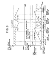
- FIG. 3 indicates the change of the data amount accumulated in each buffer in the case where the simultaneous recording operation is instructed during the reproducing operation.
- the detection of the detection signal Sp is performed in each time band indicated by a white empty area while the recording of the record signal Sr is performed in each time band indicated by a meshed area.
- the data amount accumulated in the reproduction buffer memory 10 (whose capacity is Bp) changes such that the empty space of the capacity therein is in the range of the data amount not larger than the minimum decode unit. Namely, when the empty space of the capacity becomes equal to or larger than the 1 st predetermined amount, the detection of the record signal Sr is started (at the detection rate Rp) such that the empty space of the capacity in the reproduction buffer memory 10 increases at a rate R as expressed by a following expression.
- R (detection rate Rp) - (output rate Mp).
- the detection of the record signal Sr is controlled to temporarily pause, and only the output of the output signal Sout (at the output rate Mp) is performed. These start and pause of the detection of the record signal Sr are repeated.
- the accumulation of the compressed information signal Spd into the record buffer memory 5 is started at the input rate Mr (refer to the step S9) and the data amount accumulated in the record buffer memory 5 is monitored (refer to the step S10).
- the detection of the detection signal Sp is controlled to temporarily pause, and the recording position for the new record signal Sr is searched.
- the recording of the record signal Sr is started at a time t3 (refer to the steps S11 and S12). Even at this time, the output of the decode signal Sdd from the reproduction buffer memory 10 is continued.
- the optical pickup 2 is moved to the next detecting position so as to perform the detection of the detection signal Sp again (refer to the step S14). Then, from a time t5 until the data amount accumulated in the record buffer memory 5 reaches the 2 nd predetermined amount (i.e., until a time t6), the detection of the detection signal Sp is continued.
- the data amount accumulated in reproduction buffer memory 10 decreases at the output rate Mp while the movement of the optical pickup 2 to the recording position, the actual recording of the record signal Sr and the movement of the optical pickup 2 to the detecting position are performed (i.e., from the t2 until the time t5), and increases at the above mentioned rate R after the detection of the detection signal Sp is started again. These increase and decrease of the accumulated data amount are repeated.
- the data amount accumulated in the record buffer memory 5 increases at the input rate Mr since the simultaneous recording and reproducing command is instructed during the reproduction until the movement of the optical pickup 2 to the recording position is completed (i.e., from the t1 until the time t3), and decreases at a rate R' as expressed by a following expression while the record signal Sr is actually recorded.
- R' (input rate Mr) - (recording rate Rr)
- the record signal Sr which has been recorded on the optical disc 1 can be reproduced while the input of the information from the external device is continued, and since the record signal Sr which is not recorded yet can be recorded while the output of the detected record signal Sr to the external device is continued, it is possible to simultaneously perform the recording operation and the reproducing operation apparently as a whole of the information recording and reproducing apparatus S.
- the record signal Sr which has been already recorded can be detected while the compressed information signal Spd is being stored into the record buffer memory 5, and since the record signal Sr which is not recorded yet can be recorded while the decode signal Sdd is being read out from the reproduction buffer memory 10, it is possible to simultaneously perform the recording operation and the reproducing operation by means of a relatively simplified structure.
- optical disc 1 is employed as one example of the record medium in the above mentioned embodiment, the present invention can be applied to any kind of record medium other than that as long as it enables reading and writing the information and it enables random-accessing, such as a semiconductor memory or the like.
- the present invention can be widely applied to other type of the information recording and reproducing apparatus as long as it performs the recording and reproducing operations in which the input rate of the information from the external device is lower than the recording rate of the information onto the record medium and the detecting rate of the information from the record medium is higher than the output rate of the information to the external device.
Landscapes
- Engineering & Computer Science (AREA)
- Multimedia (AREA)
- Signal Processing (AREA)
- Signal Processing For Digital Recording And Reproducing (AREA)
Applications Claiming Priority (2)
| Application Number | Priority Date | Filing Date | Title |
|---|---|---|---|
| JP983398 | 1998-01-21 | ||
| JP10009833A JPH11213555A (ja) | 1998-01-21 | 1998-01-21 | 情報記録再生装置 |
Publications (2)
| Publication Number | Publication Date |
|---|---|
| EP0932153A2 true EP0932153A2 (de) | 1999-07-28 |
| EP0932153A3 EP0932153A3 (de) | 1999-10-13 |
Family
ID=11731141
Family Applications (1)
| Application Number | Title | Priority Date | Filing Date |
|---|---|---|---|
| EP99300298A Ceased EP0932153A3 (de) | 1998-01-21 | 1999-01-18 | Informationsaufzeichnungs und -wiedergabegerät |
Country Status (3)
| Country | Link |
|---|---|
| EP (1) | EP0932153A3 (de) |
| JP (1) | JPH11213555A (de) |
| CN (1) | CN1226730A (de) |
Cited By (8)
| Publication number | Priority date | Publication date | Assignee | Title |
|---|---|---|---|---|
| WO2001035405A1 (en) * | 1999-11-10 | 2001-05-17 | Thomson Licensing S.A. | Buffer optimization for simultaneous encoding-decoding and pause-catch-up for real-time dvd recorder |
| EP1465187A1 (de) * | 2003-04-02 | 2004-10-06 | Deutsche Thomson-Brandt Gmbh | Verfahren zur Kontrolle eines optischen Abtasters zum Lesen der Datenströme und für gleichzeitige Wiedergabe |
| WO2005050641A1 (en) * | 2003-11-18 | 2005-06-02 | Koninklijke Philips Electronics N.V. | Determining buffer refilling time when playing back variable bit rate media streams |
| EP1431978A3 (de) * | 2002-12-18 | 2005-08-31 | Sony Corporation | Vorrichtung, Verfahren und Programm zur Informationsverarbeitung |
| EP1278378A4 (de) * | 2000-03-28 | 2005-11-30 | Matsushita Electric Industrial Co Ltd | Aufzeichnungsvorrichtung, spezielles wiedergabesystem, medium und informationsobjekt |
| US6985416B1 (en) | 1999-11-10 | 2006-01-10 | Thomson Licensing S.A. | Buffer optimization for simultaneous encoding-decoding and pause-catch-up for real time DVD recorder |
| US7885511B2 (en) | 2005-03-16 | 2011-02-08 | Canon Kabushiki Kaisha | Recording/reproducing apparatus and method of controlling the apparatus |
| US8218056B2 (en) | 2001-04-16 | 2012-07-10 | Canon Kabushiki Kaisha | Imaging apparatus and video camera, and method of reproducing recorded information performed by the imaging apparatus or the video camera |
Families Citing this family (3)
| Publication number | Priority date | Publication date | Assignee | Title |
|---|---|---|---|---|
| JP2004005864A (ja) | 2002-04-17 | 2004-01-08 | Pioneer Electronic Corp | 情報記録媒体、情報再生装置、情報記録装置及び情報記録再生装置 |
| JP4677467B2 (ja) * | 2008-04-15 | 2011-04-27 | キヤノン株式会社 | ビデオカメラ |
| JP2011015427A (ja) * | 2010-08-30 | 2011-01-20 | Canon Inc | 記録装置 |
Family Cites Families (10)
| Publication number | Priority date | Publication date | Assignee | Title |
|---|---|---|---|---|
| JPH05151758A (ja) * | 1991-11-28 | 1993-06-18 | Sharp Corp | 情報記録再生装置 |
| JPH06119758A (ja) * | 1992-10-05 | 1994-04-28 | Yamaha Corp | ディスク記録再生装置 |
| EP0594241B1 (de) * | 1992-10-19 | 1999-05-06 | Koninklijke Philips Electronics N.V. | Gerät zur Speicherung eines Datensignals in einem Speicher und zur Wiedergabe des Datensignals aus diesem Speicher |
| JPH06139697A (ja) * | 1992-10-29 | 1994-05-20 | Kenwood Corp | 光ディスク記録再生装置 |
| JPH06259945A (ja) * | 1993-03-09 | 1994-09-16 | Sony Corp | ディスク記録再生装置 |
| JPH0778412A (ja) * | 1993-07-13 | 1995-03-20 | Sony Corp | 記録再生装置及び方法並びに再生装置及び方法 |
| GB2287845B (en) * | 1994-03-18 | 1998-03-25 | Sony Uk Ltd | Multichannel video data storage |
| JPH08147876A (ja) * | 1994-11-14 | 1996-06-07 | Sony Corp | 記録再生装置及び記録再生方法 |
| EP1161089B1 (de) * | 1995-09-11 | 2003-12-17 | Matsushita Electric Industrial Co., Ltd. | Fernsehsignalaufnahme- und -wiedergabeanlage |
| DE69805563T2 (de) * | 1997-03-19 | 2003-01-16 | Kabushiki Kaisha Toshiba, Kawasaki | Ein Plattengerät mit einem einzelnen Aufnahmekopf fähig zum gleichzeitigen Aufnehmen und Wiedergeben |
-
1998
- 1998-01-21 JP JP10009833A patent/JPH11213555A/ja active Pending
-
1999
- 1999-01-18 EP EP99300298A patent/EP0932153A3/de not_active Ceased
- 1999-01-21 CN CN99100984.3A patent/CN1226730A/zh active Pending
Cited By (13)
| Publication number | Priority date | Publication date | Assignee | Title |
|---|---|---|---|---|
| WO2001035405A1 (en) * | 1999-11-10 | 2001-05-17 | Thomson Licensing S.A. | Buffer optimization for simultaneous encoding-decoding and pause-catch-up for real-time dvd recorder |
| US6985416B1 (en) | 1999-11-10 | 2006-01-10 | Thomson Licensing S.A. | Buffer optimization for simultaneous encoding-decoding and pause-catch-up for real time DVD recorder |
| EP1278378A4 (de) * | 2000-03-28 | 2005-11-30 | Matsushita Electric Industrial Co Ltd | Aufzeichnungsvorrichtung, spezielles wiedergabesystem, medium und informationsobjekt |
| US8520119B2 (en) | 2001-04-16 | 2013-08-27 | Canon Kabushiki Kaisha | Imaging apparatus and video camera, and method of reproducing recorded information performed by the imaging apparatus or the video camera |
| US8218056B2 (en) | 2001-04-16 | 2012-07-10 | Canon Kabushiki Kaisha | Imaging apparatus and video camera, and method of reproducing recorded information performed by the imaging apparatus or the video camera |
| EP1431978A3 (de) * | 2002-12-18 | 2005-08-31 | Sony Corporation | Vorrichtung, Verfahren und Programm zur Informationsverarbeitung |
| US7260037B2 (en) | 2002-12-18 | 2007-08-21 | Sony Corporation | Information-processing apparatus, information-processing method and information-processing program |
| US7978962B2 (en) | 2003-04-02 | 2011-07-12 | Thomson Licensing | Method for controlling an optical pick-up for reading data streams for simultaneous reproduction |
| EP1465187A1 (de) * | 2003-04-02 | 2004-10-06 | Deutsche Thomson-Brandt Gmbh | Verfahren zur Kontrolle eines optischen Abtasters zum Lesen der Datenströme und für gleichzeitige Wiedergabe |
| WO2004088660A1 (en) * | 2003-04-02 | 2004-10-14 | Thomson Licensing | Method for controlling an optical pick-up for reading data streams for simultaneous reproduction |
| WO2005050641A1 (en) * | 2003-11-18 | 2005-06-02 | Koninklijke Philips Electronics N.V. | Determining buffer refilling time when playing back variable bit rate media streams |
| US7869316B2 (en) | 2003-11-18 | 2011-01-11 | Koninklijke Philips Electronics N.V. | Determining buffer refilling time when playing back variable bit rate media streams |
| US7885511B2 (en) | 2005-03-16 | 2011-02-08 | Canon Kabushiki Kaisha | Recording/reproducing apparatus and method of controlling the apparatus |
Also Published As
| Publication number | Publication date |
|---|---|
| CN1226730A (zh) | 1999-08-25 |
| EP0932153A3 (de) | 1999-10-13 |
| JPH11213555A (ja) | 1999-08-06 |
Similar Documents
| Publication | Publication Date | Title |
|---|---|---|
| US5586093A (en) | Recording device capable of reading out data from a disk for editing and recording back to the disk | |
| JP3198550B2 (ja) | 圧縮データ記録方法及び圧縮データ記録再生装置 | |
| US5982723A (en) | Data recording and reproducing method for multi-layered optical disk system | |
| US6549496B2 (en) | Information recording apparatus and information reproducing apparatus | |
| EP0932153A2 (de) | Informationsaufzeichnungs und -wiedergabegerät | |
| US6262951B1 (en) | Information reproducing system and method capable of reproducing in desired reproducing time | |
| JPH0554525A (ja) | コンパクトデイスクプレーヤーの誤記録防止方法 | |
| US6553177B1 (en) | Information recording and reproducing system | |
| US6507541B1 (en) | Information recording apparatus | |
| JP3239480B2 (ja) | 記録方式及び記録再生方式 | |
| JPH11213556A (ja) | 情報記録装置 | |
| JP3567765B2 (ja) | 情報の記録再生装置 | |
| JP3651803B2 (ja) | 記録再生装置 | |
| EP1026890A2 (de) | Informationsaufnahme- und -Wiedergabeanlage und Informationsaufnahme- und -Wiedergabeverfahren | |
| JP2006179095A (ja) | 光ディスク装置 | |
| JPH07262691A (ja) | ディスクとその記録または再生方法 | |
| KR100618730B1 (ko) | 광 기록매체 및 간헐영상 녹화방법 | |
| JP3794815B2 (ja) | 情報記録装置 | |
| JP3591655B2 (ja) | 再生装置及び方法 | |
| US7839755B2 (en) | Information recording apparatus and information reproducing apparatus, information recording method and information reproducing method, information recording program and information reproducing program, information recording medium and recording medium | |
| JP2007080351A (ja) | 光ディスク記録再生装置 | |
| JP4030454B2 (ja) | データ記録再生装置 | |
| JP4062624B2 (ja) | 記録装置、記録方法、光学情報記録再生装置 | |
| JP2005025933A (ja) | 情報記録再生装置 | |
| JPH06231538A (ja) | ディスク記録再生装置 |
Legal Events
| Date | Code | Title | Description |
|---|---|---|---|
| PUAI | Public reference made under article 153(3) epc to a published international application that has entered the european phase |
Free format text: ORIGINAL CODE: 0009012 |
|
| AK | Designated contracting states |
Kind code of ref document: A2 Designated state(s): DE FR GB |
|
| AX | Request for extension of the european patent |
Free format text: AL;LT;LV;MK;RO;SI |
|
| PUAL | Search report despatched |
Free format text: ORIGINAL CODE: 0009013 |
|
| AK | Designated contracting states |
Kind code of ref document: A3 Designated state(s): AT BE CH CY DE DK ES FI FR GB GR IE IT LI LU MC NL PT SE |
|
| AX | Request for extension of the european patent |
Free format text: AL;LT;LV;MK;RO;SI |
|
| 17P | Request for examination filed |
Effective date: 20000321 |
|
| AKX | Designation fees paid |
Free format text: DE FR GB |
|
| 17Q | First examination report despatched |
Effective date: 20030312 |
|
| STAA | Information on the status of an ep patent application or granted ep patent |
Free format text: STATUS: THE APPLICATION HAS BEEN REFUSED |
|
| 18R | Application refused |
Effective date: 20050314 |