EP0932184A1 - Ionendetektionsvorrichtung - Google Patents
Ionendetektionsvorrichtung Download PDFInfo
- Publication number
- EP0932184A1 EP0932184A1 EP99101152A EP99101152A EP0932184A1 EP 0932184 A1 EP0932184 A1 EP 0932184A1 EP 99101152 A EP99101152 A EP 99101152A EP 99101152 A EP99101152 A EP 99101152A EP 0932184 A1 EP0932184 A1 EP 0932184A1
- Authority
- EP
- European Patent Office
- Prior art keywords
- ion
- electron multiplier
- detector
- incoming
- collector
- Prior art date
- Legal status (The legal status is an assumption and is not a legal conclusion. Google has not performed a legal analysis and makes no representation as to the accuracy of the status listed.)
- Granted
Links
- 150000002500 ions Chemical class 0.000 claims abstract description 150
- 239000002245 particle Substances 0.000 claims abstract description 23
- 238000010884 ion-beam technique Methods 0.000 claims description 26
- 238000001514 detection method Methods 0.000 claims description 5
- 239000004020 conductor Substances 0.000 claims description 4
- 239000000463 material Substances 0.000 claims description 3
- 230000000694 effects Effects 0.000 abstract description 9
- 239000007789 gas Substances 0.000 description 11
- 230000008901 benefit Effects 0.000 description 8
- 238000000034 method Methods 0.000 description 7
- 230000007935 neutral effect Effects 0.000 description 5
- 230000008569 process Effects 0.000 description 5
- 230000005684 electric field Effects 0.000 description 4
- 230000001419 dependent effect Effects 0.000 description 3
- 230000009977 dual effect Effects 0.000 description 3
- IJGRMHOSHXDMSA-UHFFFAOYSA-N Atomic nitrogen Chemical compound N#N IJGRMHOSHXDMSA-UHFFFAOYSA-N 0.000 description 2
- 230000003321 amplification Effects 0.000 description 2
- 230000008878 coupling Effects 0.000 description 2
- 238000010168 coupling process Methods 0.000 description 2
- 238000005859 coupling reaction Methods 0.000 description 2
- 238000010586 diagram Methods 0.000 description 2
- 238000010894 electron beam technology Methods 0.000 description 2
- 238000004519 manufacturing process Methods 0.000 description 2
- 238000003199 nucleic acid amplification method Methods 0.000 description 2
- 238000001228 spectrum Methods 0.000 description 2
- 229910001220 stainless steel Inorganic materials 0.000 description 2
- 239000010935 stainless steel Substances 0.000 description 2
- 238000004458 analytical method Methods 0.000 description 1
- 230000005540 biological transmission Effects 0.000 description 1
- 230000002939 deleterious effect Effects 0.000 description 1
- 230000008030 elimination Effects 0.000 description 1
- 238000003379 elimination reaction Methods 0.000 description 1
- 238000005516 engineering process Methods 0.000 description 1
- 238000004868 gas analysis Methods 0.000 description 1
- 230000008571 general function Effects 0.000 description 1
- 238000010438 heat treatment Methods 0.000 description 1
- 230000006872 improvement Effects 0.000 description 1
- 238000010849 ion bombardment Methods 0.000 description 1
- 238000005259 measurement Methods 0.000 description 1
- 239000000203 mixture Substances 0.000 description 1
- 238000012986 modification Methods 0.000 description 1
- 230000004048 modification Effects 0.000 description 1
- 238000012544 monitoring process Methods 0.000 description 1
- 229910052757 nitrogen Inorganic materials 0.000 description 1
- 230000009467 reduction Effects 0.000 description 1
- 230000001846 repelling effect Effects 0.000 description 1
- 230000035945 sensitivity Effects 0.000 description 1
- 238000004544 sputter deposition Methods 0.000 description 1
- 239000000758 substrate Substances 0.000 description 1
- 239000010409 thin film Substances 0.000 description 1
Images


Classifications
-
- H—ELECTRICITY
- H01—ELECTRIC ELEMENTS
- H01J—ELECTRIC DISCHARGE TUBES OR DISCHARGE LAMPS
- H01J49/00—Particle spectrometers or separator tubes
- H01J49/02—Details
- H01J49/025—Detectors specially adapted to particle spectrometers
Definitions
- the invention relates to the field of mass spectrometers, such as those used for the analysis of gases in vacuum process equipment, and more specifically to an ion collector used in the quantitative and quantitative measurement of said gases.
- a miniature mass spectrometer is able to operate at higher absolute pressures (ie., not as much vacuum) than a conventionally sized spectrometer, thereby being useful for monitoring some processes, such as sputter deposition of thin films, which cannot be monitored by conventional equipment.
- Such a mass spectrometer is commonly attached directly to the pressure vessel and operates in the vacuum which is generated by the process system.
- Mass spectrometers designed for this purpose frequently include a secondary sensing apparatus for indicating the operating vacuum level, such as a total pressure collector or a vacuum gauge, in addition to the primary sensing apparatus for indicating the partial pressure of interest.
- a mass spectrometer 10 of this type includes a dual ion source 16 in which a total pressure (ion) collector 22 and an ion analyzer 18 are oppositely disposed relative to a common ionization volume 26 in which the ions are generated.
- the ions are generated by heating of respective filaments 24, the ionization volume 26 being operated at a positive potential by biasing an electrode, such as an anode 36, typically in the 80 to 200 volt range with respect to ground, so that positive ions are attracted to the total pressure (ion) collector 22 and the ion analyzer 18.
- Focus lenses or plates 25, 27 having an opposite negative potential are used to accelerate the ions into movement to the ion analyzer 18 and the total pressure (ion) collector 22, respectively.
- the total pressure (ion) collector 22 typically consists of an ion collector electrode 37 having a facing collector surface 21, incorporated with the ion source 16, with suitable electronic circuits to amplify and measure the electric current thus collected based on the collection of generated positive ions from the primary ion beam 34.
- the current collected by the total pressure collector 22 can be used to indicate the degree of vacuum available. Ions strike the facing surface 21 of the collector electrode 37 with sufficient energy to cause the emission of significant quantities of electrons, known as secondary electrons. This well known effect is described in publications, such as Methods of Experimental Physics , vol, 4, Academic Press (1962), the contents of which are herein incorporated by reference.
- the ion analyzer 18 collects and analyzes a first portion of the produced ions to determine a partial pressure for a selected gas species within a sample gas.
- the ion analyzer 18 is a mass filter, such as a quadrupole mass filter, which separates the ions, allowing only those ions having a predetermined mass to charge ratio to pass therethrough to an ion detector 20.
- the oppositely disposed ion collector 22 collects a second portion of the produced ions from a secondary ion beam 34 to determine a total pressure of the gas sample.
- the secondary ion beam 34 is not segregated and is representative of the entire gas sample.
- the ion detector 20 includes means for collecting the selected ions passing through the ion analyzer 18, The ions are collected and converted to an electric current which can be externally measured by an arranged amplifier and indicator to indicate the quantity of ions collected.
- Ion detectors usually contain a combination of a Faraday collector (hereinafter also referred to as FC) and an electron multiplier (hereinafter also referred to as EM) to allow selective operation based on advantages found in each.
- a Faraday Collector is a conductive plate or electrode which is attached to ground potential. Positive ions striking the plate are neutralized and draw current from circuitry attached to the electrode. The current flow resulting is exactly equal to the incident ion current.
- An electron multiplier includes an element which draws the positive ions based on a negative high voltage bias. When an ion strikes a first surface of the EM, one or more secondary electrons are emitted.
- the ion collecting surface of the total pressure (ion) collector 22 faces the ionization volume 26. It has previously been determined that some of the emitted secondary electrons can be accelerated back into the ionization volume, a portion of which pass though the mass analyzer because the electrons have sufficient velocity to transit the length of the analyzer during a small period of the analyzer selection cycle when the separating voltage is at or near zero.
- photons or other energetic uncharged particles can also be produced.
- Photons are also emitted from the ionization volume by gas molecules which are excited by the incident electron beam. Some of the photons shine through the ion analyzer 18 to the ion detector 20. Additionally, ions moving through the ion analyzer 18 can be neutralized and retain kinetic energy. The result of photons or other energetic neutral particles impinging onto the conducting Faraday surface is the creation of additional electric current which can not be discriminated from incident ion current.
- the effect is pressure dependent; that is, more photons are produced with an increasing number of ions contacting the total pressure collector 22, and uniformly affects the baseline in a positive sense, as shown by comparing the graphical outputs illustrated in Figs. 3(a) and 3(b).
- Fig. 3(a) illustrates a spectrum of mass (amu) versus current taken at a 10 milliTorr for nitrogen using the system illustrated in Figs. 1 and 2.
- Fig. 3(b) illustrates a similar spectrum taken under the same conditions, but having first removed the total pressure collector 22. The results are fairly pronounced; for example, at mass 21 the baseline current shown in Fig. 3(b) is reduced by a factor of .001 when the ion collecting electrode 37 is removed.
- an ion collector for a mass spectrometer, said spectrometer including an ion source, an ionization volume into which ions from said ion source are transmitted, a filter adjacent aid ionization volume for allowing only ions having a specified mass to charge ratio to pass therethrough, and an ion detector disposed at an exit end of said filter, wherein said detector includes a Faraday collector and an electron multiplier, each being selectively engageable for determining the partial pressures ofa gas mixture.
- a total pressure collector is disposed across the ionization volume oppositely from the mass filter for determining the total pressure of the gas being ionized.
- the total pressure collector includes a total pressure collecting surface capable of producing photons or other uncharged particles which may pass into the ionization volume and subsequently the mass filter and ion detector after striking the total pressure plate.
- the ion collector includes an electrically grounded beam shield for capturing incoming photons and other energetic neutral particles which may traverse the mass filter structure.
- the beam shield is disposed in the path of the entering ion beam.
- the beam shield is used together with the application of an appropriate deflecting bias or electrical potential on the grid shield at the entrance of the electron multiplier when the detector is used in the Faraday detection mode of operation. According to the invention, the electron multiplier mode of operation is not affected.
- a primary advantage realized by the present invention is an improvement in the performance characteristics of the mass spectrometer due to the removal of a pressure dependent offset found in the recorded ion current versus mass. Therefore, the resulting mass resolved ion current measured in the Faraday detection mode is more directly proportional to the abundance of the ion species in the gas being analyzed than when a bias current from photons and/or neutrals is present.
- Another advantage realized by the present invention is that the noise level of the electron multiplier mode of operation is lowered because the elimination of the portion of the Faraday plate extending into the path of the incoming ion beam increases the distance between the high voltage on the electron multiplier entrance and the Faraday plate. The increase in distance thereby reduces the capacitive coupling of the AC noise present on the high voltage to the electrometer input.
- Yet another advantage realized by the ion detector of the present invention is that a single common electrode can be used for both Faraday and electron multiplier modes of operation in conjunction with a bi-polar electrometer, further simplifying manufacturing as well as cost while providing savings in space allocation.
- a block or schematic diagram is illustrated for a gas analysis sensor such as a quadrupole mass spectrometer 1.
- the sensor includes a sensor assembly 10 mounted within a housing 12, shown only partially, containing electrically insulated, hermetically sealed connections 14 so that the sensor can be operated in a high vacuum with an external apparatus for providing the necessary power inputs and for measuring the sensor outputs.
- the sensor assembly 10 includes an ion source 16, an ion analyzer 18 such as a quadrupole mass filter, an ion detector 20, and a total pressure collector 22.
- the total pressure collector 22 is disposed relative to the ion source 16 with respect to the ion analyzer 18 and the ion detector 20.
- suitable electrical power supplies 24 and 26 provide necessary voltages and currents for the ion source 16 and the ion analyzer 18, respectively.
- a suitable amplifier and indicator 28 measures the output of the ion detector 20, while a similar amplifier and indicator 30 measures the output of the total pressure collector 22.
- the electrical connections shown indicate general functions and may in fact represent a number of electrical conductors between sensor components and their respective external components.
- the ion source 16 as illustrated in Figs. 1 and 2, is referred to throughout the course of discussion as a dual ion source.
- the dual ion source 16 utilizes a common ionization volume 26, situated between the oppositely disposed ion analyzer 18 and the total pressure (ion) collector 22, from which a primary ion beam 32 is extracted for focusing onto the ion analyzer 18, and a secondary ion beam 34 is similarly extracted and directed to the total pressure collector 22.
- the ion analyzer 18 is a quadrupole mass filter which selects ions of a particular species according to mass ie., selected ions 38, for transmission to the ion detector 20 while diverting of rejecting ions of all other masses. Details relating to the theory of operation and other details of quadrupole mass filters are commonly known in the field and therefore require no further discussion herein.
- the oppositely disposed total pressure (ion) collector 22 captures the entirety of the secondary ion beam 34 containing all ion species, regardless of mass, and converts them into electric current. Through calibration with another vacuum gauge, the vacuum level in the defined ionization volume 26 is calculated from the magnitude of the total pressure current. As noted above, a separate amplifier and indicator 30 indicate the quantity of ions collected by the total pressure collector 30.
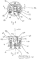
- the ion detector 20 is a combination channel electron multiplier/Faraday cup ion detector, such as the Continuous Dynode Electron Multiplier with Faraday Plate Model 366, manufactured by Detection Technology, Inc.
- the ion detector 20 includes a base portion 44 connected to a horizontal mounting plate 46, the detector having a center axis 57 which is coaxially aligned with the exit face of the ion analyzer 18, Fig. 1.
- the description which follows refers to the center axis 57 as being vertical. This description should not be interpreted as limiting, but is intended to provide a suitable frame of reference when comparing to the accompanying drawings.
- a Faraday collector (FC) 50 includes a three sided member having an open end 51, the three sides vertically extending in a direction which is parallel to the center axis 57 and spaced therefrom to define an open-ended rectangular enclosure.
- the FC 50 is mechanically attached by conventional means to the mounting plate 46 and is made from a conductive plate material, such as stainless steel, and attached electrically via a signal lead 53 attached to a mounting screw 55 or other fastener supporting the base portion to the mounting plate, the signal lead extending to an electrometer 54 connecting the FC essentially to ground potential.
- a beveled plate portion 59 of the Faraday collector 50 extends inwardly from each of the sides thereof and is angled relative to the horizontal axis. In the present embodiment, the plate portion is angled approximately 45 degrees, though this value can be varied.
- the beveled plate portion 59 is spotwelded or otherwise integrally formed with the remainder of the collector 50.
- a tubularly shaped continuous dynode electron multiplier 58 having a thermally conductive interior surface on an insulating substrate includes a conically shaped entrance opening 62 having a conductive grid shield 61, Fig. 2, which is connected by known means to a power supply (not shown), the conical opening facing the open end 51 of the FC 50.
- the electron multiplier 58 includes a hollow interior and axially extends in a horizontal plane through a substantially 360 degree circuit, the multiplier having an exit end opening 63 disposed in proximity with a vertically extending grounded shield 60 with an appropriately sized hole 56 for electrons to strike the extenor side of the Faraday collector 50.
- the multiplier 58 is supported mechanically with clips 65 connected to respective EM voltage sources 69.
- the exit end opening 63 is substantially diametrically opposite from the conical entrance opening 62.
- Each of the FC 50, the electron multiplier 58 are housed within a cylindrical grounded shield 71, as is known.
- the operation of the ion detector 20 is as follows: First, and in the FC mode of operation, the FC is connected to the input of the electrometer 54, which is essentially at ground potential.
- the incoming ion beam enters the ion detector 20 along the center axis 57 and impinges upon the beveled plate 59.
- the ions are positively charged, as noted above, and are neutralized upon striking the beveled plate 59, drawing current as a signal output to the electrometer 54.
- the problem, as described above, are that photons and other energetic uncharged particles from the total pressure collector 22, Fig. 1, are also transmitted through the ion analyzer along the direction of travel of the ion beam.
- a high voltage electrical potential is established (approximately -1000 to -3000 volts, -1150 volts according to this embodiment) at the grid shield 61 adjacent the conical entrance opening 62.
- This negative potential draws the positive ions from the incoming beam into the interior of the multiplier where secondary electrons are created.
- a less negative potential (approximately -650 volts according to this embodiment) further accelerates the electrons to the exit end opening 63 where the negative potential repels the electrons through the exit end opening through the hole in the grounded shield and toward the exterior side of the FC 50.
- Electrons emerging from the opposing exit end opening 63 of the multiplier 58 located substantially diametrically opposite to the conical entrance opening 62 are caused to impinge against the proximate exterior side of the FC 50. Further details relating to the theory of electron amplification are described in greater detail in U.S. Patent No. 4,227,087, the entire contents of which are incorporated herein by reference.
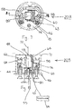
- a preferred ion detector 20A is now described for use with the foregoing mass spectrometer. For the sake of clarity, similar parts are labeled with the same reference numerals.
- a mass spectrometer 1A is shown having an ion source 16, a total pressure ion collector 22 and an ion analyzer 18, such as a quadrupole mass filter, arranged in the manner previously described.
- an ion analyzer 18 such as a quadrupole mass filter
- the ion detector 20A includes a base portion 44 attached to a horizontal mounting plate 46, and includes a center axis 57, similarly aligned with the direction of travel of an incoming ion beam.
- the interior of the detector 20A includes a cylindrical grounded shield 71 surrounding the active components of the detector and an interior shield 60 includes a hole 56 through which electrons from the EM impinge onto the exterior side of the FC 78
- the ion detector 20A also includes an electron multiplier 58, preferably made from a dynode material, which is disposed in the manner previously described and having a conical entrance opening 48.
- the multiplier 58 extends axially in a substantially circular manner and includes an exit end opening 63 diametrically opposite from the conical entrance opening 62 relative to thc center axis 57.
- the plane of the entrance and exit ends 62, 63 are substantially vertical and are spaced from the center axis 57 of the ion detector 20A.
- a conductive grid shield 61 covers the conical entrance opening 62 and acts an electrode such that a negative high voltage potential can be applied for diverting the positive ions from the incoming ion beam.
- the electron multiplier 58 is electrically connected to an electrometer 54.
- the electrometer 54 is of the bi-polar type for reasons detailed below.
- the ion detector 20A also includes a Faraday collector (FC) 78 defined by a rectangularly shaped enclosure defined by three orthogonal and vertically extending sides and an open end disposed about the center axis 57 of the ion detector 20A and mounted by conventional means.
- FC Faraday collector
- FC 78 no horizontal or beveled plate portion is provided, meaning that no portion of the FC 78 is in the path of the incoming ion beam.
- a beam shield 80 made from a suitable conductive material, is attached and connected by known means to ground potential.
- the beam shield 80 is a flat conductive plate member extending substantially horizontal; that is, substantially parallel to the mounting plate 46, the shield being roughly centered on the center axis 57 of the ion detector 20A and beneath the electron multiplier 58 and the FC 78. In this configuration, the beam shield 80 is aligned with the exit lens (not shown) of the ion analyzer 18.
- the ion detector 20A is capable of selective modes of operation, employing either an FC mode or an EM mode.
- a positive electrical potential is applied to the grid shield 61 at the conical opening 62 of the electron multiplier 58. It has been determined that a potential of between 50 and 100 volts is suitable. Approximately, 50 volts are applied in the present embodiment.
- the positive ions passing emerging from the ion analyzer 18 from the ionization volume 26 are deflected due to the applied positive bias of the electric field, thereby repelling the ions to impinge upon the vertically disposed sides of the FC 78.
- the EM mode of operation of the present ion detector 20A is unchanged. That is, a high voltage negative potential is again established (approximately -1.15kv) at the entrance grid shield 61 ofthe electron multiplier 58 causing the incoming beam of positive ions to be deflected by the created electric field to the conical opening 62. The ions are accelerated through the interior of the hollow dynode member, producing electrons through contacting the interior wall of the multiplier 58. The less negative potential at the exit end repels the formed electrons onto the exterior side of the conductive FC 78, which is electrically connected in a known manner to the electrometer 54.
- a single bi-polar electrometer can be utilized. Inversion of the polarity of the negative electron current from the EM detector output is accomplished with a gain of (-1) amplifier stage of the electrometer output to produce a positive ion intensity signal for each detection mode.
- any uncharged particles entering the ion detector 20A in this mode are unaffected by the generated electric field, and impinge directly upon the beam shield 80. Any electrons created as a result of the particles striking the surface of the beam shield 80 do not affect the output of current. Therefore, the overall positive baseline effect shown in Fig. 3(a) is minimized, improving the output characteristics of the mass spectrometer.
- single mode off-axis FC detectors can also be modified in accordance with the teachings of the present invention.
- a positive potential can be applied to a conductive plate or other shaped collector to deflect the incoming ion beam using a positive potential in the manner described for the EM grid.
- a grounded beam shield disposed in the path of the ion beam can be used to stop photons and neutral particles.
- this potential can be applied, for example, using the power source 24, Fig. 1, used to bias the anode 36, Figs. 2, 6.
Landscapes
- Chemical & Material Sciences (AREA)
- Analytical Chemistry (AREA)
- Electron Tubes For Measurement (AREA)
Applications Claiming Priority (6)
| Application Number | Priority Date | Filing Date | Title |
|---|---|---|---|
| US7212298P | 1998-01-22 | 1998-01-22 | |
| US72122 | 1998-01-22 | ||
| US8391898P | 1998-05-01 | 1998-05-01 | |
| US83918 | 1998-05-01 | ||
| US72034 | 1998-05-04 | ||
| US09/072,034 US6091068A (en) | 1998-05-04 | 1998-05-04 | Ion collector assembly |
Publications (2)
| Publication Number | Publication Date |
|---|---|
| EP0932184A1 true EP0932184A1 (de) | 1999-07-28 |
| EP0932184B1 EP0932184B1 (de) | 2011-05-25 |
Family
ID=27372010
Family Applications (1)
| Application Number | Title | Priority Date | Filing Date |
|---|---|---|---|
| EP19990101152 Expired - Lifetime EP0932184B1 (de) | 1998-01-22 | 1999-01-21 | Ionendetektionsvorrichtung |
Country Status (1)
| Country | Link |
|---|---|
| EP (1) | EP0932184B1 (de) |
Cited By (3)
| Publication number | Priority date | Publication date | Assignee | Title |
|---|---|---|---|---|
| GB2393035A (en) * | 2002-08-16 | 2004-03-17 | Thermo Finnigan Mat Gmbh | Device for collecting ions in a mass spectrometer |
| EP1533828A1 (de) * | 2003-11-21 | 2005-05-25 | GV Instruments Limited | Iondetektor |
| CN102426173A (zh) * | 2011-10-20 | 2012-04-25 | 中国航天科技集团公司第五研究院第五一〇研究所 | 一种弱电子束的测试装置及方法 |
Families Citing this family (2)
| Publication number | Priority date | Publication date | Assignee | Title |
|---|---|---|---|---|
| CN102928154B (zh) * | 2012-11-27 | 2014-05-28 | 中国航天科技集团公司第五研究院第五一〇研究所 | 一种减小电子激励脱附中性粒子误差的极高真空测量方法 |
| JP6734449B1 (ja) * | 2019-08-02 | 2020-08-05 | 浜松ホトニクス株式会社 | イオン検出器、測定装置および質量分析装置 |
Citations (4)
| Publication number | Priority date | Publication date | Assignee | Title |
|---|---|---|---|---|
| US4227087A (en) * | 1979-05-18 | 1980-10-07 | Galileo Electro-Optics Corp. | Beam detector |
| US4234791A (en) * | 1978-11-13 | 1980-11-18 | Research Corporation | Tandem quadrupole mass spectrometer for selected ion fragmentation studies and low energy collision induced dissociator therefor |
| US4267448A (en) * | 1978-06-12 | 1981-05-12 | Varian Mat Gmbh | Ion detector with bipolar accelerating electrode |
| US4731538A (en) * | 1986-06-20 | 1988-03-15 | Galileo Electro-Optics Corp. | Microchannel plate ion detector |
-
1999
- 1999-01-21 EP EP19990101152 patent/EP0932184B1/de not_active Expired - Lifetime
Patent Citations (5)
| Publication number | Priority date | Publication date | Assignee | Title |
|---|---|---|---|---|
| US4267448A (en) * | 1978-06-12 | 1981-05-12 | Varian Mat Gmbh | Ion detector with bipolar accelerating electrode |
| US4267448B1 (de) * | 1978-06-12 | 1985-09-24 | ||
| US4234791A (en) * | 1978-11-13 | 1980-11-18 | Research Corporation | Tandem quadrupole mass spectrometer for selected ion fragmentation studies and low energy collision induced dissociator therefor |
| US4227087A (en) * | 1979-05-18 | 1980-10-07 | Galileo Electro-Optics Corp. | Beam detector |
| US4731538A (en) * | 1986-06-20 | 1988-03-15 | Galileo Electro-Optics Corp. | Microchannel plate ion detector |
Cited By (5)
| Publication number | Priority date | Publication date | Assignee | Title |
|---|---|---|---|---|
| GB2393035A (en) * | 2002-08-16 | 2004-03-17 | Thermo Finnigan Mat Gmbh | Device for collecting ions in a mass spectrometer |
| US6949737B2 (en) | 2002-08-16 | 2005-09-27 | Thermo Electron (Bremen) Gmbh | Device for collecting ions in a mass spectrometer |
| GB2393035B (en) * | 2002-08-16 | 2005-10-26 | Thermo Finnigan Mat Gmbh | Device for collecting ions |
| EP1533828A1 (de) * | 2003-11-21 | 2005-05-25 | GV Instruments Limited | Iondetektor |
| CN102426173A (zh) * | 2011-10-20 | 2012-04-25 | 中国航天科技集团公司第五研究院第五一〇研究所 | 一种弱电子束的测试装置及方法 |
Also Published As
| Publication number | Publication date |
|---|---|
| EP0932184B1 (de) | 2011-05-25 |
Similar Documents
| Publication | Publication Date | Title |
|---|---|---|
| US6091068A (en) | Ion collector assembly | |
| US5202561A (en) | Device and method for analyzing ions of high mass | |
| US7550722B2 (en) | Focal plane detector assembly of a mass spectrometer | |
| Myers et al. | Preliminary design considerations and characteristics of an inductively coupled plasma-time-of-flight mass spectrometer | |
| US4058724A (en) | Ion Scattering spectrometer with two analyzers preferably in tandem | |
| US5223711A (en) | Plasma sources mass spectrometry | |
| JP3500323B2 (ja) | サイクロイド質量分析計に使用されるイオナイザー | |
| EP0559202B1 (de) | Sekundärionenmassenspektrometer zur Analyse positiv und negativ geladener Ionen | |
| US5665966A (en) | Current measuring system | |
| US5834770A (en) | Ion collecting electrode for total pressure collector | |
| EP0278034A1 (de) | Ladungsteilchendetektor | |
| US3939344A (en) | Prefilter-ionizer apparatus for use with quadrupole type secondary-ion mass spectrometers | |
| EP0932184B1 (de) | Ionendetektionsvorrichtung | |
| US2769911A (en) | Mass spectrometer for analysing substances or indicating a small amount of a determined substance | |
| US7220970B2 (en) | Process and device for measuring ions | |
| Cromwell et al. | Novel multichannel plasma-source mass spectrometer | |
| US20050109947A1 (en) | Ion detector | |
| US20240128070A1 (en) | Multimode ion detector with wide dynamic range and automatic mode switching | |
| CN210897194U (zh) | 一种用于飞行时间质谱仪的离子信号检测装置 | |
| US4137453A (en) | Methods and apparatus for improving electron capture detectors by collection of ions | |
| CN114730695A (zh) | 具有离子源的气体分析器系统 | |
| Evans | [3] Detectors | |
| US6642641B2 (en) | Apparatus for measuring total pressure and partial pressure with common electron beam | |
| CN112868085A (zh) | 离子检测器 | |
| JP2990321B2 (ja) | 誘導プラズマ質量分析装置 |
Legal Events
| Date | Code | Title | Description |
|---|---|---|---|
| PUAI | Public reference made under article 153(3) epc to a published international application that has entered the european phase |
Free format text: ORIGINAL CODE: 0009012 |
|
| AK | Designated contracting states |
Kind code of ref document: A1 Designated state(s): DE GB |
|
| AX | Request for extension of the european patent |
Free format text: AL;LT;LV;MK;RO;SI |
|
| 17P | Request for examination filed |
Effective date: 19991215 |
|
| AKX | Designation fees paid |
Free format text: DE GB |
|
| 17Q | First examination report despatched |
Effective date: 20021127 |
|
| GRAP | Despatch of communication of intention to grant a patent |
Free format text: ORIGINAL CODE: EPIDOSNIGR1 |
|
| GRAS | Grant fee paid |
Free format text: ORIGINAL CODE: EPIDOSNIGR3 |
|
| GRAA | (expected) grant |
Free format text: ORIGINAL CODE: 0009210 |
|
| AK | Designated contracting states |
Kind code of ref document: B1 Designated state(s): DE GB |
|
| REG | Reference to a national code |
Ref country code: GB Ref legal event code: FG4D |
|
| REG | Reference to a national code |
Ref country code: DE Ref legal event code: R096 Ref document number: 69943449 Country of ref document: DE Effective date: 20110707 |
|
| PLBE | No opposition filed within time limit |
Free format text: ORIGINAL CODE: 0009261 |
|
| STAA | Information on the status of an ep patent application or granted ep patent |
Free format text: STATUS: NO OPPOSITION FILED WITHIN TIME LIMIT |
|
| 26N | No opposition filed |
Effective date: 20120228 |
|
| REG | Reference to a national code |
Ref country code: DE Ref legal event code: R097 Ref document number: 69943449 Country of ref document: DE Effective date: 20120228 |
|
| PGFP | Annual fee paid to national office [announced via postgrant information from national office to epo] |
Ref country code: GB Payment date: 20180129 Year of fee payment: 20 Ref country code: DE Payment date: 20180129 Year of fee payment: 20 |
|
| REG | Reference to a national code |
Ref country code: DE Ref legal event code: R071 Ref document number: 69943449 Country of ref document: DE |
|
| REG | Reference to a national code |
Ref country code: GB Ref legal event code: PE20 Expiry date: 20190120 |
|
| PG25 | Lapsed in a contracting state [announced via postgrant information from national office to epo] |
Ref country code: GB Free format text: LAPSE BECAUSE OF EXPIRATION OF PROTECTION Effective date: 20190120 |