EP0932246A2 - Machine électrique tournante du type à aimants permanents - Google Patents
Machine électrique tournante du type à aimants permanents Download PDFInfo
- Publication number
- EP0932246A2 EP0932246A2 EP99300473A EP99300473A EP0932246A2 EP 0932246 A2 EP0932246 A2 EP 0932246A2 EP 99300473 A EP99300473 A EP 99300473A EP 99300473 A EP99300473 A EP 99300473A EP 0932246 A2 EP0932246 A2 EP 0932246A2
- Authority
- EP
- European Patent Office
- Prior art keywords
- stator
- permanent magnet
- rotating machine
- type electrical
- magnet type
- Prior art date
- Legal status (The legal status is an assumption and is not a legal conclusion. Google has not performed a legal analysis and makes no representation as to the accuracy of the status listed.)
- Withdrawn
Links
Images





Classifications
-
- H—ELECTRICITY
- H02—GENERATION; CONVERSION OR DISTRIBUTION OF ELECTRIC POWER
- H02K—DYNAMO-ELECTRIC MACHINES
- H02K1/00—Details of the magnetic circuit
- H02K1/06—Details of the magnetic circuit characterised by the shape, form or construction
- H02K1/12—Stationary parts of the magnetic circuit
- H02K1/20—Stationary parts of the magnetic circuit with channels or ducts for flow of cooling medium
-
- H—ELECTRICITY
- H02—GENERATION; CONVERSION OR DISTRIBUTION OF ELECTRIC POWER
- H02K—DYNAMO-ELECTRIC MACHINES
- H02K1/00—Details of the magnetic circuit
- H02K1/06—Details of the magnetic circuit characterised by the shape, form or construction
- H02K1/12—Stationary parts of the magnetic circuit
- H02K1/16—Stator cores with slots for windings
- H02K1/165—Shape, form or location of the slots
-
- H—ELECTRICITY
- H02—GENERATION; CONVERSION OR DISTRIBUTION OF ELECTRIC POWER
- H02K—DYNAMO-ELECTRIC MACHINES
- H02K21/00—Synchronous motors having permanent magnets; Synchronous generators having permanent magnets
- H02K21/12—Synchronous motors having permanent magnets; Synchronous generators having permanent magnets with stationary armatures and rotating magnets
- H02K21/14—Synchronous motors having permanent magnets; Synchronous generators having permanent magnets with stationary armatures and rotating magnets with magnets rotating within the armatures
-
- H—ELECTRICITY
- H02—GENERATION; CONVERSION OR DISTRIBUTION OF ELECTRIC POWER
- H02K—DYNAMO-ELECTRIC MACHINES
- H02K29/00—Motors or generators having non-mechanical commutating devices, e.g. discharge tubes or semiconductor devices
- H02K29/06—Motors or generators having non-mechanical commutating devices, e.g. discharge tubes or semiconductor devices with position sensing devices
- H02K29/12—Motors or generators having non-mechanical commutating devices, e.g. discharge tubes or semiconductor devices with position sensing devices using detecting coils using the machine windings as detecting coil
-
- H—ELECTRICITY
- H02—GENERATION; CONVERSION OR DISTRIBUTION OF ELECTRIC POWER
- H02K—DYNAMO-ELECTRIC MACHINES
- H02K9/00—Arrangements for cooling or ventilating
- H02K9/22—Arrangements for cooling or ventilating by solid heat conducting material embedded in, or arranged in contact with, the stator or rotor, e.g. heat bridges
- H02K9/225—Heat pipes
Definitions
- the present invention relates to permanent magnet type electrical rotating machines, and more particularly to permanent magnetic type electrical rotating machines in which the construction of the stators is improved in order to prevent reduction of the properties of the permanent magnets that are the rotors.
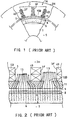
- FIG.1 is a partial cross-section view, in a direction orthogonal to the axis, showing an example of a prior art permanent magnet type electrical rotating machine.
- FIG.2 is an enlarged development view of part C of FIG.1.
- slots 3F are formed at equal intervals on the inner periphery of stator core 2H that is formed in a cylindrical shape by laying silicon steel punched plates one on another. Stator winding 4B is inserted into these slots 3F in two layers. Trapezoidal wedges 11, fabricated of magnetic material described later, are press-fitted into the inner periphery sides of slots 3F. Tooth-like parts 10B of the stator core are formed between slots 3F .
- Wedges 11 are made of hardened material by mixing malleable iron powder with resin and a reinforcing agent to become high-resistance magnetic material with a relative magnetic permeability ( ⁇ ) of about 10 ⁇ 100.
- permanent magnets 6 of arc-shaped cross-section are mounted in close contact with the outer periphery of rotor core 7 in the peripheral direction and bonded with an adhesive agent to form rotor 5 .
- Magnets magnetized with S poles on the inner periphery side and N poles on the outer periphery side are mounted alternately with magnets magnetized with the reverse polarity, according to the number of poles.
- magnetic flux 13 emanating from the outer periphery side of permanent magnets 6 reaches the outer periphery side of stator core 2H from wedges 11 and tooth-like parts 10B between these wedges 11 after passing through retaining ring 8 and gap 9, as shown in FIG.2. From this outer periphery side, the flux once more passes through a magnetic path via the neighbouring permanent magnet poles.
- This permanent magnetic type electrical rotating machine is driven in rotation at high speed by increasing the frequency of the inverter power source that excites stator winding 4B .
- FIG.3 is a drawing corresponding to FIG.2, and is an enlarged partial development illustration showing the magnetic flux distribution emanating from a permanent magnet for the case when non-magnetic wedges 12 are used in place of magnetic material wedges 11 .
- FIG.3 the point of difference from above-mentioned FIG.2 is that the greater part of magnetic flux 13 emanating from permanent magnets 6 passes through tooth-like parts 10B of stator core 2H while hardly any passes through non-magnetic wedges 12.
- one object of the present invention is to provide a novel permanent magnet type electrical rotating machine that may prevent the reduction in the permanent magnet properties consequent upon the temperature rise of the retaining ring, and may also solve the problem of wedge damage.
- a rotor in opposition to the inner part of a cylindrical stator, in which multiple enclosed slots that form projecting parts on the shaft center side of their stator winding insertion parts are formed radially at equal intervals, a rotor, on the outer periphery of which multiple permanent magnets with their polarities reversed in the radial direction are closely mounted, is inserted on the same shaft, and a cylindrical retaining ring is closely inserted on the outer periphery of this rotor.
- the stator winding is composed of U-shaped wire bundles of rectangular cross-section, and the open ends of the U-shapes are connected.
- the stator is divided into two at the shaft center side, or the outer periphery side, of the stator winding.
- the shapes of the inner periphery of the outer stator and the outer periphery of the inner stator of a stator that is divided into two at the outer periphery side of the stator winding are formed as ellipses.
- the shapes of the inner periphery of the outer stator and the outer periphery of the inner stator of a stator that is divided into two at the outer periphery side of the stator winding are formed as circles having straight line parts in at least one place.
- the shapes of the inner periphery of the outer stator and the outer periphery of the inner stator of a stator that is divided into two at the outer periphery side of the stator winding are formed in shapes from pentagons to polygons with the same number of angles as the number of stator coils.
- the heat intake sides of heat pipes are installed in the projecting parts formed in the above-mentioned enclosed slots of the stator.
- detector coils that detect the angle of rotation of the rotor are installed in the projecting parts formed in the enclosed slots of the stator.
- vibration suppression coils through which a current corresponding to the rotor vibration is passed and that suppress the vibration of the rotor, are installed in the projecting parts formed in the enclosed slots of the stator.
- non-magnetic rear wedges are installed in outer periphery sides of the slots of the inner stator that is divided into two at the outer periphery side of the stator winding.
- the permanent magnet type electrical rotating machine is made a super-high speed permanent magnet type electrical rotating machine.
- the retaining ring and the inner periphery of the stator are set in continual magnetic opposition one against the other.
- oscillation of the magnetic flux distribution in the peripheral direction between this retaining ring and the stator is prevented, oscillation of the torque caused by this oscillation and the temperature rise due to eddy currents in the retaining ring are suppressed, and reduction of the properties of the permanent magnets is prevented.
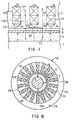
- FIG.5 is a longitudinal section view showing a first embodiment of the permanent magnet type electrical rotating machine of the present invention, and corresponds to the prior art technology shown in FIG.1.
- FIG.6(a) is an oblique view showing a stator winding that is assembled into the permanent magnet type electrical rotating machine shown in FIG.5, while FIG.6(b) is an enlargement of the cross-section view at B - B in FIG.5(a).
- FIG.7 is an enlarged development illustration of part A of FIG.5, and corresponds to the prior art technology shown in FIG.2 and FIG.3.
- FIG.5 and FIG.7 the points of difference from the prior art technology shown in FIG.1, FIG.2 and FIG.3 are that, in the construction of the stator, the slots formed in the stator core and the stator winding inserted into these slots are different.
- slots 3A punched radially in stator core 2A do not form openings on the inner periphery side of stator winding 4A , which is inserted into these slots 3A. They are enclosed slots in which triangular prism-shaped projecting parts are formed at the ends on the inner periphery side.
- stator windings 4A that are inserted in slots 3A are bent into U-shapes, as shown in FIG.6(a), and after laying wire strands 17 one upon another in a roughly square shape, as shown in FIG.6(b), outer skin insulation 18 is completed.
- stator windings 4A are inserted into each slot 3A of stator core 2A from one side in the axial direction. After connecting wires have been connected to the other ends by brazing, the connected parts are covered with insulating tape.
- neodium ⁇ iron ⁇ boron alloy (Nd-Fe-B alloy) is adopted for permanent magnets 6 on the outer periphery of rotor 5, and, in FIG.5, rotor 1A has two poles.
- wire bundles 18 of narrow wire strands 17 are used in stator winding 4A. Therefore, the increase of resistance value caused by the skin effect of high-frequency exciting currents due to high-speed rotation may be prevented, and temperature rise due to this may be inhibited.
- stator winding 4A which is the part with the highest temperature rise, may be cooled. Therefore deterioration of the insulation layer of stator winding 4A may be prevented, and its life may be extended. Thus, inspection and maintenance intervals may also be extended.
- torque oscillation may be prevented. Therefore, not only may speed adjustment times be shortened, but rotor vibration may be suppressed and bearing fatigue may also be prevented.
- the points of difference from FIG.5 showing the first embodiment described above are that the structure of the stator core is a two-division structure of a ring-shaped inner stator core and an outer stator core that is fitted outside this inner stator core. Apart from this, the remainder is the same as in the first embodiment shown in FIG.5 ⁇ FIG.7. Consequently, like reference numerals have been assigned to elements that are the same as in FIG.5 ⁇ FIG.7, and their descriptions have been omitted.
- stator core 2B shown in FIG.7 is composed of approximately ring-shaped inner stator core 2a, of which the outer periphery side of stator winding 4B is the outer periphery, and outer stator core 2b, which is fitted on the outer periphery of this inner stator core 2a.
- slots 3B, into which stator winding 4B is inserted, are open on the outer periphery side of inner stator core 2a, and stator winding 4B of the same configuration as the stator winding shown by the prior art technology of FIG.1 is fitted into them.
- outer stator core 2b on inner stator core 2a is by heating outer stator core 2b by induction heating and then fitting it on inner stator core 2a into which stator winding 4B has been inserted. When cooled to normal temperature, it is in a press-fitted state.
- stator winding 4B that has been produced with the same external shape as a prior art stator winding is incorporated.
- torque oscillation and the eddy currents generated in retaining ring 8 may also be reduced in the same way as with the first embodiment.
- FIG.9 is a longitudinal section view showing a third embodiment of a permanent magnet type electrical rotating machine of the present invention, and corresponds to FIG.5 and FIG.8 that show embodiments mentioned above.
- FIG.9 the point of difference from the embodiment shown in FIG.8 is that, while it has the same stator core structure and, like FIG.8, is divided into an inner stator core and an outer stator core, the configurations of those divided parts differ from FIG.8.
- stator 1C In a permanent magnet type electrical rotating machine in which stator 1C is composed in this way, by slightly heating outer stator core 2d , it may be fitted on inner stator core 2c. After cooling to normal temperature interlocking parts 2x bind closely together and, when running, the bonding strength of interlocking parts 2x further increases due to the heating of inner stator core 2c.
- FIG.10 is a longitudinal section view showing a fourth embodiment of a permanent magnet type electrical rotating machine of the present invention and corresponds to FIG.5, FIG.8 and FIG.9 that show embodiments mentioned above.
- FIG.10 the point of difference from the embodiments shown in FIG.8 and FIG.9 is that, although there is the same stator core structure, which is divided into an inner stator core and an outer stator core as in FIG.8 and FIG.9, the location of that division differs from FIG.8 and FIG.9.
- inner stator core 2e and outer stator core 2f of stator core 2D shown in FIG.10 are divided from each other at a position on the inner side face of stator winding 4A. Consequently, triangular prism-shaped gas passages for cooling are formed in the outer periphery side of inner stator core 2e .
- inner stator core 2e may be fitted by slightly heating outer stator core 2f. After cooling to normal temperature, the interlocked parts bind closely together and, when running, the bonding strength of the interlocked parts further increases due to the heating of inner stator core 2e.
- FIG.11 is a longitudinal section view showing a fifth embodiment of a permanent magnet type electrical rotating machine of the present invention, and corresponds to FIG.5 and FIG.8 ⁇ FIG.10 that show embodiments mentioned above.
- FIG.11 the point of difference from FIG.5, in which the above-mentioned first embodiment is shown, is that the heat-intake sides of heat pipes 14 that use Freon as the refrigerant, are inserted in the triangular prism-shaped parts of slots 3A of stator core 2A. The heat-release sides of these heat-pipes 14 are brazed to the outer frame of the stator.
- stator winding 4A In a permanent magnet type electrical rotating machine constructed in this way, the heat from the inner periphery side of stator winding 4A, which is the part with the highest temperature rise, is absorbed by the heat-intake sides of heat-pipes 14 .
- the refrigerant which has been gasified as a result, is condensed in the heat-release sides on the outer frame side and, after liquefaction, is caused to flow back to the heat-intake parts and cools stator winding 4A a second time. Thereafter, by repeating this, the insulating properties of the insulation layer of stator winding 4A, which determines the life and rated current of this electrical rotating machine, will be maintained.
- FIG.12 is a longitudinal section view showing a sixth embodiment of a permanent magnet type electrical rotating machine of the present invention, and corresponds to the above-mentioned FIG.5 and FIG.8 ⁇ FIG.11.
- FIG.12 the point of difference from FIG.11 is that auxiliary winding 15 is inserted into the projecting parts of slots 3A of stator core 2A, instead of heat pipes 14 shown an FIG.11. The remainder is the same as in FIG.11.
- This detection signal as inputted to separately-located inverter control device 22.
- a frequency is inputted to controlled inverter 23 by being ON/OFF controlled by the driving signal of inverter control device 22 .
- the electric power of the frequency outputted from inverter 23 controls the speed of rotation of the rotor by being supplied to stator winding 4A.
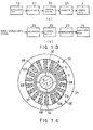
- FIG.13(b) is a block diagram showing a seventh embodiment of a permanent magnet type electrical rotating machine of the present invention, and corresponds to FIG.13(a).
- the detection signal of the rotor vibration that is generated by high-speed rotation is inputted to rotor displacement calculator 24 that calculates rotor displacement.
- the result of calculation by rotor displacement calculator 24 is inputted to inverter control device 22 and is amplified by amplifier 25 incorporated in inverter control device 22. After this, the amplified electric power excites auxiliary winding 15, and the vibration that causes shaft-deviation is suppressed by the electro-magnetic power of the magnetic flux generated by auxiliary winding 15.
- the rated maximum speed of rotation may be increased, and reduction of life due to vibration may be inhibited.
- FIG.14 An eighth embodiment of a permanent magnet type electrical rotating machine of the present invention will be described using FIG.14.
- FIG.14 differs from the above-mentioned second embodiment shown in FIG.8 is in the two-division structure of the rotor core. The remainder is the same as in the second embodiment shown in FIG.8. Consequently, like reference numerals have been assigned to elements that are the same as in FIG.8, and their descriptions have been omitted.
- stator core 2E shown in FIG.14 is composed of annular inner stator core 2g, of which the external diameters are, in the left to right direction a short diameter and in the front to back direction a long diameter, and outer stator core 2h, which is fitted to the outer periphery of inner stator core 2g.
- the reason for adopting this configuration is to prevent inner stator core 2g trying to turn under the turning force (torque) that is generated in inner stator core 2g as the rotor rotates.
- stator winding 4B is inserted in shallow slots 3B on the short diameter side and deep slots 3E on the long diameter side.
- Stator winding 4B of the same configuration as the stator winding shown in the prior art technology of FIG.1, is incorporated in the same way as in FIG.8.
- outer stator core 2h is heated by induction heating and then fitted to inner stator core 2g, into which stator winding 4B has been inserted.
- stator core 2g When it has been cooled to room temperature, the stator core is in a press-fitted state.
- stator winding 4B that has been produced with the same external shape as a prior art stator winding is incorporated.
- torque oscillation and the eddy currents generated in retaining ring 8 may also be reduced in the same way as with the first embodiment.
- FIG.15 is a longitudinal section view showing a ninth embodiment of a permanent magnet type electrical rotating machine of the present invention, and corresponds to FIG.5, FIG.8, FIG.9 and FIG.14 that show above-mentioned embodiments.
- stator core structure is similar and is divided into an inner stator core and an outer stator core in the same way as in FIG.14, the configurations of those divisions differ.
- stator core 2F shown in FIG.15 is composed of inner stator core 2j and outer stator core 2k. Parallel faces that fit closely together are formed in the outer periphery of inner stator core 2j and in the inner periphery of outer stator core 2k.
- non-magnetic rear wedges 16 are inserted into the slots formed in the outer periphery of inner stator core 2j.
- stator 1C In a permanent magnet type electrical rotating machine in which stator 1C is composed in this way, by slightly heating outer stator core 2k it may be fitted on inner stator core 2j and, after cooling to normal temperature, the interlocked parts will bind closely together. When running, the bonding strength of the interlocked parts further increases due to heating of inner stator core 2j.
- FIG.16 is a longitudinal section view showing a tenth embodiment of a permanent magnet type electrical rotating machine of the present invention, and corresponds to FIG.5, FIG.8, FIG.9, FIG.14 and FIG.15 showing above-mentioned embodiments.
- stator core structure is similar and is divided into an inner stator core and an outer stator core at the outer peripheries of the slots part in the same way as in FIG.9
- configuration of that division is, overall, a polygonal shape, being a series of short straight lines as opposed to the series of short arcs in FIG.9.
- stator core 2G shown in FIG.16 is composed by the interlocking of inner stator core 2m and outer stator core 2n, and also in FIG.16, there is a regular 18-angled polygon (octadecagon) with the same number of angles as there are stator windings 4B.
- stator 1J In a permanent magnet type electrical rotating machine in which stator 1J is constructed in this way, by slightly heating outer stator core 2n, inner stator core 2m may be inserted into it. After cooling to normal temperature, the interlocking parts will bind closely together. When running, the bonding strength of the interlocking parts will further increase due to heating of inner stator core 2m.
- heat pipes 14 shown in FIG.11 or the auxiliary coils shown in FIG.12 may also be inserted in the slots of the embodiments shown in FIG.15 ⁇ FIG.16.
- improvement in the cooling effect or further increase of speed through reducing inertia and vibration by shortening of the rotor may be designed.
- a rotor in which a plurality of permanent magnets with polarities alternately reversed in the radial direction are closely bonded to its outer periphery, is inserted on the same shaft as a tube-like stator, in which a plurality of enclosed slots that form projecting parts on the axial side of the stator coil insertion parts are formed radially at equal intervals.
- the influence of skin-effect during high-speed rotation is reduced by composing the stator coils by rectangular cross-section wire bundles of wire strands formed in U-shapes, and connecting the open ends of the U-shapes.
- incorporation of the stator winding is simplified by dividing the stator into two on the axial side or the outer periphery side of the stator winding, and continual magnetic opposition is set between the retaining ring and the inner periphery of the stator.
- the shapes of the inner periphery of the outer stator and the outer periphery of the inner stator, of the stator that is divided into two at the outer periphery of the stator winding are made elliptical. Furthermore, when using the present invention, assembly is simple and mutual slippage during rotation is prevented by making the shapes of the inner periphery of the outer stator and the outer periphery of the inner stator, of a stator that is divided into two at the outer periphery of the stator winding, circles provided with straight lines in at least one place.
- the heat-intake sides of heat pipes are inserted in the projecting parts formed in the enclosed slots of the stator, thus inhibiting any temperature rise of the stator winding.
- the shaft length of the rotor is decreased by inserting detector coils, that detect the angle of rotation of the rotor, into the projecting parts formed in the enclosed slots of the stator.
- vibration is suppressed by inserting vibration suppressor coils, that suppress vibration by passing currents corresponding to the vibration of the rotor, into the projecting parts formed in the enclosed slots of the stator.
- vibration suppressor coils that suppress vibration by passing currents corresponding to the vibration of the rotor
- the torque oscillation and retaining ring eddy currents caused by this magnetic oscillation are suppressed; and reduction of the permanent magnet properties is also prevented. Therefore it is possible to obtain a permanent magnet type electrical rotating machine that may prevent the reduction of the permanent magnet properties that accompanies temperature rise of the retaining ring, and may solve the problem of wedge damage.
- the stator coils are rendered operable by inserting non-magnetic rear wedges in the outer periphery sides of slots of the inner stator that is divided into two at the outer periphery of the stator winding.
- the stator coils are rendered operable by inserting non-magnetic rear wedges in the outer periphery sides of slots of the inner stator that is divided into two at the outer periphery of the stator winding.
- oscillation of the magnetic flux distribution in the periphery direction between this retaining ring and the rotor is prevented; the torque oscillation and retaining ring eddy currents caused by this magnetic oscillation are suppressed; and reduction of the permanent magnet properties is also prevented. Therefore it is possible to obtain a permanent magnet type electrical rotating machine that may prevent the reduction of the permanent magnet properties that accompanies temperature rise of the retaining ring, and may solve the problem of wedge damage.
Landscapes
- Engineering & Computer Science (AREA)
- Power Engineering (AREA)
- Iron Core Of Rotating Electric Machines (AREA)
- Permanent Magnet Type Synchronous Machine (AREA)
- Permanent Field Magnets Of Synchronous Machinery (AREA)
Applications Claiming Priority (2)
| Application Number | Priority Date | Filing Date | Title |
|---|---|---|---|
| JP1091498 | 1998-01-23 | ||
| JP10010914A JPH11215748A (ja) | 1998-01-23 | 1998-01-23 | 永久磁石形回転電機 |
Publications (2)
| Publication Number | Publication Date |
|---|---|
| EP0932246A2 true EP0932246A2 (fr) | 1999-07-28 |
| EP0932246A3 EP0932246A3 (fr) | 2000-11-08 |
Family
ID=11763543
Family Applications (1)
| Application Number | Title | Priority Date | Filing Date |
|---|---|---|---|
| EP99300473A Withdrawn EP0932246A3 (fr) | 1998-01-23 | 1999-01-22 | Machine électrique tournante du type à aimants permanents |
Country Status (4)
| Country | Link |
|---|---|
| US (1) | US6265801B1 (fr) |
| EP (1) | EP0932246A3 (fr) |
| JP (1) | JPH11215748A (fr) |
| CA (1) | CA2259794C (fr) |
Cited By (8)
| Publication number | Priority date | Publication date | Assignee | Title |
|---|---|---|---|---|
| EP1076402A3 (fr) * | 1999-08-11 | 2002-06-12 | Nihon Riken Co., Ltd. | Moteur électrique à aimants permanents |
| FR2819648A1 (fr) * | 2001-01-15 | 2002-07-19 | Renault | Stator et machine electrique synchrone a derivation limitee de flux |
| WO2004084378A1 (fr) * | 2003-03-21 | 2004-09-30 | Pratt & Whitney Canada Corp. | Moyen de limitation de courant pour un generateur |
| US6920023B2 (en) | 2003-03-21 | 2005-07-19 | Pratt & Whitney Canada Corp. | Current limiting means for a generator |
| US7253548B2 (en) | 2003-06-16 | 2007-08-07 | Pratt & Whitney Canada Corp. | Method and apparatus for controlling an electric machine |
| CN101917105A (zh) * | 2010-08-20 | 2010-12-15 | 哈尔滨东安发动机(集团)有限公司 | 一种高速永磁电机 |
| EP2451048A1 (fr) * | 2010-11-04 | 2012-05-09 | Siemens Aktiengesellschaft | Elément de bouchon magnétique pour fermer un canal d'un stator d'une génératrice |
| WO2012084590A1 (fr) * | 2010-12-23 | 2012-06-28 | Siemens Aktiengesellschaft | Palier radial magnétique pour le montage sur palier magnétique d'un rotor |
Families Citing this family (31)
| Publication number | Priority date | Publication date | Assignee | Title |
|---|---|---|---|---|
| US6489692B1 (en) * | 1999-12-13 | 2002-12-03 | Capstone Turbine Corporation | Method and apparatus for controlling rotation of magnetic rotor |
| EP1219007A4 (fr) * | 1999-12-14 | 2003-01-15 | Delphi Tech Inc | Moteur sans balai a rotor a faible inertie |
| JP3861593B2 (ja) * | 2000-12-11 | 2006-12-20 | 株式会社日立製作所 | リニアモータ |
| EP1468483A4 (fr) * | 2002-01-25 | 2008-02-27 | California Linear Devices Inc | Couche de surface portante pour moteur magnetique |
| US6983603B2 (en) * | 2002-10-24 | 2006-01-10 | Pratt & Whitney Canada Corp. | Detection of gas turbine engine hot section condition |
| US20040100154A1 (en) * | 2002-11-26 | 2004-05-27 | Rahman Khwaja M. | Concentrated winding electric motor having optimized winding cooling and slot fill |
| US6873071B2 (en) * | 2003-06-03 | 2005-03-29 | Pratt & Whitney Canada Corp. | Method, apparatus and system for controlling an electric machine |
| JP4563244B2 (ja) * | 2004-05-06 | 2010-10-13 | 有限会社 エルメック | 多相モータ |
| US20070138891A1 (en) * | 2005-12-19 | 2007-06-21 | Emerson Electric Co. | Magnet retention and positioning sleeve for surface mounted rotor assemblies |
| WO2008143492A1 (fr) * | 2007-05-24 | 2008-11-27 | Chris Reijmer | Dispositif de mouvement linéaire |
| DE102007033076A1 (de) * | 2007-07-13 | 2009-01-15 | Dr. Fritz Faulhaber Gmbh & Co. Kg | Elektrischer Kleinstantrieb sowie Rückschlusselement und Verfahren zu dessen Herstellung |
| US7851966B2 (en) * | 2008-01-10 | 2010-12-14 | Rippel Wally E | Stator for electric machine with improved efficiency and thermal performance |
| WO2010012070A1 (fr) * | 2008-07-28 | 2010-02-04 | Tm4 Inc. | Agencement de refroidissement liquide à trajets multiples pour machines électriques |
| EP2363699A1 (fr) * | 2010-03-02 | 2011-09-07 | Siemens Aktiengesellschaft | Surveillance des vibrations d'un élément magnétique dans une machine électrique |
| FI124814B (fi) * | 2010-10-18 | 2015-01-30 | Lappeenrannan Teknillinen Yliopisto | Sähkökoneen staattori ja sähkökone |
| JP5550525B2 (ja) | 2010-10-29 | 2014-07-16 | ビアメカニクス株式会社 | ガルバノスキャナ及びレーザ加工機 |
| JP5373759B2 (ja) * | 2010-12-28 | 2013-12-18 | トヨタ自動車株式会社 | 超電導モータ |
| FR3019947B1 (fr) * | 2014-04-10 | 2017-12-08 | Moteurs Leroy-Somer | Stator de machine electrique tournante. |
| FR3019948B1 (fr) | 2014-04-10 | 2017-12-22 | Moteurs Leroy-Somer | Rotor de machine electrique tournante. |
| US11255612B2 (en) | 2014-07-25 | 2022-02-22 | Enure, Inc. | Wound strip machine |
| CN106662408B (zh) | 2014-07-25 | 2019-11-05 | 普里派尔技术有限公司 | 流体冷却型卷绕式条带结构 |
| US10756583B2 (en) | 2014-07-25 | 2020-08-25 | Enure, Inc. | Wound strip machine |
| ES2711341T3 (es) * | 2016-05-13 | 2019-05-03 | Nidec Asi S P A | Motor eléctrico |
| JP7285620B2 (ja) * | 2017-10-31 | 2023-06-02 | ダイキン工業株式会社 | 電動機およびターボ圧縮機 |
| GB201718452D0 (en) * | 2017-11-08 | 2017-12-20 | Rolls Royce Plc | Permanent magnet electrical machine |
| US11296588B2 (en) | 2019-10-15 | 2022-04-05 | Darrell Schmidt Enterprises, Inc. | Magnetic coupler |
| US11522436B2 (en) | 2019-10-15 | 2022-12-06 | Darrell Schmidt Enterprises, Inc. | Permanently magnetized enhanced generator |
| JP6804700B1 (ja) * | 2020-01-21 | 2020-12-23 | 三菱電機株式会社 | 固定子およびこれを用いた回転電機 |
| EP4344026A4 (fr) * | 2021-10-09 | 2024-09-04 | Huawei Digital Power Technologies Co., Ltd. | Moteur synchrone à aimant permanent à flux variable, chaîne cinématique et ventilateur |
| US12278550B2 (en) * | 2022-03-09 | 2025-04-15 | GM Global Technology Operations LLC | Stator assembly of an electric motor with retrofitted heat pipes |
| WO2026028925A1 (fr) * | 2024-07-31 | 2026-02-05 | 日本製鉄株式会社 | Noyau de stator, machine électrique rotative et gabarit de pressurisation |
Family Cites Families (34)
| Publication number | Priority date | Publication date | Assignee | Title |
|---|---|---|---|---|
| US470217A (en) * | 1892-03-08 | Connection for armature-conductors | ||
| US2711008A (en) * | 1950-10-26 | 1955-06-21 | Beresford James & Son Ltd | Manufacture of stators for electric motors |
| US2763794A (en) * | 1951-09-28 | 1956-09-18 | Westinghouse Electric Corp | Turbine-generator ventilation |
| GB732783A (en) * | 1951-12-12 | 1955-06-29 | Vickers Electrical Co Ltd | Improvements relating to the construction of dynamo electric machines |
| US2781465A (en) * | 1955-03-15 | 1957-02-12 | Westinghouse Electric Corp | Rotor for electric motor |
| US3827141A (en) * | 1972-05-17 | 1974-08-06 | Skf Ind Trading & Dev | Method of manufacturing an electric rotary machine |
| US3980909A (en) * | 1972-08-01 | 1976-09-14 | The Black And Decker Manufacturing Company | Universal and D.C. motors with improved field structure for portable tools and appliances |
| DE2449090A1 (de) * | 1973-10-17 | 1975-04-30 | Hitachi Ltd | Stator einer rotierenden elektrischen maschine |
| CH582969A5 (fr) | 1975-03-12 | 1976-12-15 | Bbc Brown Boveri & Cie | |
| US4204314A (en) * | 1977-11-14 | 1980-05-27 | S.B.W. Engineers Limited | Method of making cast windings for electric motors |
| US4403401A (en) * | 1978-09-15 | 1983-09-13 | General Electric Company | Method of making a dynamoelectric machine stator having concentric amorphous metal laminations |
| JPS5790365U (fr) * | 1980-11-21 | 1982-06-03 | ||
| US4425521A (en) | 1982-06-03 | 1984-01-10 | General Electric Company | Magnetic slot wedge with low average permeability and high mechanical strength |
| JPH0824413B2 (ja) * | 1985-06-05 | 1996-03-06 | 株式会社日立製作所 | 永久磁石を有する回転子 |
| US4761576A (en) * | 1985-11-12 | 1988-08-02 | General Motors Corporation | Motor driven air moving apparatus for high speed, constant duty operation |
| US5233252A (en) * | 1985-11-20 | 1993-08-03 | Allied-Signal | Motor having integral detent |
| US4968911A (en) * | 1985-11-20 | 1990-11-06 | Allied-Signal Inc. | Clam-shell stator construction for electrical machines |
| DE3608472C2 (de) * | 1986-03-14 | 1994-04-07 | Bosch Gmbh Robert | Verfahren zur Geräuschminderung bei einer elektrischen Maschine und nach diesem Verfahren hergestellte elektrische Maschine, insbesondere Drehstromgenerator für Fahrzeuge |
| US4782260A (en) * | 1987-02-27 | 1988-11-01 | General Electric Company | Closed slot rotor construction |
| US4801832A (en) * | 1987-11-04 | 1989-01-31 | General Electric Company | Stator and rotor lamination construction for a dynamo-electric machine |
| US4864177A (en) * | 1987-12-16 | 1989-09-05 | Yang Tai Her | Stator lamination design for two-pole single-phase induction motor |
| JPH0295158A (ja) * | 1988-09-28 | 1990-04-05 | Fanuc Ltd | 可変リラクタンスタイプの交流サーボモータ |
| US5019735A (en) * | 1990-08-07 | 1991-05-28 | Lee Jen J | Motor construction for an electric fan |
| JPH06178466A (ja) * | 1992-12-04 | 1994-06-24 | Fujitsu General Ltd | コンデンサモータ |
| JPH06217476A (ja) * | 1993-01-13 | 1994-08-05 | Toshiba Corp | 回転電機の固定子 |
| US5349257A (en) * | 1993-04-06 | 1994-09-20 | Sundstrand Corporation | Permanent magnet generator with a position sensing coil |
| DE4322268A1 (de) * | 1993-07-05 | 1995-01-12 | Abb Management Ag | Horizontalachsige elektrische Maschine |
| JP2777331B2 (ja) * | 1994-05-20 | 1998-07-16 | 株式会社東芝 | 永久磁石形回転電機 |
| JPH08172742A (ja) | 1994-12-19 | 1996-07-02 | Toshiba Corp | 永久磁石界磁方式回転電機 |
| JP2782044B2 (ja) * | 1994-12-21 | 1998-07-30 | セイコー精機株式会社 | スピンドルモータ |
| JP3474660B2 (ja) * | 1995-01-23 | 2003-12-08 | 株式会社日立製作所 | 3相電動機 |
| US5698917A (en) * | 1995-09-25 | 1997-12-16 | Glacier Rpb Inc. | Electromagnetic bearing with a stationary armature canning arrangement |
| JP3256134B2 (ja) * | 1996-06-10 | 2002-02-12 | 松下電器産業株式会社 | 同期電動機の回転子位置検出装置 |
| US5821652A (en) * | 1996-08-28 | 1998-10-13 | Marathon Electric Manufacturing Corporation | Dynamoelectric machines with shaft voltage prevention method and structure |
-
1998
- 1998-01-23 JP JP10010914A patent/JPH11215748A/ja active Pending
-
1999
- 1999-01-21 CA CA002259794A patent/CA2259794C/fr not_active Expired - Fee Related
- 1999-01-22 US US09/235,480 patent/US6265801B1/en not_active Expired - Fee Related
- 1999-01-22 EP EP99300473A patent/EP0932246A3/fr not_active Withdrawn
Cited By (15)
| Publication number | Priority date | Publication date | Assignee | Title |
|---|---|---|---|---|
| EP1076402A3 (fr) * | 1999-08-11 | 2002-06-12 | Nihon Riken Co., Ltd. | Moteur électrique à aimants permanents |
| FR2819648A1 (fr) * | 2001-01-15 | 2002-07-19 | Renault | Stator et machine electrique synchrone a derivation limitee de flux |
| US7309939B2 (en) | 2003-03-21 | 2007-12-18 | Pratt & Whitney Canada Corp. | Current limiting means for a generator |
| US6920023B2 (en) | 2003-03-21 | 2005-07-19 | Pratt & Whitney Canada Corp. | Current limiting means for a generator |
| US7119467B2 (en) | 2003-03-21 | 2006-10-10 | Pratt & Whitney Canada Corp. | Current limiting means for a generator |
| WO2004084378A1 (fr) * | 2003-03-21 | 2004-09-30 | Pratt & Whitney Canada Corp. | Moyen de limitation de courant pour un generateur |
| US7436098B2 (en) | 2003-03-21 | 2008-10-14 | Pratt & Whitney Canada Corp. | Current limiting means for a generator |
| US7656067B2 (en) | 2003-03-21 | 2010-02-02 | Pratt & Whitney Canada Corp. | Current limiting means for a generator |
| US7253548B2 (en) | 2003-06-16 | 2007-08-07 | Pratt & Whitney Canada Corp. | Method and apparatus for controlling an electric machine |
| US7443070B2 (en) | 2003-06-16 | 2008-10-28 | Pratt & Whitney Canada Corp. | Method and apparatus for controlling an electric machine |
| CN101917105A (zh) * | 2010-08-20 | 2010-12-15 | 哈尔滨东安发动机(集团)有限公司 | 一种高速永磁电机 |
| EP2451048A1 (fr) * | 2010-11-04 | 2012-05-09 | Siemens Aktiengesellschaft | Elément de bouchon magnétique pour fermer un canal d'un stator d'une génératrice |
| US9356491B2 (en) | 2010-11-04 | 2016-05-31 | Siemens Aktiengesellschaft | Magnetic cap element for a stator of a generator |
| WO2012084590A1 (fr) * | 2010-12-23 | 2012-06-28 | Siemens Aktiengesellschaft | Palier radial magnétique pour le montage sur palier magnétique d'un rotor |
| US9634539B2 (en) | 2010-12-23 | 2017-04-25 | Siemens Aktiengesellschaft | Radial magnetic bearing for magnetic support of a rotor |
Also Published As
| Publication number | Publication date |
|---|---|
| JPH11215748A (ja) | 1999-08-06 |
| CA2259794C (fr) | 2008-04-15 |
| US6265801B1 (en) | 2001-07-24 |
| EP0932246A3 (fr) | 2000-11-08 |
| CA2259794A1 (fr) | 1999-07-23 |
Similar Documents
| Publication | Publication Date | Title |
|---|---|---|
| CA2259794C (fr) | Machine electrique tournante a aimant permanent | |
| AU2008209912B2 (en) | Ring motor | |
| EP2190103B1 (fr) | Machine tournante sans noyau de type à entrefer axial | |
| JP6903144B2 (ja) | 永久磁石式回転電機 | |
| US5723928A (en) | Induction motor and method of adjusting power factor of the same | |
| EP0823771B1 (fr) | Moteur | |
| KR101098459B1 (ko) | 초전도 코일 장치 및 유도자형 동기기(同期機) | |
| EP1286446A1 (fr) | Rotor et machine à aimants permanents | |
| US8110961B2 (en) | Permanent-magnet-less machine having an enclosed air gap | |
| US8390168B2 (en) | Permanent-magnet-less machine having an enclosed air gap | |
| JP3280896B2 (ja) | 永久磁石式リラクタンス型回転電機 | |
| JP5610989B2 (ja) | 回転電動機 | |
| CN102308460B (zh) | 电机 | |
| JP6615375B2 (ja) | 電動機および空気調和装置 | |
| JP3455002B2 (ja) | 永久磁石式回転電機 | |
| JP2011139617A (ja) | 回転電機 | |
| KR20010041091A (ko) | 영구 자석과 개선된 구조의 자기 저항체를 구비한 회전전기 기기 | |
| US7095153B1 (en) | Extended core for motor/generator | |
| US12341386B2 (en) | Manufacturing device for rotor and manufacturing method for rotor | |
| US20230216376A1 (en) | Electric motor | |
| CN117981205A (zh) | 转子的制造装置 | |
| JPH1028344A (ja) | 電動機 | |
| JP7660511B2 (ja) | 電動モータ | |
| JP2024177786A (ja) | 回転電機 | |
| JP2009065746A (ja) | キャンドモータ駆動システム |
Legal Events
| Date | Code | Title | Description |
|---|---|---|---|
| PUAI | Public reference made under article 153(3) epc to a published international application that has entered the european phase |
Free format text: ORIGINAL CODE: 0009012 |
|
| 17P | Request for examination filed |
Effective date: 19990212 |
|
| AK | Designated contracting states |
Kind code of ref document: A2 Designated state(s): AT CH DE FR GB IT LI SE |
|
| AX | Request for extension of the european patent |
Free format text: AL;LT;LV;MK;RO;SI |
|
| RIC1 | Information provided on ipc code assigned before grant |
Free format text: 7H 02K 21/14 A, 7H 02K 9/20 B, 7H 02K 1/16 B, 7H 02K 1/20 B, 7H 02K 29/12 B |
|
| PUAL | Search report despatched |
Free format text: ORIGINAL CODE: 0009013 |
|
| AK | Designated contracting states |
Kind code of ref document: A3 Designated state(s): AT BE CH CY DE DK ES FI FR GB GR IE IT LI LU MC NL PT SE |
|
| AX | Request for extension of the european patent |
Free format text: AL;LT;LV;MK;RO;SI |
|
| AKX | Designation fees paid |
Free format text: AT CH DE FR GB IT LI SE |
|
| 17Q | First examination report despatched |
Effective date: 20040622 |
|
| STAA | Information on the status of an ep patent application or granted ep patent |
Free format text: STATUS: THE APPLICATION IS DEEMED TO BE WITHDRAWN |
|
| 18D | Application deemed to be withdrawn |
Effective date: 20071204 |