EP0932323A2 - Verfahren zur Vermittlung von digitalen Sprachkanälen - Google Patents
Verfahren zur Vermittlung von digitalen Sprachkanälen Download PDFInfo
- Publication number
- EP0932323A2 EP0932323A2 EP99100518A EP99100518A EP0932323A2 EP 0932323 A2 EP0932323 A2 EP 0932323A2 EP 99100518 A EP99100518 A EP 99100518A EP 99100518 A EP99100518 A EP 99100518A EP 0932323 A2 EP0932323 A2 EP 0932323A2
- Authority
- EP
- European Patent Office
- Prior art keywords
- cfi
- time slots
- ports
- sub
- switching unit
- Prior art date
- Legal status (The legal status is an assumption and is not a legal conclusion. Google has not performed a legal analysis and makes no representation as to the accuracy of the status listed.)
- Withdrawn
Links
Images

Classifications
-
- H—ELECTRICITY
- H04—ELECTRIC COMMUNICATION TECHNIQUE
- H04Q—SELECTING
- H04Q11/00—Selecting arrangements for multiplex systems
- H04Q11/04—Selecting arrangements for multiplex systems for time-division multiplexing
- H04Q11/08—Time only switching
Definitions
- the present invention relates to a method for non-blocking switching of several digital Voice channels with a certain transmission rate in Time slots of a specified bit length are used a switching unit with a PCM (pulse code Modulation) interface and a CFI (Configurable Interface) interface, and with several PCM ports on the PCM interface and several CFI ports on the CFI interface, between PCM transmission lines connected to the PCM ports and connected to the CFI ports CFI transmission lines.
- the present invention also relates to a switching unit for implementation the conciliation procedure.
- Such a conciliation procedure has been over for some time known in the field of digital telephony.
- digital telephony In the digital telephony is in a first subscriber terminal an analog voice signal to be transmitted in certain Sampling intervals sampled and the samples digitized.
- the digitized samples are alone or alternately with the binary codes of others digitized signals via one line to a second Transfer subscriber terminal.
- the individual Binary codes are then assigned to the individual speech signals and reassembled into analog voice signals.
- the conversion of an analog voice signal into a digital signal in the first subscriber terminal is usually carried out by an A / D converter, which carries out the following steps in detail.
- a time-discrete sampling of the filtered speech signal takes place, for example using an electronic switch. It is important to ensure that the sampling frequency is at least twice the maximum frequency of the filtered speech signal.
- the samples of the still analog signal are digitized. With n-bit quantification, the amplitude of the signal between the amplitude maxima is divided, for example, into 2 n amplitude steps of the same size.
- n-bit binary code Since the transmission of the n-bit binary code is usually only needed a part of the sampling interval, with the help of a multiplexer several digitized n-bit binary codes of different speech signals in repetitive Cycles are transmitted sequentially over a line, i.e. in the remaining part of the sampling interval the Binary codes of other speech signals in one another following order can be transferred. Thereby results in a time-discrete pulse code modulation (PCM) multiplex signal, which via a line to the second Subscriber terminal is transmitted.
- PCM time-discrete pulse code modulation
- the binary codes are in the second subscriber terminal this PCM multiplex signal by a demultiplexer assigned to individual voice signals, and by a D / A converter become the binary codes of the individual speech signals reassembled into analog voice signals.
- the switching unit serves as voice signals Interface between different digital Transmission standards, in the present case as Interface between PCM transmission lines and CFI transmission lines.
- This Controller enables non-blocking switching of up to 64 digital voice channels with one transmission rate of 64 kbit / s.
- the voice channels are 8 bits long Transfer time slots in sampling intervals of 125 ⁇ s.
- this conversion unit has a PCM interface and a CFI interface.
- the CFI interface can be called IOM or be designed as an SLD interface. Except for mediation the controller also serves as an interface between the PCM transmission lines and the IOM or SLD transmission lines.
- the well-known "Extended PCM Interface Controller” can also digital voice channels with a lower transmission rate switch as 64 kbit / s, for example with 32 kbit / s or 16 kbit / s.
- the 8-bit time slots in the CFI interface instead of the full 8 bits like the one 64 kbit / s transfer rate only with sub-time slots with 4 bit length (at 32 kbit / s) or with 2 bit Length (at 16 kbit / s) occupied.
- At the individual CFI ports can be set which bits of the 8-bit time slots to be operated on the respective CFI port.
- So can for example with digital voice channels with a Transmission rate of 32 kbit / s either the upper or the lower 4 bits of an 8-bit time slot.
- the other 4 bits are free.
- the CFI ports will then be like this set that the upper or lower 4 bits of the 8-bit time slot to be served.
- the object of the present invention is therefore in a mediation process of the type mentioned to further develop that in the case of voice channels with a lower transmission rate corresponding to more voice channels can be conveyed without blocking.
- the invention proposes that Mediation of voice channels with a lower one Transmission rate in sub-time slots of a shorter bit length with the CFI interface with every time slot several sub-time slots assigned to the specified bit length be that by suitable devices every time slot with multiple sub-time slots in multiple time slots with a sub-time slot is divided and that one of the time slots each with a sub-time slot one of the CFI ports.
- each Time slot several sub-time slots of a shorter bit length be assigned to.
- each CFI port has a time slot of a specified bit length that only with a sub-time slot of a shorter bit length is occupied. So can be separately on each CFI port to which bit of the adjacent Timeslot to be accessed to the sub-timeslot to use. So only on the CFI ports Time slots with one sub-time slot each, each time slot is divided by several sub-time slots suitable devices in several time slots with each divided into a sub-time slot.
- the method according to the invention makes it efficient and non-blocking mediation of digital Allows voice channels with lower transmission rates. In particular, all available voice channels non-blocking and therefore fully usable.
- bit length of a time slot be a integer multiple of the bit length of a sub-time slot is. It follows that the particular Transmission rate, which is the bit length of the time slots corresponds to an integer multiple of the lower Transmission rate of the voice channel to be switched is.
- every time slot as many sub-time slots assigned that the sum of the bit lengths of the sub-time slots of a time slot equal to the bit length of the Time slot is. This will make the full bit length of the Time slots for the transmission of the voice channels with lower transmission rates and shorter bit lengths used.
- the voice channels in time slots one Length of 8 bits.
- the voice channels are then advantageously in sub-time slots with a length of 4 bits mediated or alternatively in sub-time slots one Length of 2 bits.
- one Time slot of a certain bit length different sub-time slots assigned with different bit lengths are. For example, it would be possible to use a time slot of 8 bits in length a sub-time slot of 4 bits in length and assign two sub-time slots of 2 bit length.
- the individual bits of the sub-time slots be arranged contiguously in the time slots.
- Another object of the present invention is in the efficiency of switching units of the beginning mentioned type in the mediation of voice channels to increase a lower transfer rate.
- the invention proposes that the switching unit each has as many CFI ports as sub-time slots are assigned to a time slot, to one CFI parallel port are interconnected in parallel.
- the CFI ports advantageously each have a data downstream line (Direction of transmission to the subscriber) and a data upstream line (direction of transmission to Switching unit), and each of the data downstream lines or the data upstream lines of the CFI ports are to the CFI parallel port with a data downstream parallel line and a data upstream parallel line interconnected.
- the switching unit time slots with a length of 8 Bit on.
- voice channels with a 64 kbit / s transmission rate in 8-bit time slots transfer.
- the switching unit is advantageous for switching up to 64 digital voice channels designed with a transmission rate of 32 kbit / s each. These voice channels are transmitted in sub-time slots of 4 bits in length, so that for an efficient Switching two sub-time slots to each time slot be assigned to. This allows the number of Voice channels by the invention Switching unit are conveyed without blocking can be doubled from 32 to 64.
- the top four bits of the time slots can be according to an advantageous development of the invention the CFI ports with an even number and the bottom four Bits of the time slots each with a via the CFI ports odd number can be operated.
- the switching unit is advantageously for the Switching of up to 128 digital voice channels with one Transmission rate of 16 kbit / s each.
- the These voice channels are transmitted in sub-time slots of 2 bits in length.
- the switching unit points typically time slots with a length of 8 bits, so that every time slot for efficient switching four sub-time slots are assigned. This allows the Number of voice channels by the invention Switching unit are conveyed without blocking can be quadrupled from 32 to 128.
- the mediating voice signals i.e. a length of the sub-time slots of 2 bits, and a length of the time slots of
- 8 bits are Invention four CFI ports each to a CFI parallel port connected in parallel with each other. This allows each four sub-time slots are assigned to one time slot.
- the CFI interface as IOM (ISDN Oriented Modular) interface is designed.
- IOM ISDN Oriented Modular
- subscriber terminals with a compressed transmission rate of 32 kbit / s each connected that work according to the DECT standard.
- the CFI interface is according to another one advantageous development of the invention as an SLD (Subscriber Line Data) interface.
- SLD Subscriber Line Data
- the switching unit or the procedure for a mixed operation with different Be designed bit rates contributes to universal usability at.
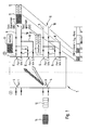
- the Switching unit 1 shows a switching unit according to the invention in in their entirety with the reference number 1.
- the Switching unit 1 has a PCM (Pulse Code Modulation) interface 2 and a CFI (Configurable Interface) interface 3 on.
- the CFI interface 3 is as IOM (ISDN Oriented Modular) interface designed, for example Subscriber terminals with a compressed transmission rate of 32 kbit / s each can be connected work according to the DECT standard.
- the switching unit points also several PCM ports 4 on the PCM interface 2 and several CFI ports 5 on the CFI interface 3.
- the CFI ports 5 each to a CFI parallel port 6 connected in parallel with each other. More specifically, the CFI ports 5 each have a data downstream line 7 (Direction of transmission to the subscriber) and a data upstream line 8 (direction of transmission to Switching unit), and each of the data downstream lines 7 or the data upstream lines 8 of two of the CFI ports 5 are to a CFI parallel port 6 with a data downstream parallel line 9 and a data upstream parallel line 10 interconnected.
- a data downstream line 7 Direction of transmission to the subscriber
- a data upstream line 8 direction of transmission to Switching unit
- Two voice channels 11 and 12 to be switched with one lower transmission rate, which is via the PCM interface 2 get to the switching unit 1 are by the Switching unit 1 to the CFI ports 5 with the names Port # 0 and Port # 1 conveyed to these to the Subscriber terminals (not shown) to arrive at the these CFI ports 5 (port # 0, port # 1) are connected.
- the time slots of the switching unit 1 for transmission of the voice channels are 8 bits long.
- the voice channels 11 and 12 do not need all 8 bits of the to transmit Time slots. They are in sub-time slots of 4 bits Transfer length.
- the 8-bit time slots are on CFI ports 5.
- On each CFI port 5 can be set to which bits access the respective CFI port 5 of the 8-bit time slots should. The setting can generally only be made per CFI port 5 respectively. For this reason, the 8-bit time slots are on each CFI port 5 has only one 4-bit sub-time slot assigned. In this way you can set 5 on the CFI ports whether a CFI port 5 on the top 4 bits of the time slot (like port # 0) or on the lower 4 bits of the time slot (how to access port # 1). Not with a sub-time slot occupied part of the time slot is inactive.
- port # 0 and Port # 1 has a time slot at CFI parallel port 6, to which two sub-time slots are assigned. More specifically, are the top 4 bits of the time slot with the sub time slot of the first voice channel 11 occupied, whereas the lower 4 bits with the sub-time slot of the second Voice channel 12 are busy.
- the other 8-bit time slots as well the switching unit 1 each two 4-bit sub-time slots assigned. This can reduce the number of voice channels with a lower transmission rate, that of the switching unit 1 are conveyed without blocking can, significantly increased, in the present Embodiment doubled.
- the CFI ports have no restriction, for example only voice channels a first bit rate, e.g. 32 kbit / s voice signals, too convey. 64 kbit / s voice channels can still be used are conveyed and this even optionally via port # 0 or Port # 1 of two CFI ports 5 connected in parallel without Limitations.
- Fig. 2 shows possible.
- This Time slot 13 with the higher bit rate than the time slots 11 and 12 can either be via CFI port # 0, such as shown in Fig. 2, or also via port # 1 of two coupled Ports 5, i.e. here ports connected in parallel, for Participants are mediated; it's just for that too ensure that the equivalent time slot of port 5, the should not be used, remains inactive.
- This method also works if on the PCM interface 2 Switching unit 1 both 64 kbit / s and 32 kbit / s speech samples be sent. These can be independent from each other and without blocking using variant (2) or (1) to the corresponding end devices.
- the measures shown make it possible in particular newly developed modules for the connection of 32 kbit / s DECT base stations in production to a function test undergo by using standard 64 kbit / s (ISDN) telephone terminals are connected to the switching unit 1 and over the phone.
- switching units in different assembly variants are used to to either exclusively 64 kbit / s (ISDN) terminals or Operate 32 kbit / s terminals on it.
- the switching unit 1 can of course be more integrated and the switching unit shown in FIGS. 1 and 2 contain multiple times, with no restriction of different variants occurs. The only important thing is that CFI ports are connected in parallel to the to implement different variants.
Landscapes
- Engineering & Computer Science (AREA)
- Computer Networks & Wireless Communication (AREA)
- Time-Division Multiplex Systems (AREA)
- Use Of Switch Circuits For Exchanges And Methods Of Control Of Multiplex Exchanges (AREA)
Abstract
Description
Claims (23)
- Verfahren zur blockierungsfreien Vermittlung von mehreren digitalen Sprachkanälen mit einer bestimmten Übertragungsrate in Zeitschlitzen einer festgelegten Bit-Länge unter Einsatz einer Vermittlungseinheit (1) mit einem PCM (Puls Code Modulation)-Interface (2) und einem CFI (Configurable Interface)-Interface (3), und mit mehreren PCM-Ports (4) an dem PCM-Interface (2) und mehreren CFI-Ports (5) an dem CFI-Interface (3), zwischen an den PCM-Ports (4) angeschlossenen PCM-Übertragungsleitungen und an den CFI-Ports (5) angeschlossenen CFI-Übertragungsleitungen, dadurch gekennzeichnet, daß zur Vermittlung von Sprachkanälen (11, 12) mit einer niedrigeren Übertragungsrate in Sub-Zeitschlitzen einer geringeren Bit-Länge bei dem CFI-Interface (3) jedem Zeitschlitz mit festgelegter Bit-Länge mehrere Sub-Zeitschlitze zugewiesen werden, daß durch geeignete Vorrichtungen jeder Zeitschlitz mit mehreren Sub-Zeitschlitzen in mehrere Zeitschlitze mit jeweils einem Sub-Zeitschlitz aufgeteilt wird und daß jeweils einer der Zeitschlitze mit einem Sub-Zeitschlitz an einem der CFI-Ports (5) anliegt.
- Verfahren nach Anspruch 1, dadurch gekennzeichnet, daß die Bit-Länge eines Zeitschlitzes ein ganzzahliges Vielfaches der Bit-Länge eines Sub-Zeitschlitzes ist.
- Verfahren nach Anspruch 2, dadurch gekennzeichnet, daß jedem Zeitschlitz so viele Sub-Zeitschlitze zugewiesen werden, daß die Summe der Bit-Längen der Sub-Zeitschlitze eines Zeitschlitzes gleich der Bit-Länge des Zeitschlitzes ist.
- Verfahren nach einem der Ansprüche 1 bis 3, dadurch gekennzeichnet, daß die Sprachkanäle (11, 12) in Zeitschlitzen einer Länge von 8 Bit vermittelt werden.
- Verfahren nach einem der Ansprüche 1 bis 4, dadurch gekennzeichnet, daß die Sprachkanäle (11, 12) in Sub-Zeitschlitzen einer Länge von 4 Bit vermittelt werden.
- Verfahren nach einem der Ansprüche 1 bis 4, dadurch gekennzeichnet, daß die Sprachkanäle (11, 12) in Sub-Zeitschlitzen einer Länge von 2 Bit vermittelt werden.
- Verfahren nach einem der Ansprüche 1 bis 6, dadurch gekennzeichnet, daß die einzelnen Bits der Sub-Zeitschlitze zusammenhängend in den Zeitschlitzen angeordnet werden.
- Vermittlungseinheit (1) zur Durchführung des Vermittlungsverfahrens nach einem der Ansprüche 1 bis 7, dadurch gekennzeichnet, daß jeweils so viele CFI-Ports (5) wie Sub-Zeitschlitze einem Zeitschlitz zugewiesen sind, zu einem CFI-Parallelport (6) parallel miteinander verschaltet sind.
- Vermittlungseinheit (1) nach Anspruch 8, dadurch gekennzeichnet, daß die CFI-Ports (5) jeweils eine Data-Downstream-Leitung (7) (Übertragungsrichtung zum Teilnehmer) und eine Data-Upstream-Leitung (8) (Übertragungsrichtung zur Vermittlungseinheit) aufweisen und daß jeweils die Data-Downstream-Leitungen (7) bzw. die Data-Upstream-Leitungen (8) der CFI-Ports (5) zu dem CFI-Parallelport (6) mit einer Data-Downstream-Parallelleitung (9) und einer Data-Upstream-Parallelleitung (10) miteinander verschaltet sind.
- Vermittlungseinheit (1) nach Anspruch 8 oder 9, dadurch gekennzeichnet, daß sie Zeitschlitze mit einer Länge von 8 Bit aufweist.
- Vermittlungseinheit (1) nach einem der Ansprüche 8 bis 10, dadurch gekennzeichnet, daß sie für die Vermittlung von bis zu 64 digitalen Sprachkanälen (11, 12) mit einer Übertragungsrate von jeweils 32 kBit/s ausgelegt ist.
- Vermittlungseinheit (1) nach Anspruch 10 und 11, dadurch gekennzeichnet, daß jeweils zwei CFI-Ports (5) zu einem CFI-Parallelport (6) parallel miteinander verschaltet sind.
- Vermittlungseinheit (1) nach Anspruch 12, dadurch gekennzeichnet, daß die oberen vier Bits der Zeitschlitze jeweils über die CFI-Ports (5) mit einer geraden Nummer und die unteren vier Bits der Zeitschlitze jeweils über die CFI-Ports (5) mit einer ungeraden Nummer bedient werden.
- Vermittlungseinheit (1) nach Anspruch 12, dadurch gekennzeichnet, daß die oberen vier Bits der Zeitschlitze jeweils über die CFI-Ports (5) mit einer ungeraden Nummer und die unteren vier Bits der Zeitschlitze jeweils über die CFI-Ports (5) mit einer geraden Nummer bedient werden.
- Vermittlungseinheit (1) nach einem der Ansprüche 8 bis 10, dadurch gekennzeichnet, daß sie für die Vermittlung von bis zu 128 digitalen Sprachkanälen (11, 12) mit einer Übertragungsrate von jeweils 16 kBit/s ausgelegt ist.
- Vermittlungseinheit (1) nach Anspruch 10 und 15, dadurch gekennzeichnet, daß jeweils vier CFI-Ports (5) zu einem CFI-Parallelport (6) parallel miteinander verschaltet sind.
- Vermittlungseinheit (1) nach einem der Ansprüche 8 bis 16, dadurch gekennzeichnet, daß das CFI-Interface (3) als IOM (ISDN Oriented Modular)-Interface ausgelegt ist.
- Verfahren nach einem der Ansprüche 1 bis 7, dadurch gekennzeichnet, daß Sprachkanäle (11, 12; 13) unterschiedlicher Bitraten an einem gemeinsamen PCM-Port (4) angeliefert werden, daß Sprachkanäle mit einer ersten Bitrate (11, 12) zu einem von mindestens zwei miteinander gekoppelten, insbesondere parallelgeschalteten, CFI-Ports (5) übertragen werden und daß Sprachkanäle mit einer zweiten Bitrate (13) ebenfalls zu einem dieser gekoppelten CFI-Ports (5) übertragen werden, wobei sichergestellt wird, daß der äquivalente Zeitschlitz des jeweils nicht benutzten CFI-Ports (5) inaktiv bleibt.
- Verfahren nach Anspruch 18, dadurch gekennzeichnet, daß sowohl 64 kbit/s- als auch 32 kbit/s-Sprachkanalsignale über die gleiche Vermittlungseinheit (1) vermittelt werden.
- Verfahren nach Anspruch 18 oder 19, dadurch gekennzeichnet, daß die Sprachkanalsignale mit der jeweils höheren Bitrate (13) wahlweise über einen der miteinander gekoppelten CFI-Ports (5) vermittelt werden.
- Verfahren nach einem der Ansprüche 18 bis 20, dadurch gekennzeichnet, daß insbesondere zu einem Funktionstest von Vermittlungseinheiten (1) zur Übertragung von digitalen Sprachkanälen einer ersten Bitrate, insbesondere 32 kbit/s- Sprachsignalen von DECT-Basisstationen, Endgeräte für eine zweite Bitrate, insbesondere 64 kbit/s (ISDN)-Endgeräte, angeschlossen werden und über diese Endgeräte der Funktionstest vorgenommen wird.
- Verfahren nach einem der Ansprüche 18 bis 21, dadurch gekennzeichnet, daß Vermittlungseinheiten (1) in unterschiedlichen Bestückungsvarianten dazu benutzt werden, um entweder ausschließlich Endgeräte für eine erste Bitrate, insbesondere 64 kbit/s (ISDN)-Endgeräte, oder Endgeräte für eine zweite Bitrate, insbesondere 32 kbit/s-Endgeräte, daran zu betreiben.
- Verfahren nach einem der Ansprüche 18 bis 22, dadurch gekennzeichnet, daß ein Mischbetrieb von Endgeräten mit verschiedenen Bitraten an vorzugsweise nur einer Vermittlungseinheit (1) vorgesehen ist.
Applications Claiming Priority (2)
| Application Number | Priority Date | Filing Date | Title |
|---|---|---|---|
| DE19800994 | 1998-01-14 | ||
| DE1998100994 DE19800994A1 (de) | 1998-01-14 | 1998-01-14 | Verfahren zur Vermittlung von digitalen Sprachkanälen |
Publications (2)
| Publication Number | Publication Date |
|---|---|
| EP0932323A2 true EP0932323A2 (de) | 1999-07-28 |
| EP0932323A3 EP0932323A3 (de) | 2001-03-28 |
Family
ID=7854490
Family Applications (1)
| Application Number | Title | Priority Date | Filing Date |
|---|---|---|---|
| EP99100518A Withdrawn EP0932323A3 (de) | 1998-01-14 | 1999-01-13 | Verfahren zur Vermittlung von digitalen Sprachkanälen |
Country Status (2)
| Country | Link |
|---|---|
| EP (1) | EP0932323A3 (de) |
| DE (1) | DE19800994A1 (de) |
Family Cites Families (2)
| Publication number | Priority date | Publication date | Assignee | Title |
|---|---|---|---|---|
| DE4309848C2 (de) * | 1993-03-26 | 1997-06-12 | Siemens Ag | Kommunikationssystem zum Anschluß an eine Basisstation eines mehrzellularen, drahtlosen Fernsprechsystems |
| CA2158298A1 (en) * | 1994-09-22 | 1996-03-23 | Haim Guata | Digital speech communication system |
-
1998
- 1998-01-14 DE DE1998100994 patent/DE19800994A1/de not_active Withdrawn
-
1999
- 1999-01-13 EP EP99100518A patent/EP0932323A3/de not_active Withdrawn
Also Published As
| Publication number | Publication date |
|---|---|
| DE19800994A1 (de) | 1999-07-15 |
| EP0932323A3 (de) | 2001-03-28 |
Similar Documents
| Publication | Publication Date | Title |
|---|---|---|
| EP0617522A2 (de) | Kommunikationssystem zum Anschluss an eine Basisstation eines mehrzellularen, drahtlosen Fernsprechsystems | |
| DE2714368C3 (de) | Schaltungsanordnung zum Durchschalten von Datenwörtern unterschiedlicher Bitfolgefrequenz in Vielfachverbindungen | |
| DE2523398B2 (de) | Zeitmultiplex-Vermittlungs anordnung | |
| DE2729014C2 (de) | Schaltungsanordnung für ein mehrstufiges Zeitmultiplex-Raumvielfach-Koppelfeld | |
| DE4225240A1 (de) | Kommunikationssystem zum bilden von virtuellen netzen zwischen privaten kommunikationsanlagen | |
| DE2915488A1 (de) | Schaltungsanordnung zur steuerung der uebertragung von digital-signalen, insbesondere pcm-signalen, zwischen anschlusstellen eines zeitmultiplex-fernmeldenetzes, insbesondere pcm-zeitmultiplex-fernmeldenetzes | |
| DE1929636A1 (de) | Zeitmultiplex-Pulscodemodulations-Nachrichtenanlage | |
| DE2346984C3 (de) | ||
| DE1230091B (de) | Zeitmultiplex-Vermittlungsanordnung in Fernmeldeanlagen, insbesondere Fernsprechvermittlungsanlagen | |
| CH623440A5 (de) | ||
| DE4141725C2 (de) | Schaltungsanordnung zum Übertragen nachrichtentechnischer Signale | |
| EP0151433A1 (de) | Gerätekonfiguration im Teilnehmerbereich eines ISDN-Netzes | |
| DE19800994A1 (de) | Verfahren zur Vermittlung von digitalen Sprachkanälen | |
| EP0570749B1 (de) | Schaltungsanordnung zur Übertragung nachrichtentechnischer Signale | |
| DE3539039C2 (de) | ||
| DE4409669C2 (de) | Adapter für den Anschluß mindestens eines analogen Fernsprechendgerätes an ein digitales Telefonnetz | |
| EP0781023A2 (de) | Bidirektionaler Datenaustausch (Protokoll) zwischen einer TK-Anlage und einer Endeinrichtung | |
| EP0669743B1 (de) | Personalcomputer mit einer Verbindung zu einer Basisstation eines drahtlosen Fernsprechsystems | |
| DE2021344B2 (de) | Schaltungsanordnung zur durchschaltung von nachrichtensignalen insbesondere pcm signalen in zeitmultiplex vermittlungsstellen eines zeitmultiplex insbesondere pcm zeitmultiplex fernmeldenetzes | |
| DE2928398C2 (de) | Verfahren zur digitalen Übertragung von Analogisignalen | |
| EP0963134B1 (de) | Verfahren zur Übertragung von Nutzdaten in einem Dienste integrierenden digitalen Netz (ISDN) | |
| DE2021344C (de) | Schaltungsanordnung zur Durchschaltung von Nachrichtensignalen, insbesondere PCM-Signalen, in Zeitmultiplex-Vermittlungsstellen eines Zeitmultiplex-, insbesondere PCM-Zeitmultiplex-Fernmeldenetzes | |
| DE3708975A1 (de) | Schaltungsanordnung zur uebertragung nachrichtentechnischer signale | |
| EP1125388A2 (de) | Verfahren zum übertragen von informationssignalen im teilnehmeranschlussbereich | |
| DE29605535U1 (de) | Vorrichtung zur Mehrfachnutzung einer Übertragungsleitung |
Legal Events
| Date | Code | Title | Description |
|---|---|---|---|
| PUAI | Public reference made under article 153(3) epc to a published international application that has entered the european phase |
Free format text: ORIGINAL CODE: 0009012 |
|
| AK | Designated contracting states |
Kind code of ref document: A2 Designated state(s): AT BE CH DE ES FR GB IT LI NL |
|
| AX | Request for extension of the european patent |
Free format text: AL;LT;LV;MK;RO;SI |
|
| RAP1 | Party data changed (applicant data changed or rights of an application transferred) |
Owner name: TENOVIS GMBH & CO. KG |
|
| PUAL | Search report despatched |
Free format text: ORIGINAL CODE: 0009013 |
|
| AK | Designated contracting states |
Kind code of ref document: A3 Designated state(s): AT BE CH CY DE DK ES FI FR GB GR IE IT LI LU MC NL PT SE |
|
| AX | Request for extension of the european patent |
Free format text: AL;LT;LV;MK;RO;SI |
|
| 17P | Request for examination filed |
Effective date: 20010904 |
|
| AKX | Designation fees paid | ||
| REG | Reference to a national code |
Ref country code: DE Ref legal event code: 8566 |
|
| RBV | Designated contracting states (corrected) |
Designated state(s): AT BE CH DE ES FR GB IT LI NL |
|
| 17Q | First examination report despatched |
Effective date: 20060814 |
|
| STAA | Information on the status of an ep patent application or granted ep patent |
Free format text: STATUS: THE APPLICATION IS DEEMED TO BE WITHDRAWN |
|
| 18D | Application deemed to be withdrawn |
Effective date: 20061228 |