EP0932329A1 - Dispositif de fixation détachable d'un appareil d'enregistrement électronique - Google Patents
Dispositif de fixation détachable d'un appareil d'enregistrement électronique Download PDFInfo
- Publication number
- EP0932329A1 EP0932329A1 EP99100466A EP99100466A EP0932329A1 EP 0932329 A1 EP0932329 A1 EP 0932329A1 EP 99100466 A EP99100466 A EP 99100466A EP 99100466 A EP99100466 A EP 99100466A EP 0932329 A1 EP0932329 A1 EP 0932329A1
- Authority
- EP
- European Patent Office
- Prior art keywords
- mounting plate
- registration device
- arrangement according
- housing
- bayonet
- Prior art date
- Legal status (The legal status is an assumption and is not a legal conclusion. Google has not performed a legal analysis and makes no representation as to the accuracy of the status listed.)
- Withdrawn
Links
Images


Classifications
-
- G—PHYSICS
- G01—MEASURING; TESTING
- G01P—MEASURING LINEAR OR ANGULAR SPEED, ACCELERATION, DECELERATION, OR SHOCK; INDICATING PRESENCE, ABSENCE, OR DIRECTION, OF MOVEMENT
- G01P1/00—Details of instruments
- G01P1/02—Housings
-
- G—PHYSICS
- G01—MEASURING; TESTING
- G01P—MEASURING LINEAR OR ANGULAR SPEED, ACCELERATION, DECELERATION, OR SHOCK; INDICATING PRESENCE, ABSENCE, OR DIRECTION, OF MOVEMENT
- G01P1/00—Details of instruments
- G01P1/12—Recording devices
- G01P1/127—Recording devices for acceleration values
-
- H—ELECTRICITY
- H05—ELECTRIC TECHNIQUES NOT OTHERWISE PROVIDED FOR
- H05K—PRINTED CIRCUITS; CASINGS OR CONSTRUCTIONAL DETAILS OF ELECTRIC APPARATUS; MANUFACTURE OF ASSEMBLAGES OF ELECTRICAL COMPONENTS
- H05K5/00—Casings, cabinets or drawers for electric apparatus
- H05K5/02—Details
- H05K5/0204—Mounting supporting structures on the outside of casings
Definitions
- the invention relates to an arrangement for releasably attaching a cuboid, electronic recording device by means of a mounting plate as well as on the mounting plate and on the registration device Coupling agents.
- the generic registration device is one accident data memory used in motor vehicles, for example this because of the shock-sensing acceleration sensors in the affected vehicle essentially horizontally and in one if possible Install the crush-proof area of the vehicle.
- EP 532 854 B1 a fastening device for a Known recording device of the type mentioned, which provides that on the Recording device a carrier and a holder are fixed at the installation location.
- Carrier and holder represent stable sheet metal parts, which are connected by means of tongue and slot connections in a plane parallel to the bottom of the case assembled and in the joining direction by means of a screw-slot nut connection are screwed together.
- the solution is disadvantageous in that the joining of the carrier and Holder requires a relatively sensitive assembly and the The screw connection provided at the installation site is usually poor is manageable and often only made from a certain direction can be. Understandably when removing the device, especially in a panic situation after an accident, resolving one Screw connection particularly unfavorable.
- the tongue-and-groove connections between carrier and holder as wedge connections are trained to be a backlash-free and even with unfavorable tolerance levels thus enable vibration-proof connection for vehicle use.
- the means that such a wedge connection often only when removing the device can still be solved using a tool, the installation location However, handling of a tool is considerably restricted. Furthermore, the Production of the stamped and bent parts intended for the holder and the carrier relatively complex.
- the object of the present invention was therefore the assembly to improve the registration device described, in particular the expansion to facilitate the registration device so that it is tool-free and can be done with one hand if necessary
- the aim of the invention is also the effort for the assembly reduce the necessary funds and a suitable for series production To create execution.
- the arrangement found solves the task and also offers the advantage that due to the special design of the bayonet connection means, the registration device related to the mounting plate in different Positions can be attached.
- the training of Housing of the recording device such that the bayonet element opposite walls of the housing can be fastened, the possibility to turn the housing at the installation site. That means the installation position of the The registration device is versatile with eight different positions variable, so that at the installation site an optimal accessibility for the with the Registration device to be connected can be found.
- the bayonet connection no additional Fasteners required and that only one screw for the central and rotation-proof attachment of the bayonet to the preferably square housing of the recording device is required.
- FIG. 1 shows, one is off, for example two shells 1 and 2 built housing an electronic Registration device 3 assigned a bayonet 4, which under Intermediate layer of a disc 5 by means of a screw 6 on the housing 1, 2 is attached.
- the screw 6 is in the hub 7 of the bayonet element 4 sunk.
- the hub 7 has on the in Figure 1 shown side has a cylindrical shape and serves as a centering pin in cooperation with a bore 8 which, for example, in a Vehicle floor 9 attached mounting plate 10 is formed.
- the Attachment of the mounting plate 10 is carried out using for example, three inserted in the vehicle floor 9 and more suitable Way sealed blind rivet nuts, two of which in Figures 1 and 5 - 11 and 12 - are shown as well as these associated screws 13 and 14, which are preferably toothed washers 15 and 16 underlaid.
- At 17 is a collar assigned to the plug base of the recording device 3 designated;
- Also indicated in FIG. 1 are a recording device 3 after its assembly on the mounting plate 10, connector 18 to be connected and a cable 19 terminated by the connector 18 Montage should be emphasized that only one, the arrow combination P Corresponding bayonet-like assembly movement of the registration device 3 is required. This is to enable assembly with one hand a convenient dimensioning of the recording device 3 useful.
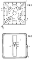
- the top view of the mounting plate 10, Figure 2 shows that the mounting plate 10 is stiffened with a peripheral edge 20 and a variety of Elongated holes - one is designated 21 - has to the To be able to set fasteners relatively variably, in particular Installation locations where there is little scope for arrangement for the device itself consists.
- the edge 20 is saved several times, the cuts 22 are from Ribs 23 and 24 flanked.
- Figure 2 also shows that in the Mounting plate 10 openings 25, 26, 27 and 28 provided and through Forming reinforcements 29, 30, 31 and 32 undercuts, of which in Figure 1 two 33 and 34 are visible, are formed.
- the steering element 4 has four resilient arms 35, 36, 37 and 38, the ends of which are bent so that they are in the openings 25, 26, 27, 28th can intervene and steerable behind the reinforcements 29, 30, 31, 32 are. Molded facets, one of which is designated 39, serve the purpose Sliding into the undercuts 33, 34.
- Figure 4 also shows that the hub 7 of the steering element 4 on the side assigned to the registration device 3 is provided with a square 40. At 41 is one of the screw 6 assigned assigned through hole.
- the square 40 is used positive connection with the housing 1, 2, that is, with a each formed in the shells 1 and 2 recess or shallow groove 42, the width of which corresponds to the side length of the square 40.
- a screw hole associated with the screw 6 designated.
- 44 denotes a lead frame, 45 a lead seal, one the two shells 1 and 2 of the housing 1, 2 connecting screw assigned. Since the groove 42 and the threaded hole 43 in each Shell 1 or 2 of the housing 1, 2 are formed, depending on the Installation conditions, the housing 1 2 can still be turned at the installation site. In each case a defined support of the housing 1, 2 on the mounting plate To achieve 10 feet are formed on both shells, one of which with 46 is designated. In connection with FIG.
- the locking member 47 has a long one Leg 48 on, when it is between the mounting plate 10 and the registration device 3 is set, a support on the registration device 3, and on a support surface 49 formed by a plurality of ribs.
- a tongue 50 which of Fingers 51 and 52 is flanked, formed.
- fingers 51 and 52 are unspecified Lugs formed so that the locking member can be mounted self-locking can, depending on the position of the registration device 3 on the Mounting plate 10 in one of the recesses 22 in the mounting plate 10 is inserted.
- the fingers 51, 52 engage behind the Ribs 23, 24 laterally, on the other hand overlaps those on the tongue 50 molded catch the peripheral edge 20.
Landscapes
- Physics & Mathematics (AREA)
- General Physics & Mathematics (AREA)
- Engineering & Computer Science (AREA)
- Microelectronics & Electronic Packaging (AREA)
- Connection Of Plates (AREA)
- Mounting Components In General For Electric Apparatus (AREA)
- Fittings On The Vehicle Exterior For Carrying Loads, And Devices For Holding Or Mounting Articles (AREA)
- Printers Or Recording Devices Using Electromagnetic And Radiation Means (AREA)
- Electrochromic Elements, Electrophoresis, Or Variable Reflection Or Absorption Elements (AREA)
- Mechanical Pencils And Projecting And Retracting Systems Therefor, And Multi-System Writing Instruments (AREA)
Applications Claiming Priority (2)
| Application Number | Priority Date | Filing Date | Title |
|---|---|---|---|
| DE29801003U | 1998-01-22 | ||
| DE29801003U DE29801003U1 (de) | 1998-01-22 | 1998-01-22 | Anordnung zum lösbaren Befestigen eines quaderförmigen, elektronischen Registriergerätes |
Publications (1)
| Publication Number | Publication Date |
|---|---|
| EP0932329A1 true EP0932329A1 (fr) | 1999-07-28 |
Family
ID=8051571
Family Applications (1)
| Application Number | Title | Priority Date | Filing Date |
|---|---|---|---|
| EP99100466A Withdrawn EP0932329A1 (fr) | 1998-01-22 | 1999-01-12 | Dispositif de fixation détachable d'un appareil d'enregistrement électronique |
Country Status (3)
| Country | Link |
|---|---|
| EP (1) | EP0932329A1 (fr) |
| JP (1) | JP4184519B2 (fr) |
| DE (1) | DE29801003U1 (fr) |
Cited By (2)
| Publication number | Priority date | Publication date | Assignee | Title |
|---|---|---|---|---|
| DE102008029950B4 (de) * | 2008-06-26 | 2015-07-23 | Günter Troska | Gehäuse |
| WO2021096532A1 (fr) * | 2019-11-15 | 2021-05-20 | Hewlett-Packard Development Company, L.P. | Supports de dispositif informatique dotés d'éléments d'espacement amovibles |
Families Citing this family (2)
| Publication number | Priority date | Publication date | Assignee | Title |
|---|---|---|---|---|
| DE4314190B4 (de) * | 1992-06-27 | 2007-03-15 | Siemens Ag | Zeigerinstrument |
| DE102011005113B4 (de) * | 2011-03-04 | 2026-05-07 | Zf Friedrichshafen Ag | Sensorträger-Abdeckungselement mit einer von außen erreichbaren Ausnehmung für ein Befestigungsmittel, Gehäuse für einen Sensor, Sensormodul und Verfahren zum Zusammenfügen eines Sensormoduls |
Citations (4)
| Publication number | Priority date | Publication date | Assignee | Title |
|---|---|---|---|---|
| GB1391941A (en) * | 1971-04-15 | 1975-04-23 | Sprecher & Schuh Ag | Electric modules |
| DE3108683A1 (de) * | 1981-03-07 | 1982-09-23 | Friedrich Lütze GmbH & Co, 7056 Weinstadt | Gehaeuse fuer ein loeschglied o. dgl. |
| DE3618685A1 (de) * | 1986-06-03 | 1987-12-10 | Paul & Siedler Gmbh & Co Kg | Elektrotechnisches bauelement |
| WO1994019727A1 (fr) * | 1993-02-23 | 1994-09-01 | Helmut Theodor Greiner | Dispositif de fixation d'un systeme de mesure sur une poignee |
-
1998
- 1998-01-22 DE DE29801003U patent/DE29801003U1/de not_active Expired - Lifetime
-
1999
- 1999-01-12 EP EP99100466A patent/EP0932329A1/fr not_active Withdrawn
- 1999-01-19 JP JP01040399A patent/JP4184519B2/ja not_active Expired - Fee Related
Patent Citations (4)
| Publication number | Priority date | Publication date | Assignee | Title |
|---|---|---|---|---|
| GB1391941A (en) * | 1971-04-15 | 1975-04-23 | Sprecher & Schuh Ag | Electric modules |
| DE3108683A1 (de) * | 1981-03-07 | 1982-09-23 | Friedrich Lütze GmbH & Co, 7056 Weinstadt | Gehaeuse fuer ein loeschglied o. dgl. |
| DE3618685A1 (de) * | 1986-06-03 | 1987-12-10 | Paul & Siedler Gmbh & Co Kg | Elektrotechnisches bauelement |
| WO1994019727A1 (fr) * | 1993-02-23 | 1994-09-01 | Helmut Theodor Greiner | Dispositif de fixation d'un systeme de mesure sur une poignee |
Cited By (3)
| Publication number | Priority date | Publication date | Assignee | Title |
|---|---|---|---|---|
| DE102008029950B4 (de) * | 2008-06-26 | 2015-07-23 | Günter Troska | Gehäuse |
| WO2021096532A1 (fr) * | 2019-11-15 | 2021-05-20 | Hewlett-Packard Development Company, L.P. | Supports de dispositif informatique dotés d'éléments d'espacement amovibles |
| US20220382341A1 (en) * | 2019-11-15 | 2022-12-01 | Hewlett-Packard Development Company, L.P. | Computing device mounts with removable spacers |
Also Published As
| Publication number | Publication date |
|---|---|
| JPH11284371A (ja) | 1999-10-15 |
| JP4184519B2 (ja) | 2008-11-19 |
| DE29801003U1 (de) | 1998-03-19 |
Similar Documents
| Publication | Publication Date | Title |
|---|---|---|
| DE69720899T2 (de) | Luftsackaufblasvorrichtung mit Schnappbefestigung | |
| EP0945311B1 (fr) | Dispositif de protection en cas d'accident | |
| DE10304278B4 (de) | Struktur zur Befestigung einer Anzeigeeinheit an einer Instrumentenkonsole eines Automobils | |
| DE3813455A1 (de) | Bodenaufbau fuer einen modularen fahrzeugkoerper | |
| EP3789280B1 (fr) | Élément de console, système pourvu d'élément de console et procédé de liaison d'un élément de console à un plancher d'un véhicule | |
| EP2762390A1 (fr) | Dispositif de fixation et procédé d'orientation pour des accessoires de véhicules | |
| DE69109520T2 (de) | Vorrichtung für die Befestigung einer Lenksäule an den Aufbau eines Kraftfahrzeuges. | |
| DE3532532A1 (de) | Lenkstockschalter fuer kraftfahrzeuge | |
| DE102010047160B4 (de) | Anordnung zur Befestigung einer Vibrationseinheit an einem Lenkrad | |
| EP0932329A1 (fr) | Dispositif de fixation détachable d'un appareil d'enregistrement électronique | |
| DE68903745T2 (de) | Montageeinrichtung fuer einen servomotor auf einer fahrzeugspritzwand. | |
| EP0531854B1 (fr) | Dispositif de fixation pour un appareil électronique | |
| DE102004040038B4 (de) | Cluster-Einschnapp-Befestigung | |
| DE69712072T2 (de) | Fahrzeugrahmen und sein herstellungsverfahren | |
| EP0673804B1 (fr) | Dispositif de fixation d'un appareil d'enregistrement électronique | |
| DE60319485T2 (de) | Kraftfahrzeug-Scheibenwischervorrichtung und Verfahren zum Befestigen an der Fahrzeugkarosserie | |
| EP1923267B1 (fr) | Dispositif d'entrée et de sortie pour un véhicule de transport public de personnes doté d'une pédale coulissante agencée dans un cadre | |
| DE1948615C3 (de) | Lenkrad mit einer als Kontaktgeber für eine Signaleinrichtung dienenden Prallplatte | |
| DE4313739A1 (de) | Vorrichtung zum Befestigen eines zweiten Bauteils an einem ersten Bauteil | |
| DE202021102797U1 (de) | Lenkradmodul für ein Fahrzeug | |
| DE102020128033A1 (de) | Stützteilanordnung, Montagebaukasten und Montageverfahren | |
| EP1459958B1 (fr) | Volant de direction avec au moins un dispositif de fixation d'organes | |
| EP4028289B1 (fr) | Colonne de direction | |
| WO1994019210A1 (fr) | Commutateur fixe a la colonne de direction de vehicules a moteur | |
| EP1880927B1 (fr) | Véhicule automobile doté d'un module de cockpit |
Legal Events
| Date | Code | Title | Description |
|---|---|---|---|
| PUAI | Public reference made under article 153(3) epc to a published international application that has entered the european phase |
Free format text: ORIGINAL CODE: 0009012 |
|
| AK | Designated contracting states |
Kind code of ref document: A1 Designated state(s): AT BE CH CY DE DK ES FI FR GB GR IE IT LI LU MC NL PT SE |
|
| AX | Request for extension of the european patent |
Free format text: AL;LT;LV;MK;RO;SI |
|
| AKX | Designation fees paid | ||
| REG | Reference to a national code |
Ref country code: DE Ref legal event code: 8566 |
|
| STAA | Information on the status of an ep patent application or granted ep patent |
Free format text: STATUS: THE APPLICATION IS DEEMED TO BE WITHDRAWN |
|
| 18D | Application deemed to be withdrawn |
Effective date: 20000129 |