EP0932425B1 - Procede et appareil de production d'un aerosol fin homogene - Google Patents
Procede et appareil de production d'un aerosol fin homogene Download PDFInfo
- Publication number
- EP0932425B1 EP0932425B1 EP97909812A EP97909812A EP0932425B1 EP 0932425 B1 EP0932425 B1 EP 0932425B1 EP 97909812 A EP97909812 A EP 97909812A EP 97909812 A EP97909812 A EP 97909812A EP 0932425 B1 EP0932425 B1 EP 0932425B1
- Authority
- EP
- European Patent Office
- Prior art keywords
- aerosol
- liquid
- gas
- mouth
- plate
- Prior art date
- Legal status (The legal status is an assumption and is not a legal conclusion. Google has not performed a legal analysis and makes no representation as to the accuracy of the status listed.)
- Expired - Lifetime
Links
- 239000000443 aerosol Substances 0.000 title claims description 66
- 238000000034 method Methods 0.000 title claims description 8
- 239000007788 liquid Substances 0.000 claims description 53
- 239000002245 particle Substances 0.000 claims description 26
- 239000003814 drug Substances 0.000 claims description 25
- 230000003434 inspiratory effect Effects 0.000 claims description 8
- 210000004072 lung Anatomy 0.000 claims description 8
- 238000009826 distribution Methods 0.000 claims description 7
- 238000004519 manufacturing process Methods 0.000 claims description 5
- 239000000203 mixture Substances 0.000 claims description 5
- 230000002093 peripheral effect Effects 0.000 claims description 3
- 230000015572 biosynthetic process Effects 0.000 claims description 2
- 230000003116 impacting effect Effects 0.000 claims 1
- 229940079593 drug Drugs 0.000 description 18
- 239000007789 gas Substances 0.000 description 17
- 239000006199 nebulizer Substances 0.000 description 15
- 210000000214 mouth Anatomy 0.000 description 14
- 230000006870 function Effects 0.000 description 6
- 239000012159 carrier gas Substances 0.000 description 4
- 230000000694 effects Effects 0.000 description 4
- 230000008901 benefit Effects 0.000 description 3
- 230000008021 deposition Effects 0.000 description 3
- 239000000843 powder Substances 0.000 description 3
- 230000029058 respiratory gaseous exchange Effects 0.000 description 3
- 238000002360 preparation method Methods 0.000 description 2
- 206010006458 Bronchitis chronic Diseases 0.000 description 1
- 238000009825 accumulation Methods 0.000 description 1
- 208000006673 asthma Diseases 0.000 description 1
- 229940127225 asthma medication Drugs 0.000 description 1
- QVGXLLKOCUKJST-UHFFFAOYSA-N atomic oxygen Chemical compound [O] QVGXLLKOCUKJST-UHFFFAOYSA-N 0.000 description 1
- 206010006451 bronchitis Diseases 0.000 description 1
- 208000007451 chronic bronchitis Diseases 0.000 description 1
- 239000012141 concentrate Substances 0.000 description 1
- 239000001307 helium Substances 0.000 description 1
- 229910052734 helium Inorganic materials 0.000 description 1
- SWQJXJOGLNCZEY-UHFFFAOYSA-N helium atom Chemical compound [He] SWQJXJOGLNCZEY-UHFFFAOYSA-N 0.000 description 1
- 239000012528 membrane Substances 0.000 description 1
- 229910052754 neon Inorganic materials 0.000 description 1
- GKAOGPIIYCISHV-UHFFFAOYSA-N neon atom Chemical compound [Ne] GKAOGPIIYCISHV-UHFFFAOYSA-N 0.000 description 1
- 239000001301 oxygen Substances 0.000 description 1
- 229910052760 oxygen Inorganic materials 0.000 description 1
- 230000009325 pulmonary function Effects 0.000 description 1
- 238000011287 therapeutic dose Methods 0.000 description 1
- 238000002560 therapeutic procedure Methods 0.000 description 1
Images

Classifications
-
- A—HUMAN NECESSITIES
- A61—MEDICAL OR VETERINARY SCIENCE; HYGIENE
- A61M—DEVICES FOR INTRODUCING MEDIA INTO, OR ONTO, THE BODY; DEVICES FOR TRANSDUCING BODY MEDIA OR FOR TAKING MEDIA FROM THE BODY; DEVICES FOR PRODUCING OR ENDING SLEEP OR STUPOR
- A61M11/00—Sprayers or atomisers specially adapted for therapeutic purposes
- A61M11/06—Sprayers or atomisers specially adapted for therapeutic purposes of the injector type
-
- A—HUMAN NECESSITIES
- A61—MEDICAL OR VETERINARY SCIENCE; HYGIENE
- A61M—DEVICES FOR INTRODUCING MEDIA INTO, OR ONTO, THE BODY; DEVICES FOR TRANSDUCING BODY MEDIA OR FOR TAKING MEDIA FROM THE BODY; DEVICES FOR PRODUCING OR ENDING SLEEP OR STUPOR
- A61M11/00—Sprayers or atomisers specially adapted for therapeutic purposes
- A61M11/001—Particle size control
- A61M11/002—Particle size control by flow deviation causing inertial separation of transported particles
-
- A—HUMAN NECESSITIES
- A61—MEDICAL OR VETERINARY SCIENCE; HYGIENE
- A61M—DEVICES FOR INTRODUCING MEDIA INTO, OR ONTO, THE BODY; DEVICES FOR TRANSDUCING BODY MEDIA OR FOR TAKING MEDIA FROM THE BODY; DEVICES FOR PRODUCING OR ENDING SLEEP OR STUPOR
- A61M15/00—Inhalators
- A61M15/0001—Details of inhalators; Constructional features thereof
- A61M15/0013—Details of inhalators; Constructional features thereof with inhalation check valves
- A61M15/0016—Details of inhalators; Constructional features thereof with inhalation check valves located downstream of the dispenser, i.e. traversed by the product
-
- A—HUMAN NECESSITIES
- A61—MEDICAL OR VETERINARY SCIENCE; HYGIENE
- A61M—DEVICES FOR INTRODUCING MEDIA INTO, OR ONTO, THE BODY; DEVICES FOR TRANSDUCING BODY MEDIA OR FOR TAKING MEDIA FROM THE BODY; DEVICES FOR PRODUCING OR ENDING SLEEP OR STUPOR
- A61M15/00—Inhalators
- A61M15/0086—Inhalation chambers
-
- A—HUMAN NECESSITIES
- A61—MEDICAL OR VETERINARY SCIENCE; HYGIENE
- A61M—DEVICES FOR INTRODUCING MEDIA INTO, OR ONTO, THE BODY; DEVICES FOR TRANSDUCING BODY MEDIA OR FOR TAKING MEDIA FROM THE BODY; DEVICES FOR PRODUCING OR ENDING SLEEP OR STUPOR
- A61M2209/00—Ancillary equipment
- A61M2209/08—Supports for equipment
- A61M2209/084—Supporting bases, stands for equipment
Definitions
- the present invention relates to a method for producing a finely atomized aerosol, using a stream of gas which sucks liquid with it from the mouth of a channel, which communicates with a supply of liquid in a container, so as to form an aerosol, after which liquid particles in the resulting aerosol are broken up into smaller particles in a subsequent stage.
- the invention also relates to an arrangement used for implementing the method.
- nebulizers Arrangements for producing aerosols in accordance with the above are generally referred to as nebulizers and are available in various designs; see, for example, EP-0,191,018, WO95/20411 and WO95/25556.
- Nebulizers of this type can be used especially for producing aerosols for medical treatment, i.e. aerosols containing drugs. Such treatment is of great importance for treating asthma and chronic bronchitis, for example, since drugs in aerosol form which are inhaled directly deposit in the airways.
- Nebulizers previously available on the market have generally been designed to be used with drugs which have a wide therapeutic dose range, i.e. it has been possible to allow the dosage to be varied within wide limits without serious consequences, e.g. traditional asthma medications.
- the demand for exact and reproducible dosage has not been so stringent, and previous nebulizer designs have shown great individual variations, even between apparently identical examples of the same product.
- EP-0641570 discloses a nebulizer using pressurized air to blow liquid droplets from a capillary tube into a chimney.
- the top of the chimney is provided with a flexible membrane acting as a one-way check valve. The opening of this valve is determined by the inhalation of the patient. Thus, the maximum size of the droplets inhaled by the patient depends on how forceful the inhalation is.
- AU-6300580 discloses a compressed gas activated nebulizer in which liquid particles produced in the nebulizer must pass through holes in a number of baffle plates. Problems may arise due to accumulation of liquid on the top of each plate. Large droplets of the liquid adjacent the holes in the top plate may be brought with the gas streams through the holes and be inhaled by the user.
- US-4484577 describes an apparatus for administering of a drug-containing aerosol which apparatus comprises a collapsible airbag.
- the main object of the present invention is to solve the abovementioned problems and to make available a method and an arrangement permitting reproducible and documentable production of a medical aerosol which is suitably formulated for the individual patient group and is in a correctly adjusted quantity. In addition, loss of drug to the environment is to be eliminated or minimized.
- the equipment must also be easy for the patient to handle, since it is a precondition for good treatment results that the equipment be very easy to handle, even for a very sick patient.
- the equipment must also be able to be used for administering both medicine in liquid form and also in powder form after mixing with a liquid.
- the combination of a gas jet passing across the mouth of the liquid channel and a stop plate downstream of the gas jet has been found to give a very finely atomized aerosol, in which the size distribution of the liquid particles can be adapted to requirements by using one or more slit-shaped passages whose sizes are determined on the basis of the desired size distribution of the liquid particles.
- the slit-shaped passages are in this case formed expediently between a deflector plate and a surrounding housing, with the deflector plate being arranged in such a way that it catches liquid particles in the second aerosol and returns these to the liquid in the container.
- this aerosol is expediently produced continuously in a quantity which corresponds to, or is less than, the inspiratory volume of the patient who is to inhale the aerosol, with the aerosol formed between breaths being collected in a dosing bag which empties during the succeeding breath.
- Fig. 1 illustrates, in cross-section, the basic structure of a nebulizer according to the present invention.
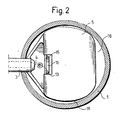
- Fig. 2 is a cross-section through the nebulizer in Fig. 1, with a holder arrangement for the deflector plate also being shown.
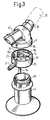
- Fig. 3 is an exploded view of a preferred embodiment of a nebulizer according to the invention.
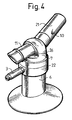
- Fig. 4 shows the nebulizer according to Fig. 3 in the assembled state.
- reference number 1 designates the housing of a nebulizer according to the invention, containing a supply 2 of a medical preparation in liquid form.
- the preparation can also be in powder form and be mixed with a liquid.
- Reference number 3 designates a gas inlet for a carrier gas, such as air or a gas mixture containing helium and/or neon and oxygen.
- the carrier gas is delivered at a pressure of the order of 1 - 10 bar, preferably about 5 bar.
- the flow is adapted by configuring the nozzle 4 to the patient's inspiratory volume per minute, which, for an adult with normal pulmonary function, is about 4.5 litres/minute.
- Reference number 5 designates a curved deflector plate which essentially screens off the lower part 6 of the housing 1, containing the liquid magazine 2, from the upper part 7 of the housing, having an outlet 8 intended to be connected to a mouthpiece which the patient will breathe through.
- the outlet 8 is provided with a nonreturn valve 9 and one or more exhalation openings 10.
- the illustrated embodiment is also provided with an outlet 11 connected to a flexible dosing bag 12.
- the nozzle 4 forms a gas jet which is directed essentially at right angles to the axial extent of a channel 14 which communicates with the liquid magazine 2. At least part of the gas jet passes, with expansion, closely across the mouth 13 of the channel 14. The gas jet will thus suck liquid particles with it in the form of an aerosol from the mouth 13 and will bring these into contact with a vertical stop surface 15. In the resulting aerosol, the larger liquid particles in particular strike the stop surface 15 and will be broken up, on contact with the latter, to form a more finely atomized, second aerosol, which rises upwards in the housing 1.
- the distance from the centre of the mouth 13 to the nozzle 4 is expediently 1 - 3 mm, preferably about 2 mm.
- the nozzle 4 is situated at a lower level than the mouth 13, the distance in the vertical direction between the centre line of the nozzle 4 and the mouth 13 being 0.1 - 1 mm, preferably about 0.3 mm.
- a plate can be arranged to extend from the top side of the nozzle 4 and forwards across the mouth 13 of the liquid channel. The plate expediently slopes slightly upwards in the direction of the said mouth.
- the stop surface 15, designed in the form of a plate, has sharp upper edges, and is provided on its rear surface, as viewed in the direction of flow of the gas jet, with an outwardly protruding plateau 16 having a length of 1 - 10 mm, preferably about 2 mm.
- the plateau has the effect, inter alia, that an underpressure is created on the rear side of the stop plate 15, and this imparts a downward force to the aerosol stream, which prevents this from being directed too high.
- the plateau can also be located level with the upper edge of the plate 15.
- the front surface of the plate can be provided with a screen arranged at its upper edge and/or with a recess where the gas jet hits the surface.
- the aerosol finely atomized by the plate 15 passes upwards in the housing 1, its flow movements being influenced by the deflector plate 5. Especially the larger particles in the aerosol hit the plate and run down along the latter and are returned to the liquid magazine 2.
- These passages 17 and 18, respectively, can have a height or width of 0.5-4 mm, preferably about 1 mm, and a length of 5 - 20 mm, preferably about 15 mm.
- the plate 5, together with the slit-shaped passages 17, 18, will act on the flow characteristics of the aerosol and will make it possible in advance, by means of suitable dimensioning of the said passages, inter alia as a function of the pressure of the delivered gas, to achieve the desired size distribution of the liquid particles in the final aerosol.
- the slits 17 and 18 form labyrinthine passages which require changes in the direction of the liquid particles in the aerosol in order for them to pass.
- the passage 18 also allows liquid which condenses in the upper part of the housing 1 to return to the liquid magazine.
- a deflector plate 5 it is thus possible, as a function of the dimensions and design of, above all, the slits 17 and 18, to act on the size distribution of the particles in the final aerosol and thus to adapt this aerosol to the requirements of the patient groups, the drug in question, and the site in the lungs where deposition is desired.
- the aerosol After passing the deflector plate 5, the aerosol reaches the outlet 8 and is inhaled by the patient, with the nonreturn valve 9 opening. On exhaling, the nonreturn valve closes, whereupon the exhaled air has to pass out through the opening 10.
- the patient is thus able to inhale and exhale completely normally without removing from his/her mouth a mouthpiece attached to the inlet 8.
- the area of the exhalation opening 10 is adapted to offer a certain resistance to exhalation, which means that the patient's airways are spread open, and breathing and deposition of the medical aerosol are improved. If the drug is of a type which requires that even small leakages of medicine to the environment have to be prevented, then a medical filter can be arranged in connection with the exhalation opening 10.
- the aerosol formation continues even during the exhalation phase, for which reason the housing 1 has been provided with an outlet opening 11 to which a flexible dosing bag 12 is connected.
- This dosing bag will fill as the patient exhales and will empty during the succeeding inhalation.
- the stream of gas to the arrangement, and thus the production of aerosol is adapted such that it corresponds to, or is slightly less than, the patient's inspiratory volume, and any additional air will be inhaled via the opening 10.
- One of the advantages achieved by adapting the quantity of aerosol produced per unit time and the size of the dosing bag to the inspiratory volume is the following. It is greatly desired that the dose of medicine supplied on each inhalation will be deposited in the lungs, since that aerosol which reaches the upper airways and the oral cavity and throat deposits the drug at an undesired site, where it has no appreciable impact or may cause side effects. Alternatively, it will be exhaled to no benefit and may create problems for the environment.
- the dosing bag having a defined volume which is less than the inspiratory volume the last-inhaled volume in each respiration will consist essentially of pure air, which is drawn in via the opening 10, together with a small quantity of aerosol which is produced during the actual inhalation.
- This diluted gas volume will settle as a cushion in the upper airways and thereby prevents the drug from being deposited at an undesired site.
- the aim may be to concentrate the deposition of the drug in the peripheral regions of the lungs. This can be done by producing an aerosol which is of considerably smaller volume than the inspiratory volume and which is inhaled first during respiration.
- the medicine included therein is thus deposited essentially in the peripheral regions of the lungs, while the rest of the lungs and airways are filled essentially with pure air, which is inhaled after the dose of medicine.
- Figs 3 and 4 show a preferred embodiment of a nebulizer according to the invention which works according to the principle which has been described in conjunction with Figs 1 and 2.
- the same reference numbers have been used for those components in Figs 3 and 4 which correspond to components in Figs 1 and 2.
- Fig. 3 shows that the nebulizer is made up of a lower part 6, which contains a liquid magazine and is provided with an outer thread 20 for cooperation with a corresponding inner thread on the upper part 7.
- a suction mouthpiece 21 equipped with a nonreturn valve can be connected to the part 7.
- This suction mouthpiece 21 expediently has a round shape in order to prevent the patient from unintentionally closing his/her mouth and in this way drawing the aerosol through the teeth.
- the part 7 moreover carries the outlet 11 which is intended to be connected to a dosing bag (not shown).
- Reference number 22 designates an intermediate unit which carries the gas attachment 3, which leads to the nozzle 4, in Fig. 1, located on the rear side of a sloping wall 23.
- the channel 14 designed in the shape of a pipe protrudes down under the part 22 and has its upper mouth 13, in Fig. 1, located alongside the gas nozzle.
- the wall 23 collects the aerosol after this has hit the stop plate 15, in Fig. 1, and it conveys some of this aerosol up through an opening 24, so that it can be deflected and can pass to the top side of the deflection plate 5. The remainder passes along the underside of the plate towards the slit 18. Some also passes through the slit 19.
- a horizontal portion 26 of the part 7 will be situated immediately above the plate 5 and, together with this, will form the slit 17, in Fig. 1, with predetermined dimensions.
- the plate 5 is also dimensioned in such a way that a slit 18 according to Fig. 1 is formed between the rear edge of the plate and the circular wall of the part 22, and a slit 19 is formed between the side edges of the plate 5 and the circular wall.
- the above-described embodiment has the great advantage that all the critical parts of the nebulizer which may need to be varied to achieve the desired function are found in one exchangeable part 22 designed as one unit.
- the nebulizer can thus be used with different configurations of the components in part 22 in order, inter alia, to produce the size distribution, desired in the case in question, of the liquid particles in the resulting aerosol.
- the shape of the deflector plate 5 can be varied.
- it can consist of an inclined, flat plate. It can also be designed in such a way that there is a slit only at one edge, expediently the front edge.
- the arrangement can also be-used without a dosing bag, in which case the outlet 11 is omitted.
- the nozzle 13 can be designed in the shape of a shallow dish.
Landscapes
- Health & Medical Sciences (AREA)
- Engineering & Computer Science (AREA)
- Life Sciences & Earth Sciences (AREA)
- Animal Behavior & Ethology (AREA)
- Anesthesiology (AREA)
- Biomedical Technology (AREA)
- Heart & Thoracic Surgery (AREA)
- Hematology (AREA)
- Veterinary Medicine (AREA)
- Public Health (AREA)
- General Health & Medical Sciences (AREA)
- Pulmonology (AREA)
- Bioinformatics & Cheminformatics (AREA)
- Containers And Packaging Bodies Having A Special Means To Remove Contents (AREA)
- Medicinal Preparation (AREA)
- Nozzles (AREA)
Claims (12)
- Procédé pour produire un aérosol finement atomisé, comprenant le fait de diriger un jet de gaz à partir d'un bec à gaz (4) pour passer à travers l'embouchure (13) d'un canal à liquide (14), qui communique avec une alimentation (2) de liquide dans un récipient (6), de telle sorte que le liquide est aspiré de l'embouchure (13) du canal à liquide (14) par ledit jet de gaz, afin de former un premier aérosol, après lequel les particules de liquide dans le premier aérosol sont éclatées en des particules plus petites dans une phase suivante pour former un deuxième aérosol, caractérisé par le fait de faire percuter essentiellement toutes les particules de liquide dans le premier aérosol contre une surface d'arrêt (15) située à une distance proche devant le bec à gaz (4) pour éclater les particules de liquide dans le premier aérosol pour former le deuxième aérosol plus finement atomisé, dirigeant les particules dans le deuxième aérosol vers une plaque déflectrice (5) détournant les particules de liquide vers un ou plusieurs passages étroits en forme de fente (17, 18) d'une largeur prédéterminée où elles se mélangent avec la partie restante du deuxième aérosol et forçant le mélange à suivre un trajet labyrinthique changeant de direction et passant à travers lesdits passages en forme de fente (17, 18) pour former un troisième aérosol ayant une distribution, de taille prédéterminée, de particules de liquide, déterminée par la largeur fixe desdits passages (17, 18).
- Procédé selon la revendication 1 pour produire un aérosol pour inhalation, caractérisé en ce que l'aérosol est produit de manière continue en une quantité qui correspond au, ou est légèrement inférieure au, volume inspiré du patient qui doit l'inhaler, et en ce que l'aérosol qui est formé entre les respirations est rassemblé dans un sac de dosage (12), qui se vide durant la respiration suivante.
- Procédé selon la revendication 2, caractérisé en ce qu'un aérosol de volume considérablement inférieur au volume inspiré est produit de telle sorte que le médicament inclus dans l'aérosol est essentiellement déposé dans les régions périphériques des poumons, alors que le reste des poumons et voies aériennes sont remplis principalement d'air.
- Agencement pour produire un aérosol finement atomisé, comprenant un bec à gaz (4) conçu pour éjecter un jet de gaz pour passer à travers l'embouchure (13) d'un canal à liquide (14), qui communique avec une alimentation (2) de liquide dans un récipient (6), de telle sorte que le liquide est aspiré de l'embouchure (13) du canal à liquide (14) par ledit jet de gaz, afin de former un premier aérosol, et un élément qui, dans une deuxième phase, éclate les particules de liquide dans le premier aérosol en des particules plus petites pour former un deuxième aérosol, caractérisé en ce que ledit élément dernièrement mentionné comprend une surface d'arrêt (15) située à une distance proche devant le bec à gaz (4), de telle sorte qu'essentiellement toutes les particules de liquide dans le premier aérosol percutent la surface d'arrêt (15) et sont éclatées sous la formation du deuxième aérosol plus finement atomisé, l'agencement comprenant en outre une plaque déflectrice (5), qui avec un logement environnant (1) forme au moins un passage étroit en forme de fente (17, 18) d'une largeur prédéterminée, laquelle plaque (5) détourne les particules de liquide dans le deuxième aérosol vers ledit passage en forme de fente (17, 18), où elles se mélangent avec le reste du deuxième aérosol, ledit passage en forme de fente (17, 18) et la plaque déflectrice (5) formant un trajet labyrinthique amenant le mélange à changer de direction et passer à travers au moins un passage en forme de fente (17, 18) pour former un troisième aérosol ayant une distribution, de taille prédéterminée, de particules de liquides, déterminée par la largeur fixe d'au moins un dit passage (17, 18).
- Agencement selon la revendication 4, caractérisé en ce que la plaque déflectrice (5) est courbée et est située à une distance au-dessus de l'embouchure (13) du canal à liquide, et en ce qu'un passage en forme de fente (17, 18) est formé le long des bords avant et arrière de la plaque (5) comme il est vu dans la direction du jet de gaz à travers l'embouchure du canal à liquide.
- Agencement selon la revendication 4 ou 5, caractérisé en ce que les passages en forme de fente (17, 18) ont une largeur ou hauteur de 0,5 à 4 mm, de préférence environ 1 mm, et une longueur de 5 à 20 mm, de préférence environ 15 mm.
- Agencement selon l'une quelconque des revendications 4 à 6, caractérisé en ce que le jet de gaz est distribué via une entrée de gaz (3, 4) qui débouche à un niveau plus bas que l'embouchure (13) du canal à liquide, opportunément de 0,1 à 1 mm, et de préférence environ 0,3 mm, sous l'embouchure.
- Agencement selon l'une quelconque des revendications 4 à 7, caractérisé en ce que la plaque d'arrêt (15) est située de 0,1 à 2 mm, de préférence environ 1 mm, derrière l'embouchure (13) du canal à liquide.
- Agencement selon l'une quelconque des revendications 4 à 8, caractérisé en ce que la plaque d'arrêt (15) a des bords supérieurs coupants, et un plateau (16) en saillie par rapport au côté arrière et dans la direction prise par le jet de gaz.
- Agencement selon la revendication 9, caractérisé en ce que le plateau (16) est situé à un niveau plus bas que la surface du bord supérieur de la plaque (15), et s'étend de 1 à 10 mm, de préférence 2 à 5 mm, dans la direction prise par le jet de gaz.
- Agencement selon l'une quelconque des revendications 4 à 10, caractérisé en ce qu'il comprend une plaque qui s'étend à travers l'entrée de gaz (4) et vers l'avant à travers l'embouchure (13) du canal à liquide.
- Agencement selon l'une quelconque des revendications 4 à 11, caractérisé en ce que la plaque déflectrice (5) constitue une partie d'une unité échangeable, qui comprend aussi ledit canal à liquide (14), lesdits éléments (3, 4) pour diriger le jet de gaz, ainsi que la plaque d'arrêt (15).
Applications Claiming Priority (3)
| Application Number | Priority Date | Filing Date | Title |
|---|---|---|---|
| SE9603804A SE9603804D0 (sv) | 1996-10-16 | 1996-10-16 | Sätt och anordning för framställning av en finfördelad aerosol |
| SE9603804 | 1996-10-16 | ||
| PCT/SE1997/001728 WO1998016271A1 (fr) | 1996-10-16 | 1997-10-15 | Procede et appareil de production d'un aerosol fin homogene |
Publications (2)
| Publication Number | Publication Date |
|---|---|
| EP0932425A1 EP0932425A1 (fr) | 1999-08-04 |
| EP0932425B1 true EP0932425B1 (fr) | 2003-02-19 |
Family
ID=20404286
Family Applications (1)
| Application Number | Title | Priority Date | Filing Date |
|---|---|---|---|
| EP97909812A Expired - Lifetime EP0932425B1 (fr) | 1996-10-16 | 1997-10-15 | Procede et appareil de production d'un aerosol fin homogene |
Country Status (5)
| Country | Link |
|---|---|
| US (1) | US6223745B1 (fr) |
| EP (1) | EP0932425B1 (fr) |
| DE (1) | DE69719202T2 (fr) |
| SE (1) | SE9603804D0 (fr) |
| WO (1) | WO1998016271A1 (fr) |
Families Citing this family (50)
| Publication number | Priority date | Publication date | Assignee | Title |
|---|---|---|---|---|
| US5823179A (en) * | 1996-02-13 | 1998-10-20 | 1263152 Ontario Inc. | Nebulizer apparatus and method |
| US6044841A (en) * | 1997-08-29 | 2000-04-04 | 1263152 Ontario Inc. | Breath actuated nebulizer with valve assembly having a relief piston |
| US6314609B1 (en) * | 2000-02-07 | 2001-11-13 | Connie George | Mouth powered vacuum |
| EP1272243B1 (fr) | 2000-04-11 | 2005-10-26 | Trudell Medical International | Appareil aerosol avec une capacite de pression expiratoire positive |
| US6363932B1 (en) * | 2000-07-06 | 2002-04-02 | Clinical Technologies, Inc. | Aerosol enhancement device |
| US7204245B2 (en) * | 2000-07-06 | 2007-04-17 | Clinical Technologies, Inc | Aerosol enhancement device |
| AU2002238801A1 (en) * | 2001-03-20 | 2002-10-03 | Trudell Medical International | Nebulizer apparatus and method |
| JP2005511211A (ja) * | 2001-12-05 | 2005-04-28 | ニュファームクス, エルエルシー | ヘリオックスを用いるエアロゾル化した薬物の吸入のための医療デバイスおよび方法 |
| US6994083B2 (en) * | 2001-12-21 | 2006-02-07 | Trudell Medical International | Nebulizer apparatus and method |
| KR100439991B1 (ko) * | 2002-03-15 | 2004-07-12 | (주)메가메디칼 | 의료용 스프레이 장치 |
| US20030205226A1 (en) | 2002-05-02 | 2003-11-06 | Pre Holding, Inc. | Aerosol medication inhalation system |
| US8245708B2 (en) * | 2002-05-07 | 2012-08-21 | The Research Foundation Of State University Of New York | Methods, devices and formulations for targeted endobronchial therapy |
| AU2003223094A1 (en) * | 2002-05-08 | 2003-11-11 | Medihale Ltd. | Hand held device for inhalation therapy and method of use thereof |
| US6904908B2 (en) | 2002-05-21 | 2005-06-14 | Trudell Medical International | Visual indicator for an aerosol medication delivery apparatus and system |
| US8118769B2 (en) * | 2002-07-19 | 2012-02-21 | Storz Endoskop Produktions Gmbh | Apparatus for conditioning an insufflation gas |
| FR2852262B1 (fr) * | 2003-03-11 | 2007-01-12 | Procede et dispositif de nebulisation. | |
| US7360537B2 (en) * | 2003-04-16 | 2008-04-22 | Trudell Medical International | Antistatic medication delivery apparatus |
| US7270123B2 (en) * | 2003-08-13 | 2007-09-18 | Trudell Medical International | Nebulizer apparatus and method |
| US9022027B2 (en) | 2004-02-20 | 2015-05-05 | Pneumoflex Systems, Llc | Nebulizer with intra-oral vibrating mesh |
| US8109266B2 (en) | 2004-02-20 | 2012-02-07 | Pneumoflex Systems, Llc | Nebulizer having flow meter function |
| US20050183718A1 (en) | 2004-02-24 | 2005-08-25 | Boehringer Ingelheim International Gmbh | Nebulizer |
| US20080245362A1 (en) * | 2005-09-06 | 2008-10-09 | George Moessis | Nebuliser |
| US20070137648A1 (en) * | 2005-12-16 | 2007-06-21 | Pneumoflex Systems, Llc | Intraoral Nebulizer Providing Air Curtains |
| US8551534B2 (en) | 2007-10-10 | 2013-10-08 | Parion Sciences, Inc. | Inhaled hypertonic saline delivered by a heated nasal cannula |
| US20090255035A1 (en) * | 2008-04-14 | 2009-10-15 | Wade Little | Adjustable Hat with a Customized Structure |
| US8671934B2 (en) | 2011-01-20 | 2014-03-18 | Pneumoflex Systems, Llc | Nebulizer that is activated by negative inspiratory pressure |
| US9452270B2 (en) | 2011-01-20 | 2016-09-27 | Pneumoflex Systems, Llc | Nebulizer having replaceable nozzle assembly and suction line |
| US20140207016A1 (en) | 2011-01-20 | 2014-07-24 | Pneumoflex Systems, Llc | Pulsed nebulizer |
| US8778383B2 (en) | 2011-06-07 | 2014-07-15 | Parion Sciences, Inc. | Methods of treatment |
| US8945605B2 (en) * | 2011-06-07 | 2015-02-03 | Parion Sciences, Inc. | Aerosol delivery systems, compositions and methods |
| PL2753202T3 (pl) | 2011-09-06 | 2016-11-30 | Podgrzewanie materiału przeznaczonego do palenia | |
| US9326547B2 (en) * | 2012-01-31 | 2016-05-03 | Altria Client Services Llc | Electronic vaping article |
| GB201217067D0 (en) | 2012-09-25 | 2012-11-07 | British American Tobacco Co | Heating smokable material |
| GB201311620D0 (en) | 2013-06-28 | 2013-08-14 | British American Tobacco Co | Devices Comprising a Heat Source Material and Activation Chambers for the Same |
| GB201500582D0 (en) | 2015-01-14 | 2015-02-25 | British American Tobacco Co | Apparatus for heating or cooling a material contained therein |
| TWD169846S (zh) * | 2014-12-12 | 2015-08-11 | 李文欽 | 噴霧器(二) |
| US20170055575A1 (en) | 2015-08-31 | 2017-03-02 | British American Tobacco (Investments) Limited | Material for use with apparatus for heating smokable material |
| US20170055584A1 (en) | 2015-08-31 | 2017-03-02 | British American Tobacco (Investments) Limited | Article for use with apparatus for heating smokable material |
| US11924930B2 (en) | 2015-08-31 | 2024-03-05 | Nicoventures Trading Limited | Article for use with apparatus for heating smokable material |
| US20170119046A1 (en) | 2015-10-30 | 2017-05-04 | British American Tobacco (Investments) Limited | Apparatus for Heating Smokable Material |
| US20170119047A1 (en) | 2015-10-30 | 2017-05-04 | British American Tobacco (Investments) Limited | Article for Use with Apparatus for Heating Smokable Material |
| ES2966349T3 (es) | 2016-05-19 | 2024-04-22 | Trudell Medical Int | Cámara de retención con válvula inteligente |
| US10786638B2 (en) | 2016-07-08 | 2020-09-29 | Trudell Medical International | Nebulizer apparatus and method |
| ES2988939T3 (es) | 2016-07-08 | 2024-11-22 | Trudell Medical Int Inc | Dispositivo de presión espiratoria positiva oscilante inteligente |
| CN110049795B (zh) | 2016-12-09 | 2022-07-19 | 特鲁德尔医学国际公司 | 智能雾化器 |
| US11666801B2 (en) | 2018-01-04 | 2023-06-06 | Trudell Medical International | Smart oscillating positive expiratory pressure device |
| CN110251782A (zh) * | 2019-06-17 | 2019-09-20 | 南京航空航天大学 | 一种医用雾化装置 |
| WO2021038467A1 (fr) | 2019-08-27 | 2021-03-04 | Trudell Medical International | Dispositif intelligent à pression expiratoire positive oscillante |
| CN112493552B (zh) * | 2020-11-16 | 2025-03-14 | 深圳市吉迩科技有限公司 | 一种防止堵孔的双气道装置及气溶胶产生装置 |
| CN112716532B (zh) * | 2020-12-28 | 2024-04-30 | 中国科学院合肥物质科学研究院 | 一种呼气气溶胶采集检测装置及其检测方法 |
Family Cites Families (9)
| Publication number | Priority date | Publication date | Assignee | Title |
|---|---|---|---|---|
| US240421A (en) * | 1881-04-19 | Anthony iske | ||
| US3097645A (en) * | 1960-03-22 | 1963-07-16 | Victor E Lester | Nebulizer |
| US3744722A (en) * | 1970-12-29 | 1973-07-10 | Cavitron Corp | Nebulizer |
| US4007238A (en) * | 1976-02-25 | 1977-02-08 | Glenn Joseph G | Nebulizer for use with IPPB equipment |
| AU6300580A (en) * | 1980-10-07 | 1982-04-22 | Kalnin, L.N. | Nebulizer |
| US4484577A (en) | 1981-07-23 | 1984-11-27 | Key Pharmaceuticals, Inc. | Drug delivery method and inhalation device therefor |
| DE3429389C1 (de) * | 1984-08-09 | 1986-03-13 | Brugger, Inge, geb. Ritzau, 8130 Starnberg | Inhalator |
| US5241954A (en) | 1991-05-24 | 1993-09-07 | Glenn Joseph G | Nebulizer |
| US5287847A (en) * | 1992-07-24 | 1994-02-22 | Vortran Medical Technology, Inc. | Universal nebulizer |
-
1996
- 1996-10-16 SE SE9603804A patent/SE9603804D0/xx unknown
-
1997
- 1997-10-15 EP EP97909812A patent/EP0932425B1/fr not_active Expired - Lifetime
- 1997-10-15 WO PCT/SE1997/001728 patent/WO1998016271A1/fr not_active Ceased
- 1997-10-15 DE DE69719202T patent/DE69719202T2/de not_active Expired - Lifetime
- 1997-10-15 US US09/284,515 patent/US6223745B1/en not_active Expired - Fee Related
Also Published As
| Publication number | Publication date |
|---|---|
| EP0932425A1 (fr) | 1999-08-04 |
| SE9603804D0 (sv) | 1996-10-16 |
| DE69719202T2 (de) | 2003-10-23 |
| WO1998016271A1 (fr) | 1998-04-23 |
| US6223745B1 (en) | 2001-05-01 |
| DE69719202D1 (de) | 2003-03-27 |
Similar Documents
| Publication | Publication Date | Title |
|---|---|---|
| EP0932425B1 (fr) | Procede et appareil de production d'un aerosol fin homogene | |
| US5522380A (en) | Metered dose medication adaptor with improved incentive spirometer | |
| US5975076A (en) | Dry powder inhalers | |
| JP3223300B2 (ja) | 散剤吸入器のための分離装置 | |
| EP0940154B1 (fr) | Dispositif pour administrer des aérosols de médicaments | |
| US7712466B2 (en) | Intra-oral nebulizer | |
| JP3993894B2 (ja) | ネブライザー装置および方法 | |
| US5170782A (en) | Medicament nebulizer with improved aerosol chamber | |
| US6681767B1 (en) | Method and device for delivering aerosolized medicaments | |
| US5875774A (en) | Nebulizer | |
| AU641268B2 (en) | Inhalation device | |
| JP5071991B2 (ja) | 単位投薬量カートリッジおよび乾燥粉末吸入器 | |
| EP0957960B1 (fr) | Appareil a circuit respiratoire pour nebuliseur | |
| US7726306B2 (en) | Intra-oral nebulizer with rainfall chamber | |
| EP0855224A2 (fr) | Atomiseur | |
| EP0641570A1 (fr) | Nébulisateur | |
| JPH08502904A (ja) | 低流量ネブライザ、噴霧化方法及び装置 | |
| JP2007526055A (ja) | 多チャネル型ノズルを有する粉末吸入器 | |
| WO1998031411A1 (fr) | Dispositif pour aerosol | |
| CA2210721C (fr) | Adaptateur pour doseur de medicaments ayant un spirometre de stimulation ameliore | |
| GB2233919A (en) | "Aerosol delivery apparatus" | |
| JPH05317427A (ja) | 吸入方法と装置 | |
| MXPA97009415A (en) | Breathing circuit apparatus for a nebuliza |
Legal Events
| Date | Code | Title | Description |
|---|---|---|---|
| PUAI | Public reference made under article 153(3) epc to a published international application that has entered the european phase |
Free format text: ORIGINAL CODE: 0009012 |
|
| 17P | Request for examination filed |
Effective date: 19990415 |
|
| AK | Designated contracting states |
Kind code of ref document: A1 Designated state(s): DE FR GB |
|
| 17Q | First examination report despatched |
Effective date: 20010208 |
|
| GRAG | Despatch of communication of intention to grant |
Free format text: ORIGINAL CODE: EPIDOS AGRA |
|
| GRAG | Despatch of communication of intention to grant |
Free format text: ORIGINAL CODE: EPIDOS AGRA |
|
| GRAH | Despatch of communication of intention to grant a patent |
Free format text: ORIGINAL CODE: EPIDOS IGRA |
|
| GRAH | Despatch of communication of intention to grant a patent |
Free format text: ORIGINAL CODE: EPIDOS IGRA |
|
| GRAA | (expected) grant |
Free format text: ORIGINAL CODE: 0009210 |
|
| AK | Designated contracting states |
Designated state(s): DE FR GB |
|
| REG | Reference to a national code |
Ref country code: GB Ref legal event code: FG4D |
|
| REF | Corresponds to: |
Ref document number: 69719202 Country of ref document: DE Date of ref document: 20030327 Kind code of ref document: P |
|
| ET | Fr: translation filed | ||
| PLBE | No opposition filed within time limit |
Free format text: ORIGINAL CODE: 0009261 |
|
| STAA | Information on the status of an ep patent application or granted ep patent |
Free format text: STATUS: NO OPPOSITION FILED WITHIN TIME LIMIT |
|
| 26N | No opposition filed |
Effective date: 20031120 |
|
| PGFP | Annual fee paid to national office [announced via postgrant information from national office to epo] |
Ref country code: DE Payment date: 20091008 Year of fee payment: 13 |
|
| PGFP | Annual fee paid to national office [announced via postgrant information from national office to epo] |
Ref country code: GB Payment date: 20091014 Year of fee payment: 13 Ref country code: FR Payment date: 20091029 Year of fee payment: 13 |
|
| GBPC | Gb: european patent ceased through non-payment of renewal fee |
Effective date: 20101015 |
|
| PG25 | Lapsed in a contracting state [announced via postgrant information from national office to epo] |
Ref country code: FR Free format text: LAPSE BECAUSE OF NON-PAYMENT OF DUE FEES Effective date: 20101102 |
|
| REG | Reference to a national code |
Ref country code: FR Ref legal event code: ST Effective date: 20110630 |
|
| PG25 | Lapsed in a contracting state [announced via postgrant information from national office to epo] |
Ref country code: GB Free format text: LAPSE BECAUSE OF NON-PAYMENT OF DUE FEES Effective date: 20101015 |
|
| REG | Reference to a national code |
Ref country code: DE Ref legal event code: R119 Ref document number: 69719202 Country of ref document: DE Effective date: 20110502 |
|
| PG25 | Lapsed in a contracting state [announced via postgrant information from national office to epo] |
Ref country code: DE Free format text: LAPSE BECAUSE OF NON-PAYMENT OF DUE FEES Effective date: 20110502 |