EP0932439B1 - Commande de reaction en boucle fermee pour concentrateur d'oxygene - Google Patents
Commande de reaction en boucle fermee pour concentrateur d'oxygene Download PDFInfo
- Publication number
- EP0932439B1 EP0932439B1 EP98926313A EP98926313A EP0932439B1 EP 0932439 B1 EP0932439 B1 EP 0932439B1 EP 98926313 A EP98926313 A EP 98926313A EP 98926313 A EP98926313 A EP 98926313A EP 0932439 B1 EP0932439 B1 EP 0932439B1
- Authority
- EP
- European Patent Office
- Prior art keywords
- concentration
- bed
- gas
- valve
- beds
- Prior art date
- Legal status (The legal status is an assumption and is not a legal conclusion. Google has not performed a legal analysis and makes no representation as to the accuracy of the status listed.)
- Expired - Lifetime
Links
- QVGXLLKOCUKJST-UHFFFAOYSA-N atomic oxygen Chemical compound [O] QVGXLLKOCUKJST-UHFFFAOYSA-N 0.000 title claims abstract description 52
- 239000001301 oxygen Substances 0.000 title claims abstract description 52
- 229910052760 oxygen Inorganic materials 0.000 title claims abstract description 52
- 239000007789 gas Substances 0.000 claims abstract description 97
- 238000004891 communication Methods 0.000 claims abstract description 15
- 239000012530 fluid Substances 0.000 claims abstract description 12
- 238000000034 method Methods 0.000 claims description 25
- 238000005194 fractionation Methods 0.000 claims description 10
- 230000008859 change Effects 0.000 claims description 6
- 230000001105 regulatory effect Effects 0.000 claims description 3
- 230000003247 decreasing effect Effects 0.000 claims 1
- 239000002808 molecular sieve Substances 0.000 abstract description 16
- URGAHOPLAPQHLN-UHFFFAOYSA-N sodium aluminosilicate Chemical compound [Na+].[Al+3].[O-][Si]([O-])=O.[O-][Si]([O-])=O URGAHOPLAPQHLN-UHFFFAOYSA-N 0.000 abstract description 16
- IJGRMHOSHXDMSA-UHFFFAOYSA-N Atomic nitrogen Chemical compound N#N IJGRMHOSHXDMSA-UHFFFAOYSA-N 0.000 abstract description 14
- 238000010926 purge Methods 0.000 abstract description 11
- 229910052757 nitrogen Inorganic materials 0.000 abstract description 7
- 239000008246 gaseous mixture Substances 0.000 description 17
- 239000000203 mixture Substances 0.000 description 10
- 238000000926 separation method Methods 0.000 description 9
- 238000001179 sorption measurement Methods 0.000 description 8
- 229910021536 Zeolite Inorganic materials 0.000 description 7
- HNPSIPDUKPIQMN-UHFFFAOYSA-N dioxosilane;oxo(oxoalumanyloxy)alumane Chemical compound O=[Si]=O.O=[Al]O[Al]=O HNPSIPDUKPIQMN-UHFFFAOYSA-N 0.000 description 7
- 239000010457 zeolite Substances 0.000 description 7
- 238000004519 manufacturing process Methods 0.000 description 6
- 230000008901 benefit Effects 0.000 description 5
- 239000000463 material Substances 0.000 description 5
- 239000011148 porous material Substances 0.000 description 4
- 239000002912 waste gas Substances 0.000 description 4
- 230000029058 respiratory gaseous exchange Effects 0.000 description 3
- CURLTUGMZLYLDI-UHFFFAOYSA-N Carbon dioxide Chemical compound O=C=O CURLTUGMZLYLDI-UHFFFAOYSA-N 0.000 description 2
- 230000001276 controlling effect Effects 0.000 description 2
- 230000001351 cycling effect Effects 0.000 description 2
- 238000003795 desorption Methods 0.000 description 2
- 238000009792 diffusion process Methods 0.000 description 2
- 238000012856 packing Methods 0.000 description 2
- 230000008569 process Effects 0.000 description 2
- OYPRJOBELJOOCE-UHFFFAOYSA-N Calcium Chemical group [Ca] OYPRJOBELJOOCE-UHFFFAOYSA-N 0.000 description 1
- UGFAIRIUMAVXCW-UHFFFAOYSA-N Carbon monoxide Chemical compound [O+]#[C-] UGFAIRIUMAVXCW-UHFFFAOYSA-N 0.000 description 1
- UFHFLCQGNIYNRP-UHFFFAOYSA-N Hydrogen Chemical compound [H][H] UFHFLCQGNIYNRP-UHFFFAOYSA-N 0.000 description 1
- DGAQECJNVWCQMB-PUAWFVPOSA-M Ilexoside XXIX Chemical compound C[C@@H]1CC[C@@]2(CC[C@@]3(C(=CC[C@H]4[C@]3(CC[C@@H]5[C@@]4(CC[C@@H](C5(C)C)OS(=O)(=O)[O-])C)C)[C@@H]2[C@]1(C)O)C)C(=O)O[C@H]6[C@@H]([C@H]([C@@H]([C@H](O6)CO)O)O)O.[Na+] DGAQECJNVWCQMB-PUAWFVPOSA-M 0.000 description 1
- 239000003463 adsorbent Substances 0.000 description 1
- 229910052782 aluminium Inorganic materials 0.000 description 1
- 229910002092 carbon dioxide Inorganic materials 0.000 description 1
- 239000001569 carbon dioxide Substances 0.000 description 1
- 229910002091 carbon monoxide Inorganic materials 0.000 description 1
- 125000004122 cyclic group Chemical class 0.000 description 1
- 230000007423 decrease Effects 0.000 description 1
- 230000001419 dependent effect Effects 0.000 description 1
- 238000010586 diagram Methods 0.000 description 1
- 238000001035 drying Methods 0.000 description 1
- -1 e.g. Substances 0.000 description 1
- 238000011010 flushing procedure Methods 0.000 description 1
- 230000002431 foraging effect Effects 0.000 description 1
- 229930195733 hydrocarbon Natural products 0.000 description 1
- 150000002430 hydrocarbons Chemical class 0.000 description 1
- 239000001257 hydrogen Substances 0.000 description 1
- 229910052739 hydrogen Inorganic materials 0.000 description 1
- 238000005259 measurement Methods 0.000 description 1
- 230000007246 mechanism Effects 0.000 description 1
- 238000005457 optimization Methods 0.000 description 1
- 230000010355 oscillation Effects 0.000 description 1
- 239000011734 sodium Substances 0.000 description 1
- 229910052708 sodium Inorganic materials 0.000 description 1
- 238000013022 venting Methods 0.000 description 1
- 230000000007 visual effect Effects 0.000 description 1
- XLYOFNOQVPJJNP-UHFFFAOYSA-N water Chemical compound O XLYOFNOQVPJJNP-UHFFFAOYSA-N 0.000 description 1
Images


Classifications
-
- B—PERFORMING OPERATIONS; TRANSPORTING
- B01—PHYSICAL OR CHEMICAL PROCESSES OR APPARATUS IN GENERAL
- B01D—SEPARATION
- B01D53/00—Separation of gases or vapours; Recovering vapours of volatile solvents from gases; Chemical or biological purification of waste gases, e.g. engine exhaust gases, smoke, fumes, flue gases, aerosols
- B01D53/02—Separation of gases or vapours; Recovering vapours of volatile solvents from gases; Chemical or biological purification of waste gases, e.g. engine exhaust gases, smoke, fumes, flue gases, aerosols by adsorption, e.g. preparative gas chromatography
- B01D53/04—Separation of gases or vapours; Recovering vapours of volatile solvents from gases; Chemical or biological purification of waste gases, e.g. engine exhaust gases, smoke, fumes, flue gases, aerosols by adsorption, e.g. preparative gas chromatography with stationary adsorbents
- B01D53/047—Pressure swing adsorption
-
- A—HUMAN NECESSITIES
- A61—MEDICAL OR VETERINARY SCIENCE; HYGIENE
- A61M—DEVICES FOR INTRODUCING MEDIA INTO, OR ONTO, THE BODY; DEVICES FOR TRANSDUCING BODY MEDIA OR FOR TAKING MEDIA FROM THE BODY; DEVICES FOR PRODUCING OR ENDING SLEEP OR STUPOR
- A61M16/00—Devices for influencing the respiratory system of patients by gas treatment, e.g. ventilators; Tracheal tubes
- A61M16/10—Preparation of respiratory gases or vapours
- A61M16/1005—Preparation of respiratory gases or vapours with O2 features or with parameter measurement
- A61M16/101—Preparation of respiratory gases or vapours with O2 features or with parameter measurement using an oxygen concentrator
-
- B—PERFORMING OPERATIONS; TRANSPORTING
- B01—PHYSICAL OR CHEMICAL PROCESSES OR APPARATUS IN GENERAL
- B01D—SEPARATION
- B01D53/00—Separation of gases or vapours; Recovering vapours of volatile solvents from gases; Chemical or biological purification of waste gases, e.g. engine exhaust gases, smoke, fumes, flue gases, aerosols
- B01D53/02—Separation of gases or vapours; Recovering vapours of volatile solvents from gases; Chemical or biological purification of waste gases, e.g. engine exhaust gases, smoke, fumes, flue gases, aerosols by adsorption, e.g. preparative gas chromatography
- B01D53/04—Separation of gases or vapours; Recovering vapours of volatile solvents from gases; Chemical or biological purification of waste gases, e.g. engine exhaust gases, smoke, fumes, flue gases, aerosols by adsorption, e.g. preparative gas chromatography with stationary adsorbents
- B01D53/047—Pressure swing adsorption
- B01D53/053—Pressure swing adsorption with storage or buffer vessel
-
- A—HUMAN NECESSITIES
- A61—MEDICAL OR VETERINARY SCIENCE; HYGIENE
- A61M—DEVICES FOR INTRODUCING MEDIA INTO, OR ONTO, THE BODY; DEVICES FOR TRANSDUCING BODY MEDIA OR FOR TAKING MEDIA FROM THE BODY; DEVICES FOR PRODUCING OR ENDING SLEEP OR STUPOR
- A61M2205/00—General characteristics of the apparatus
- A61M2205/35—Communication
- A61M2205/3546—Range
- A61M2205/3561—Range local, e.g. within room or hospital
-
- B—PERFORMING OPERATIONS; TRANSPORTING
- B01—PHYSICAL OR CHEMICAL PROCESSES OR APPARATUS IN GENERAL
- B01D—SEPARATION
- B01D2253/00—Adsorbents used in seperation treatment of gases and vapours
- B01D2253/10—Inorganic adsorbents
- B01D2253/106—Silica or silicates
- B01D2253/108—Zeolites
-
- B—PERFORMING OPERATIONS; TRANSPORTING
- B01—PHYSICAL OR CHEMICAL PROCESSES OR APPARATUS IN GENERAL
- B01D—SEPARATION
- B01D2253/00—Adsorbents used in seperation treatment of gases and vapours
- B01D2253/25—Coated, impregnated or composite adsorbents
-
- B—PERFORMING OPERATIONS; TRANSPORTING
- B01—PHYSICAL OR CHEMICAL PROCESSES OR APPARATUS IN GENERAL
- B01D—SEPARATION
- B01D2256/00—Main component in the product gas stream after treatment
- B01D2256/12—Oxygen
-
- B—PERFORMING OPERATIONS; TRANSPORTING
- B01—PHYSICAL OR CHEMICAL PROCESSES OR APPARATUS IN GENERAL
- B01D—SEPARATION
- B01D2257/00—Components to be removed
- B01D2257/10—Single element gases other than halogens
- B01D2257/102—Nitrogen
-
- B—PERFORMING OPERATIONS; TRANSPORTING
- B01—PHYSICAL OR CHEMICAL PROCESSES OR APPARATUS IN GENERAL
- B01D—SEPARATION
- B01D2259/00—Type of treatment
- B01D2259/40—Further details for adsorption processes and devices
- B01D2259/40007—Controlling pressure or temperature swing adsorption
-
- B—PERFORMING OPERATIONS; TRANSPORTING
- B01—PHYSICAL OR CHEMICAL PROCESSES OR APPARATUS IN GENERAL
- B01D—SEPARATION
- B01D2259/00—Type of treatment
- B01D2259/40—Further details for adsorption processes and devices
- B01D2259/40007—Controlling pressure or temperature swing adsorption
- B01D2259/40009—Controlling pressure or temperature swing adsorption using sensors or gas analysers
-
- B—PERFORMING OPERATIONS; TRANSPORTING
- B01—PHYSICAL OR CHEMICAL PROCESSES OR APPARATUS IN GENERAL
- B01D—SEPARATION
- B01D2259/00—Type of treatment
- B01D2259/40—Further details for adsorption processes and devices
- B01D2259/40011—Methods relating to the process cycle in pressure or temperature swing adsorption
- B01D2259/40043—Purging
- B01D2259/4005—Nature of purge gas
- B01D2259/40052—Recycled product or process gas
-
- B—PERFORMING OPERATIONS; TRANSPORTING
- B01—PHYSICAL OR CHEMICAL PROCESSES OR APPARATUS IN GENERAL
- B01D—SEPARATION
- B01D2259/00—Type of treatment
- B01D2259/40—Further details for adsorption processes and devices
- B01D2259/402—Further details for adsorption processes and devices using two beds
-
- B—PERFORMING OPERATIONS; TRANSPORTING
- B01—PHYSICAL OR CHEMICAL PROCESSES OR APPARATUS IN GENERAL
- B01D—SEPARATION
- B01D2259/00—Type of treatment
- B01D2259/45—Gas separation or purification devices adapted for specific applications
- B01D2259/4533—Gas separation or purification devices adapted for specific applications for medical purposes
Definitions
- U.S. Patent No. 2,944,627 issued July 12, 1960, to Charles Skarstrom illustrates an early apparatus and method for fractionating gases having first and second fractionating vessels packed with molecular sieve material which selectively adsorbed one or more components of the gas so as to pass through an enriched product gas.
- a cross-over valving assembly allowed for a flow correspondence between the vessels and with a waste gas discharge.
- Product gas from a vessel was channelled to a primary product outlet with a large fraction being channeled to the other vessel.
- This fraction flushed the adsorbed or waste gases which had been trapped by the other vessel.
- the cross-over valve assembly cyclically switched the connection of the vessels with the incoming gas and the waste gas discharge. This cyclic switching of the vessels provided a regular flow of the primary product gas from the primary product outlet.
- U.S. Patent No. 4,222,750, to Gauthier et al. related to a specifically defined timing cycle in which primary product gas from the adsorbing bed was passed through the desorbing bed during the desorption cycle.
- the vessels were connected to a compressor during a period of adsorption and to a vacuum pump during a period of desorption.
- U.S. Patent No. 4,449,990, to Tedford Jr. improved upon these prior art patents by teaching a method and apparatus for fractionating oxygen in which a pair of molecular sieve beds were cyclically connected in a timed cycle by a first cross-over valve (i.e., a four-way valve) with a source of pressurized air and a method of depressurizing the bed.
- the outlet ends of the beds were further connected by a flow path referred to as a pressure equalization flow path including a pressure equalization valve ("PE" valve) for selectively opening and closing the flow path.
- PE pressure equalization valve
- the path included two flow conduits including a limited conduit which is always open and a regulated flow conduit which has the PE valve for variable flow rate.
- a timing and control circuit regulated the cross-over valve such that the pressure equalization valve was open 1 percent of the cycle duration before the cross-over valve reversed positions and was closed 2 percent of the cycle duration after the cross-over valve changed positions.
- an equalization valve is disposed between a pair of check valves at the outlet ends of a pair of sieve beds in an oxygen concentrator system. While the equalization valve was referred to by Tedford as a pressure equalization valve (i.e., a "PE” valve), in this invention we will refer to the corresponding valve as a concentration equalization valve (i.e., a "CE" valve). Ultimately the same result is achieved of allowing a purge supply of product gas to enter a used bed; however, with a pressure-based supply, the rationale for using the valve varies slightly. Specifically the equalization valve acts to dampen the oscillation of the output gas concentration into the product tank which may otherwise occur.
- PE pressure equalization valve
- An oxygen concentration sensor measures and provides an indication of whether or not a certain oxygen level is met. For example, normal or acceptable operation may exhibit a green light at a reading of 85 percent or above; a yellow light may be illuminated at a reading between 73 and 85 percent; and a red light illuminates at a reading below 73 percent and the device subsequently powers down. This information is merely displayed to the patient or technician. That is, the technician manually controls the equalization valve in an effort to fine-tune the oxygen supply to the patient based on the indicator lights and oxygen readings.
- a device for producing oxygen-enriched air at which room air is taken in by a compressor and fed through one of two molecular sieves.
- the oxygen-enriched portion of the air is collected in a container and made available to a patient.
- a portion of the oxygen-enriched air produced by one of the molecular sieves is temporarily used to back-flush the remaining molecular sieve in order to recharge the same.
- the known device proposes adjusting the flush and precharge times of the particular molecular sieve not being used to compensate for the loss and performance of the device.
- a measurement device monitors the oxygen concentration and furnishes the corresponding measured values to a program control unit. The measured values are compared with a fixed set point value and when a predetermined deviation occurs the flushing and/or precharge times are appropriately changed until the fixed set point value is attained.
- US-A-4648888 discloses an oxygen concentrator having one or more molecular sieve beds in order to increase oxygen concentration of a product gas.
- the pressure of the product gas delivered from the sieve beds to a reservoir tank is monitored to determine withdrawal of product gas.
- the timing cycle for pressurizing or charging the molecular sieve beds is varied so that only the minimum amount of atmospheric air is charged to the sieve beds for replenishing the reservoir to meet the gas delivery requirements.
- a method of fractionating components of a gaseous mixture Concurrently, the gaseous mixture is supplied under pressure to a bed of a physical separation medium which adsorbs at least one adsorbable component and passes at least one substantially nonadsorbable component of the mixture while a second bed is being evacuated.
- the beds are brought toward pressure equilibrium by allowing the gas to flow (i.e., to be in fluid communication) between the beds. While gas is flowing between the beds, the supply of the gaseous mixture and the evacuation of the beds are reversed.
- the gaseous mixture is supplied to the heretofore evacuated bed and the heretofore gaseous mixture-supplied bed is evacuated. Subsequent to reversing the supply of the gaseous mixture and the evacuation of the beds, the pressure equalization flow is terminated. These steps are cyclically repeated to provide continuing production of the nonadsorbable component.
- the invention further encompasses a novel method of controlling the purge flow between the first and second sieve beds, particularly to optimize the relative time of flow between the beds.
- This new control method achieves a higher throughput efficiency to the patient, maximizes bed efficiency, and further facilitates remote control of the oxygen concentrator.
- the microprocessor has the ability to compare the relative flow efficiencies of the sieve beds, it reduces the need for a technician to immediately visit and attend to the oxygen concentrator, for example when a device signals an alarm condition.
- An additional advantage of the invention is the provision of pressure-based software logic which compensates for compressor efficiency assuring high oxygen concentrations at higher elevations as well as for aging compressor maturity.
- an apparatus for physically separating molecules of oxygen from a gaseous mixture comprises first and second beds each containing a physical separation material.
- a cross-over valving means selectively connects an inlet of one of the first and second beds with a supply of the gaseous mixture under pressure and an inlet of the other bed with a vacuum source.
- a control means causes the cross-over valving means to connect each of the first and second beds cyclically with the gaseous mixture supply, i.e., compressor, and to be vented for evacuation to atmosphere.
- the period of time in which one of the beds goes through a cycle of being connected with the gaseous mixture supply and being evacuated is denoted as a cycle duration.
- a flow path which connects outlets of the first and second beds has a gas flow capacity which is sufficient to bring the first and second beds into substantial correspondence in oxygen output.
- a concentration equalization valve which selectively permits and prevents gas flow through the flow path is in communication with the control means.
- the control means causes the concentration equalization valve to open for a portion of the cycle duration before each actuation of the cross-over valving means and to be closed for a portion of the cycle duration after each actuation of the cross-over valving means.
- a reservoir or product tank is operatively connected with the first and second bed outlets by unidirectional valving means to collect oxygen molecules which have been separated by the first and second beds.
- the control means utilizes a feedback loop to evaluate the concentration equalization valve flow setting (i.e., time to achieve optimal evacuation) between the two beds.
- feedback loop refers to a circuit which operates on a variable and then compares that variable to its previous value in order to perform a function, in this case to evaluate the time setting of the concentration equalization (CE) valve based on oxygen concentration.
- An additional aspect of the invention relates to the use of a control system which utilizes a variable pressure-based control to drive the cross-over valve and switch the cycling relative to the first and second molecular sieve beds.
- the control will readjust the sieve bed pressure in order that the residence time of the fractionation gases stay within a certain defined range.
- the controller will readjust the pressure to compensate such as for a higher flow rate which a higher-power compressor might provide.
- the circuit applies logic utilizing pressure and time parameters to define the product cycle duration.
- oxygen concentration at the bed output can be utilized to define the product cycle duration.
- a primary advantage of the present invention is that it provides relatively high primary product production capacity.
- Another advantage of the present invention is that it produces oxygen at a sufficiently high flow rate and purity for medical applications and for providing oxygen-enriched breathing air for patients.
- Another advantage of the present invention is that the additional control functions are delegated to an improved microprocessor to reduce the need for field servicing by a technician.
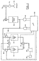
- the apparatus includes at least two beds 10 and 12 which are filled with a physical separation medium or material.
- the separation material selectively adsorbs one or more adsorbable components and passes one or more nonadsorbable components of such a gaseous mixture.
- the physical separation material is a molecular sieve with pores of uniform size and essentially the same molecular dimensions. These pores selectively adsorb molecules in accordance with molecular shape, polarity, degree of saturation, and the like.
- the physical separation medium is an aluminasilicate composition with 4 to 5 ⁇ (Angstrom) pores. More specifically, the molecular sieve is a sodium or calcium form of aluminasilicate, such as type 5A zeolite.
- the aluminasilicate may have a higher silicon-to-aluminum ratio, larger pores, and an affinity for polar molecules, e.g., type 13x zeolite.
- the zeolite adsorbs nitrogen, carbon monoxide, carbon dioxide, water vapor, and other significant components of air.
- a cross-over valving means 20, which preferably includes a four-way valve 21, selectively and cyclically connects the inlet end of two beds, one at a time, during a production phase with a source of the gas mixture, e.g., air under pressure supplied from a compressor 22, while the other bed is vented to atmosphere during a purge phase.
- a source of the gas mixture e.g., air under pressure supplied from a compressor 22
- the cross-over valving means selectively connects one of the beds in fluid communication with an air pump or compressor 22 which supplies air under about 15-30 pounds per square inch.
- fluid communication refers to means allowing flow of the appropriate gases.
- vacuum can also be used during the purge phase with the present invention to enhance evacuation.
- the compressor is connected to a drive motor 23, in the preferred embodiment about a 1 ⁇ 4-horsepower electric motor.
- a solenoid (not shown) or other cross-over valve actuating means selectively causes the cross-over valving means to move alternately between first and second positions.
- the first position illustrated in Fig. 1
- the first bed 10 is connected with the compressor 22 to cause nitrogen adsorption and oxygen enrichment in the product gas
- the second bed 12 is vented to atmosphere to allow evacuation.
- the first bed is vented to atmosphere to allow evacuation and the second bed is connected with the air compressor to cause nitrogen adsorption.
- an adsorption zone of finite, relatively large size is formed.
- This adsorption zone is a region of the bed in which the full capacity of the adsorbent to hold the adsorbable components has not been reached.
- the composition of the gas in the voids of the zeolite varies from substantially pure primary-product gas at the outlet end, to the ambient gaseous mixture composition at the inlet end. This adsorption zone moves from the bed inlet toward a bed outlet with a velocity significantly less than the superficial gas velocity in the bed.
- the breakthrough is defined by the size and configuration of the bed container as well as the packing configuration of the molecular sieve and the flow rate and bed gas pressure.
- the configuration is generally cylindrical, while the output volume rate can vary from about 0 to 6 liters per minute, and more specifically 3, 5, and 6 liters, respectively.
- the breakthrough is the time required for the diffusion reaction as the nitrogen saturates and is weakly bonded to the sieve bed.
- primary product-enriched bed gas in the zeolite voids varies from a higher primary product gas concentration at the bed outlet to a lower concentration at the bed inlet.
- the primary product-enriched bed gas is about 80 percent primary product at breakthrough. While adsorption is occurring in one bed, the adsorbable components adsorbed by the separation medium of the other bed are purged from the other bed because of the drop in pressure due to atmospheric venting and because of exposure to relatively pure product gas from the first bed.
- the first bed 10 is connected with a reservoir or product tank 30 by way of a first check valve 32 or other unidirectional valving means.
- the first check valve 32 permits the primary product gas from the first bed 10 to flow into the reservoir or product tank 30 when product gas pressure in the first bed 10 exceeds the pressure of product gas in the reservoir or product tank 30.
- the first check valve prohibits the product gas from flowing from the reservoir or product tank 30 when the pressure in the first bed 10 is lower than the reservoir or product tank. More specific to the preferred embodiment, the check valve imposes a 1.5 psi bias such that flow is only permitted when the pressure in the first bed exceeds the pressure in the reservoir or product tank by 1.5 psi.
- the second bed 12 is connected with the reservoir or product tank 30 by way of a second check valve 34 or other unidirectional valving means. The second check valve 34 again provides for unidirectional flow of the primary product gas from the second bed 12 to the reservoir or product tank 30.
- a pressure equalization flow path 40 extends between outlets of the first and second beds.
- a concentration equalization valve 42 is either open or closed to selectively permit or prevent gas flow through the flow path between the first and second beds.
- a control means 50 cyclically causes the cross-over valve actuating means (i.e., two solenoids) and the concentration equalization valve 42 to be operated. The control means periodically and cyclically enables a concentration equalization valve actuator which is also a solenoid.
- Oxygen sensor 43 registers the oxygen concentration of the product gas and can be located in the product tank 30.
- the sensor 43 communicates a sensed value to the microprocessor (i.e., control means).
- a pressure sensor 45 registers the pressure in the product tank and communicates the same to the microprocessor.
- the control means causes the cross-over valving means 20 to alternate between its first and second positions for the appropriate period during each cycle segment.
- a cycle segment can be either the product gas generation cycle or the purge cycle.
- the cycle duration is selected such that each bed is connected with the source of air for a duration which is equal to or less than the breakthrough time.
- the mechanism which triggers the cross-over valving can be based on the pressure, such as a pressure set point or set point range, in the bleed line from the product tank as is used in a pressure-based control cycle, or it can be based strictly on a residence time from the product-producing bed, such as in a timing cycle-based control cycle.
- control cycle can utilize variable pressure in order to achieve a residence time within a defined range based upon a projected breakthrough time.
- the beds are 3.5 inches in diameter, 15 inches in length, and each contains 6.5 pounds of 5A zeolite.
- the gas mixture is supplied up to 32 pounds of pressure to the first bed.
- the second bed i.e., a "used" bed
- the concentration equalization valve is opened allowing primary product-enriched gas from the first bed to flow into the evacuated second bed.
- one bed is evacuated and the other has just reached the pressure set point which drives flow between the beds.
- the flow is of high oxygen content so that the first product to pass into the product tank is essentially product gas produced by the oxygen beds.
- the second bed pressure is product-enriched gas to purge the sieve bed.
- the cross-over valving means 20 is actuated to reverse its position. Actuating the cross-over valving means discontinues supplying of the gaseous mixture to the first bed and commences evacuating it and concurrently discontinues evacuating the second bed and commences supplying it with the gaseous mixture.
- the concentration equalization valve 42 remains open to continue allowing a purge supply of product-enriched gas to flow into the second bed. This equalizes the concentration of gas which is supplied to the product tank since the cycling is sequenced so that the product gas proceeds the breakthrough zone to flow into the product tank. Subsequently, the concentration equalization valve closes and terminates the flow of primary-product gas between the beds. In the second segment of the cycle, the pressure in the second bed increases approaching the 32 psi gas mixture source pressure. Concurrently, the pressure in the first bed decreases approaching atmospheric pressure.
- the concentration equalization valve 42 is opened allowing the primary product-enriched gas in the zeolite voids of the second bed to flow to the first bed. While the primary product-enriched gas is flowing to the first bed, the cross-over valving means is actuated. Actuating the cross-over valving means discontinues the evacuation of the first bed and commences supplying the gaseous mixture and concurrently discontinues supplying the gaseous mixture to the second bed and commences evacuating it. Subsequent to actuating the cross-over valving means, the concentration equalization valve is closed terminating the pressure equalizing flow of the primary product-enriched gas between the beds. The steps are cyclically repeated to provide continuing fractionating of the primary product gas from the mixture.
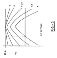
- Fig. 2 illustrates the oxygen concentration of the product gas as it varies with the concentration equalization valve setting. The setting is shown as achieving an optimal oxygen concentration output at a concentration equalization valve setting.
- Figs. 3 and 4 are schematic representations of the control scheme for an oxygen concentrator wherein Fig. 3 illustrates the prior art, and Fig. 4 represents the present invention.
- the concentration equalization flow valve starts at an initial setting, and after a first waiting period which happens to be from about 1 minute to 1 hour, preferably from 2 minutes to 30 minutes, and more preferably from 5 to 12 minutes, the microprocessor will cause a concentration equalization flow valve adjustment means to change one time unit increment.
- Each time unit increment is from about 1 to about 50 milliseconds, more preferably about 10 to 30 milliseconds.
- the closed-loop feedback circuit compares a voltage value from the oxygen corresponding to oxygen output to the last determined value immediately prior to the incremental time unit change.
- the microprocessor causes the concentration equalization valve adjustment means to change an additional time unit increment in the same direction (i.e., directing a longer or shorter flow of output gas into the purging bed).
- the microprocessor will continue this process of incremental time unit adjustment and comparison of the oxygen outflow in the same direction until the circuit senses a drop in the value at which point the circuit will direct the time unit adjustment means to step back one unit to the last optimized setting.
- the reservoir or product tank 30 maintains a reservoir of oxygen at a minimum pressure of about 18 psi.
- the reservoir or product tank is connected with a pressure regulator 70 for controlling the pressure or flow rate of oxygen to the patient.
- a flow meter 72 provides a visual indication of the rate at which the patient is receiving oxygen.
- a humidifier 74 adds moisture to the oxygen primary product to replace the moisture removed by the beds.
- a breathing apparatus 76 assists in delivering the oxygen to the patient.
- Most medical prescriptions require that oxygen be supplied to the patient at the rate of 6 liters per minute or less.
Landscapes
- Chemical & Material Sciences (AREA)
- Health & Medical Sciences (AREA)
- Engineering & Computer Science (AREA)
- Analytical Chemistry (AREA)
- General Chemical & Material Sciences (AREA)
- Oil, Petroleum & Natural Gas (AREA)
- Chemical Kinetics & Catalysis (AREA)
- Emergency Medicine (AREA)
- Biomedical Technology (AREA)
- Anesthesiology (AREA)
- Pulmonology (AREA)
- Heart & Thoracic Surgery (AREA)
- Hematology (AREA)
- Life Sciences & Earth Sciences (AREA)
- Animal Behavior & Ethology (AREA)
- General Health & Medical Sciences (AREA)
- Public Health (AREA)
- Veterinary Medicine (AREA)
- Separation Of Gases By Adsorption (AREA)
- Oxygen, Ozone, And Oxides In General (AREA)
Abstract
Claims (18)
- Procédé de fractionnement d'un premier gaz constitutif et d'un second gaz constitutif et d'optimisation de la concentration dudit premier gaz constitutif par une commande par boucle de rétroaction dans un concentrateur de gaz ayanta) au moins deux lits de fractionnement (10, 12) ayant une extrémité d'entrée et espacée d'une extrémité de sortie, lesdits lits étant chacun en communication de fluide sélective avec l'autre lit à l'extrémité de sortie par un trajet d'écoulement d'égalisation de concentration (40), le flux de gaz dans ledit trajet d'écoulement d'égalisation de concentration étant régulé par une vanne d'égalisation de concentration (42) qui a une pluralité de réglages d'égalisation de la concentration par incréments de temps,b) un moyen de commande électronique (50) qui a un moyen de mémoire en communication fonctionnelle avec ladite vanne d'égalisation de concentration (42) etc) un moyen de capteur (43) pour déterminer une première sortie de concentration de premier gaz constitutif, ledit procédé comprenant les étapes consistant à :i) déterminer une sortie de concentration de premier gaz constitutif ayant une première valeur, d'au moins l'un desdits deux lits de fractionnement grâce audit moyen de capteur (43),ii) mémoriser ladite première valeur dans ledit moyen de mémoire,iii) faire varier, au moyen dudit moyen de commande électronique (50), ladite vanne d'égalisation de concentration (42) pour un autre réglage dans le temps de la vanne par le biais de l'application d'au moins un incrément de temps,iv) déterminer une seconde valeur en mesurant la sortie de concentration du premier gaz constitutif dudit au moins un lit de fractionnement avec ladite vanne d'égalisation de concentration (42) audit second réglage dans le temps de la vanne par le biais dudit moyen de capteur (43),v) mémoriser ladite seconde valeur dans ledit moyen de mémoire,vi) comparer ladite seconde valeur à ladite première valeur et, si elle a augmenté, faire varier ladite vanne d'égalisation de concentration en appliquant au moins un incrément de temps dans le même sens et, si elle a diminué, faire varier ladite vanne d'égalisation de concentration dans le sens opposé de manière à optimiser ladite sortie de concentration de premier gaz constitutif grâce audit moyen de commande électronique (50).
- Procédé de fractionnement de gaz selon la revendication 1, dans lequel les première et seconde valeurs représentent la sortie du premier gaz constitutif des premier et second lits de fractionnement (10, 12) ensemble.
- Procédé de fractionnement de gaz selon la revendication 2, dans lequel ledit moyen de commande électronique (50) est un microprocesseur qui est intégré au concentrateur de gaz.
- Procédé de fractionnement de gaz selon la revendication 2, dans lequel le procédé est répété de façon périodique.
- Procédé de fractionnement de gaz selon la revendication 4, dans lequel il existe un délai d'environ 0,1 à environ 10 minutes entre la détermination de la première valeur et de la seconde valeur, et il existe un intervalle d'environ 0,001 à environ 2 secondes entre le réglage de vanne d'égalisation de concentration.
- Procédé de fractionnement de gaz selon la revendication 5, dans lequel ledit délai est d'environ 1 à 5 minutes entre la détermination de la première valeur et de la seconde valeur, et ledit intervalle est d'environ 0,001 à environ 1 seconde entre le réglage de la vanne d'égalisation de concentration.
- Procédé selon la revendication 1, dans lequel ledit moyen de commande électronique (50) est éloigné dudit concentrateur de gaz.
- Procédé selon la revendication 7, dans lequel ledit moyen de commande électronique (50) est en communication téléphonique avec ledit concentrateur de gaz.
- Procédé selon la revendication 1, dans lequel le réglage de la vanne de concentration est modifié par incrémentation pour faire varier le temps de communication de fluide du premier lit au second lit alors que le temps de communication de fluide du second lit au premier lit reste la même.
- Procédé selon la revendication 9, dans lequel l'incrément de temps de la modification de la communication de fluide est d'environ 1 à 50 millisecondes.
- Procédé selon la revendication 1, dans lequel lesdits réglages par incrémentation de la vanne d'égalisation de concentration se rapportent à la période où le gaz de sortie provenant du second lit circule au travers du trajet d'écoulement d'égalisation de concentration (40) par rapport à la quantité de temps pendant laquelle le gaz de sortie circule depuis le premier lit par le trajet d'écoulement d'égalisation de concentration (40).
- Procédé selon la revendication 11, dans lequel lesdits réglages par incrémentation augmentent la durée pendant laquelle le gaz circule du second lit de fractionnement par le trajet d'écoulement d'égalisation de concentration (40) alors que la durée pendant laquelle le gaz circule depuis le premier lit de fractionnement par le trajet d'écoulement d'égalisation de concentration (40) est maintenue constante.
- Procédé selon la revendication 12, dans lequel lesdits réglages représentent des incréments de temps de 1 à 40 millisecondes.
- Procédé selon la revendication 1, dans lequel ledit premier gaz constitutif est de l'oxygène et ledit second gaz constitutif est de l'air.
- Dispositif de concentrateur de gaz destiné à fractionner un premier gaz constitutif et un second gaz constitutif et à optimiser la concentration dudit premier gaz constitutif par une commande par boucle de rétroaction comprenant :a) au moins deux lits de fractionnement (10, 12) en communication de fluide l'un avec l'autre à l'extrémité de sortie desdits lits par un trajet d'écoulement d'égalisation de concentration (40), une vanne d'égalisation de concentration (42) étant disposée dans ledit trajet d'écoulement d'égalisation de concentration (40) et se voyant appliquer des incréments de temps,b) un moyen de commande électronique (50) relié à ladite vanne d'égalisation de concentration (42) et ayant un moyen de mémoire ainsi qu'un moyen de comparaison de valeurs relatives, etc) un moyen de mesure agencé pour déterminer la sortie dudit premier gaz constitutif d'au moins un des lits de fractionnement (10, 12) et relié audit moyen de commande électronique (50)
agencé pour déterminer une première valeur en mesurant la sortie de concentration en premier gaz constitutif dudit au moins un lit et mémoriser ladite première valeur dans ladite mémoire, et
agencé pour faire varier davantage ladite vanne d'égalisation de concentration par le biais de l'application d'au moins un incrément de temps et
agencé pour déterminer une seconde valeur en mesurant la sortie de concentration en premier gaz constitutif dudit lit et mémoriser ladite seconde valeur dans ledit moyen de mémoire,
ledit moyen de commande électronique (50) est en outre agencé pour comparer lesdites première et seconde valeurs afin de modifier en conséquence le réglage par incrémentation de ladite vanne d'égalisation de concentration (42) pour optimiser ladite sortie de concentration en premier gaz constitutif. - Dispositif selon la revendication 15, dans lequel ledit moyen de commande électronique (50) est constitué d'un microprocesseur en communication avec un électroaimant qui agit sur ladite vanne d'égalisation de concentration (42).
- Dispositif selon la revendication 15, dans lequel ledit moyen de mesure est constitué d'au moins l'un d'un capteur de concentration en oxygène (43) et d'un capteur de pression (45).
- Dispositif selon la revendication 17, dans lequel lesdits au moins deux lits de fractionnement de gaz (10, 12) ont une extrémité de sortie séparée par une zone contenant un milieu de fractionnement d'une extrémité de sortie,lesdits lits (10, 12) sont chacun dans une première communication de fluide sélective avec une source d'alimentation en gaz sous pression (22, 23) et de manière alternée avec une source de chute de pression dans une seconde communication de fluide sélective à l'extrémité de sortie par le biais dudit trajet d'écoulement d'égalisation de concentration (40),une vanne d'interconnexion (21) est disposée dans ladite première communication de fluide sélective et est reliée de façon fonctionnelle audit moyen de commande électronique (50) afin de définir une plage de temps de séjour pendant laquelle le gaz provenant de ladite source d'alimentation en gaz (22, 23) est en contact avec ledit milieu de fractionnement.
Applications Claiming Priority (3)
| Application Number | Priority Date | Filing Date | Title |
|---|---|---|---|
| US873391 | 1997-06-12 | ||
| US08/873,391 US5906672A (en) | 1996-06-14 | 1997-06-12 | Closed-loop feedback control for oxygen concentrator |
| PCT/US1998/011581 WO1998056488A1 (fr) | 1997-06-12 | 1998-06-05 | Commande de reaction en boucle fermee pour concentrateur d'oxygene |
Publications (2)
| Publication Number | Publication Date |
|---|---|
| EP0932439A1 EP0932439A1 (fr) | 1999-08-04 |
| EP0932439B1 true EP0932439B1 (fr) | 2005-10-26 |
Family
ID=25361554
Family Applications (1)
| Application Number | Title | Priority Date | Filing Date |
|---|---|---|---|
| EP98926313A Expired - Lifetime EP0932439B1 (fr) | 1997-06-12 | 1998-06-05 | Commande de reaction en boucle fermee pour concentrateur d'oxygene |
Country Status (6)
| Country | Link |
|---|---|
| US (1) | US5906672A (fr) |
| EP (1) | EP0932439B1 (fr) |
| AU (1) | AU7818098A (fr) |
| CA (1) | CA2262654C (fr) |
| DE (1) | DE69832036T2 (fr) |
| WO (1) | WO1998056488A1 (fr) |
Families Citing this family (88)
| Publication number | Priority date | Publication date | Assignee | Title |
|---|---|---|---|---|
| FR2772637B1 (fr) * | 1997-12-18 | 2000-02-11 | Air Liquide | Procede de separation gazeuse par adsorption avec production a debit variable, notamment pour la production d'oxygene |
| FR2783723B1 (fr) * | 1998-09-25 | 2000-12-29 | Air Liquide | Procede de traitement d'un melange gazeux par adsorption a modulation de pression, a debit variable de production |
| US6346139B1 (en) | 1999-05-12 | 2002-02-12 | Respironics, Inc. | Total delivery oxygen concentration system |
| US6395065B1 (en) * | 1999-05-14 | 2002-05-28 | Respironics, Inc. | Air flow control in a gas fractionalization system and associated method |
| US6348082B1 (en) * | 1999-05-14 | 2002-02-19 | Respironics, Inc. | Gas fractionalization system and associated method |
| US6277174B1 (en) * | 2000-01-07 | 2001-08-21 | Praxair Technology, Inc. | Low pressure ratio VPSA plant tuning and balancing system |
| US6558451B2 (en) * | 2000-05-10 | 2003-05-06 | Airsep Corporation | Multiple bed pressure swing adsorption method and apparatus |
| US6651658B1 (en) * | 2000-08-03 | 2003-11-25 | Sequal Technologies, Inc. | Portable oxygen concentration system and method of using the same |
| US6691702B2 (en) * | 2000-08-03 | 2004-02-17 | Sequal Technologies, Inc. | Portable oxygen concentration system and method of using the same |
| AU2001290679A1 (en) * | 2000-09-06 | 2002-03-22 | Colorado Altitude Training Llc | Altitude simulation method and system |
| US6511526B2 (en) | 2001-01-12 | 2003-01-28 | Vbox, Incorporated | Pressure swing adsorption gas separation method and apparatus |
| GB0123310D0 (en) * | 2001-09-28 | 2001-11-21 | Honeywell Normalair Garrett | Breathing gas supply system |
| CN1223510C (zh) * | 2001-10-30 | 2005-10-19 | 帝人株式会社 | 氧气浓缩装置 |
| JP4473580B2 (ja) * | 2002-01-31 | 2010-06-02 | エアーセップ・コーポレーション | 可搬式酸素濃縮器 |
| US20030230196A1 (en) * | 2002-06-18 | 2003-12-18 | Tai-Jin Kim | Oxygen supply device |
| FR2841153B1 (fr) * | 2002-06-21 | 2004-07-23 | Air Liquide | Procede de regulation d'une unite de traitement, par adsorption a modulation de pression, d'au moins un gaz de charge |
| GB0230098D0 (en) * | 2002-12-24 | 2003-01-29 | Honeywell Normalair Garrett | Method of controlling a gas absorption apparatus |
| US20040211414A1 (en) * | 2003-04-28 | 2004-10-28 | Litton Systems, Inc. | Oxygen concentration system having selectable beds |
| DE10323137B4 (de) * | 2003-05-22 | 2008-04-30 | DRäGER AEROSPACE GMBH | Vorrichtung zur Anreicherung von Luft mit Sauerstoff in einem Flugzeug und einem Verfahren zum Betreiben der Vorrichtung |
| SG128679A1 (en) * | 2003-08-26 | 2007-01-30 | Teijin Pharma Ltd | Oxygen-concentrating device |
| US7438745B2 (en) | 2003-10-07 | 2008-10-21 | Inogen, Inc. | Portable gas fractionalization system |
| US7066985B2 (en) * | 2003-10-07 | 2006-06-27 | Inogen, Inc. | Portable gas fractionalization system |
| US20050072423A1 (en) | 2003-10-07 | 2005-04-07 | Deane Geoffrey Frank | Portable gas fractionalization system |
| US20050072426A1 (en) * | 2003-10-07 | 2005-04-07 | Deane Geoffrey Frank | Portable gas fractionalization system |
| US7135059B2 (en) | 2003-10-07 | 2006-11-14 | Inogen, Inc. | Portable gas fractionalization system |
| DE102004009870B3 (de) * | 2004-02-26 | 2005-10-27 | Fraunhofer-Gesellschaft zur Förderung der angewandten Forschung e.V. | Verfahren und Vorrichtung zur Charakterisierung von OSI-Material |
| DE102004026650B4 (de) * | 2004-06-01 | 2007-11-29 | DRäGER AEROSPACE GMBH | Verfahren zum Betreiben einer Luftzerlegungsanlage zur Gewinnung von Sauerstoff an Bord eines Flugzeugs |
| US7455717B2 (en) | 2004-10-25 | 2008-11-25 | Invacare Corporation | Apparatus and method of providing concentrated product gas |
| US7494521B2 (en) * | 2004-10-26 | 2009-02-24 | Althouse Michael D | Trigger mechanism for dust filter pulse cleaning system |
| US7954490B2 (en) * | 2005-02-09 | 2011-06-07 | Vbox, Incorporated | Method of providing ambulatory oxygen |
| FR2883489B1 (fr) * | 2005-03-25 | 2008-01-11 | Air Liquide | Procede de reglage d'une installation de traitement par adsorption d'un gaz soumis a un ecoulement a travers ladite installation |
| US7722700B2 (en) | 2006-09-18 | 2010-05-25 | Invacare Corporation | Apparatus and method of providing concentrated product gas |
| US7686870B1 (en) | 2005-12-29 | 2010-03-30 | Inogen, Inc. | Expandable product rate portable gas fractionalization system |
| US7875105B2 (en) * | 2006-08-08 | 2011-01-25 | Invacare Corporation | Oxygen concentrator having structural sieve beds |
| US7763103B2 (en) * | 2006-08-28 | 2010-07-27 | Ric Investments, Llc | Oxygen concentration system |
| FR2906160B1 (fr) | 2006-09-25 | 2009-06-05 | Air Liquide | Procede psa a lit d'adsorption composite forme d'un adsorbant et d'agglomerats de mcp |
| NZ603120A (en) * | 2007-04-20 | 2014-01-31 | Invacare Corp | Product gas concentrator and method associated therewith |
| WO2008136540A1 (fr) * | 2007-05-07 | 2008-11-13 | Teijin Pharma Limited | Enrichisseur d'oxygène |
| US20090065007A1 (en) * | 2007-09-06 | 2009-03-12 | Wilkinson William R | Oxygen concentrator apparatus and method |
| US20090205493A1 (en) * | 2008-02-20 | 2009-08-20 | Thompson Loren M | Method of removing water from an inlet region of an oxygen generating system |
| US20090205494A1 (en) * | 2008-02-20 | 2009-08-20 | Mcclain Michael S | Single manifold assembly for oxygen-generating systems |
| US20090211443A1 (en) * | 2008-02-21 | 2009-08-27 | Youngblood James H | Self-serviceable filter for an oxygen generating device |
| US7722698B2 (en) * | 2008-02-21 | 2010-05-25 | Delphi Technologies, Inc. | Method of determining the purity of oxygen present in an oxygen-enriched gas produced from an oxygen delivery system |
| US20090214393A1 (en) * | 2008-02-22 | 2009-08-27 | Chekal Michael P | Method of generating an oxygen-enriched gas for a user |
| US8075676B2 (en) | 2008-02-22 | 2011-12-13 | Oxus America, Inc. | Damping apparatus for scroll compressors for oxygen-generating systems |
| US20090229460A1 (en) * | 2008-03-13 | 2009-09-17 | Mcclain Michael S | System for generating an oxygen-enriched gas |
| US9120050B2 (en) | 2008-04-21 | 2015-09-01 | Invacare Corporation | Product gas concentrator utilizing vacuum swing adsorption and method associated therewith |
| USD606655S1 (en) | 2008-06-27 | 2009-12-22 | Inova Labs, Llc | Portable oxygen concentrator |
| JP5906089B2 (ja) * | 2008-12-22 | 2016-04-20 | コーニンクレッカ フィリップス エヌ ヴェKoninklijke Philips N.V. | 液体酸素製造装置及び方法 |
| WO2011011432A2 (fr) | 2009-07-22 | 2011-01-27 | Vbox, Incorporated | Appareil destiné à séparer l'oxygène de l'air ambiant |
| BR112012006823A2 (pt) | 2009-09-30 | 2019-09-24 | Koninl Philips Electronics Nv | disposição de concentração de gás, sistema de concentração de gás e bomba de gás para bombeamento de gás |
| US10821243B2 (en) | 2010-04-13 | 2020-11-03 | Advanced Interactive Response Systems, LLC | Gas supply warning and communication system |
| US11511062B2 (en) | 2010-04-13 | 2022-11-29 | Advanced Interactive Response Systems LLC | Gas supply warning and communication system |
| US9714860B2 (en) * | 2010-04-13 | 2017-07-25 | Advanced Interactive Response Systems | Gas supply warning and communication system |
| US20110315140A1 (en) * | 2010-06-29 | 2011-12-29 | Precision Medical, Inc. | Portable oxygen concentrator |
| US8616207B2 (en) | 2010-09-07 | 2013-12-31 | Inova Labs, Inc. | Oxygen concentrator heat management system and method |
| US20120055474A1 (en) | 2010-09-07 | 2012-03-08 | Wilkinson William R | Methods and systems for providing oxygen enriched gas |
| EP2694188B1 (fr) | 2011-04-08 | 2017-06-21 | L'Air Liquide Société Anonyme pour l'Etude et l'Exploitation des Procédés Georges Claude | Mélange d'un adsorbant et d'un matériau à changement de phase à densité adaptée |
| US8758480B2 (en) * | 2011-09-09 | 2014-06-24 | Torosoleil, Llc | Dynamic and continuous control for pressure swing adsorption |
| EP2809949A4 (fr) | 2012-02-03 | 2015-12-09 | Invacare Corp | Dispositif de pompage |
| US9266053B2 (en) | 2012-06-18 | 2016-02-23 | Invacare Corporation | System and method for concentrating gas |
| US9067174B2 (en) | 2012-03-09 | 2015-06-30 | Invacare Corporation | System and method for concentrating gas |
| NZ631712A (en) | 2012-03-09 | 2016-08-26 | Invacare Corp | System and method for concentrating gas by adsorption |
| TWI590847B (zh) * | 2012-09-20 | 2017-07-11 | Teijin Pharma Ltd | Oxygen concentration device |
| WO2014059409A1 (fr) | 2012-10-12 | 2014-04-17 | Inova Labs, Inc. | Systèmes de concentrateur d'oxygène et procédés associés |
| JP6321663B2 (ja) | 2012-10-12 | 2018-05-09 | イノヴァ ラボ,インコーポレイテッド | 酸素富化ガス送達のための方法およびシステム |
| WO2014059408A1 (fr) | 2012-10-12 | 2014-04-17 | Inova Labs, Inc. | Systèmes de concentrateur d'oxygène double et procédés associés |
| US9061238B2 (en) | 2013-03-15 | 2015-06-23 | Invacare Corporation | Gas concentrator |
| JP6604950B2 (ja) * | 2013-12-20 | 2019-11-13 | コーニンクレッカ フィリップス エヌ ヴェ | 急速診断を備える酸素分離器 |
| US9440179B2 (en) | 2014-02-14 | 2016-09-13 | InovaLabs, LLC | Oxygen concentrator pump systems and methods |
| US11247015B2 (en) | 2015-03-24 | 2022-02-15 | Ventec Life Systems, Inc. | Ventilator with integrated oxygen production |
| US10245406B2 (en) | 2015-03-24 | 2019-04-02 | Ventec Life Systems, Inc. | Ventilator with integrated oxygen production |
| CN105727685B (zh) * | 2016-04-22 | 2018-06-29 | 莱芜钢铁集团电子有限公司 | 一种分子筛空气再生阀的自动控制方法及装置 |
| US11458274B2 (en) | 2016-05-03 | 2022-10-04 | Inova Labs, Inc. | Method and systems for the delivery of oxygen enriched gas |
| US10773049B2 (en) | 2016-06-21 | 2020-09-15 | Ventec Life Systems, Inc. | Cough-assist systems with humidifier bypass |
| US10894139B2 (en) * | 2018-01-19 | 2021-01-19 | Ergo-Flex Technologies, LLC | Oxygen treatment device for mammals |
| WO2019221852A1 (fr) | 2018-05-13 | 2019-11-21 | Ahmad Samir Saleh | Système portable de ventilateur médical utilisant des concentrateurs portables d'oxygène |
| US11442437B2 (en) | 2018-06-20 | 2022-09-13 | Lehigh University | Multivariable model predictive controller |
| WO2020242825A1 (fr) | 2019-05-28 | 2020-12-03 | Invacare Corporation | Système et procédé de concentration de gaz |
| DE102020116514B4 (de) | 2020-06-23 | 2025-08-21 | Krinner Drucklufttechnik Gmbh | Vorrichtung und verfahren zur atemlufterzeugung |
| JP2023534034A (ja) | 2020-07-16 | 2023-08-07 | インバケア コーポレイション | ガスを濃縮するためのシステムおよび方法 |
| JP7414355B2 (ja) | 2020-07-16 | 2024-01-16 | ベンテック ライフ システムズ, インコーポレイテッド | ガスを濃縮するためのシステムおよび方法 |
| CN116322936B (zh) | 2020-07-16 | 2026-01-09 | 英瓦卡尔公司 | 用于浓缩气体的系统和方法 |
| EP4204055A4 (fr) | 2020-07-16 | 2024-07-31 | Ventec Life Systems, Inc. | Système et procédé pour concentrer un gaz |
| EP4240456A4 (fr) | 2020-11-06 | 2024-09-04 | Ventec Life Systems, Inc. | Systèmes, dispositifs et procédés de gestion de données de thérapie respiratoire |
| US12440634B2 (en) | 2020-12-21 | 2025-10-14 | Ventec Life Systems, Inc. | Ventilator systems with integrated oxygen delivery, and associated devices and methods |
| US12347555B2 (en) | 2021-07-15 | 2025-07-01 | Ventec Life Systems, Inc. | System and method for medical device communication |
| WO2024234041A1 (fr) * | 2023-05-17 | 2024-11-21 | Paritosh Wadekar | Système d'adsorption modulée en pression |
Family Cites Families (37)
| Publication number | Priority date | Publication date | Assignee | Title |
|---|---|---|---|---|
| US2944627A (en) * | 1958-02-12 | 1960-07-12 | Exxon Research Engineering Co | Method and apparatus for fractionating gaseous mixtures by adsorption |
| NL286634A (fr) * | 1961-12-18 | 1900-01-01 | ||
| US3313091A (en) * | 1963-11-04 | 1967-04-11 | Exxon Research Engineering Co | Vacuum cycle adsorption |
| US3280536A (en) * | 1963-07-30 | 1966-10-25 | Exxon Research Engineering Co | Method for providing an oxygen-enriched environment |
| US4222750A (en) * | 1976-08-16 | 1980-09-16 | Champion Spark Plug Company | Oxygen enrichment system for medical use |
| US4263018A (en) * | 1978-02-01 | 1981-04-21 | Greene & Kellogg | Pressure swing adsorption process and system for gas separation |
| US4247311A (en) * | 1978-10-26 | 1981-01-27 | Pall Corporation | Downflow or upflow adsorbent fractionator flow control system |
| FR2455765A1 (fr) * | 1979-05-02 | 1980-11-28 | Intertechnique Sa | Dispositif regulateur d'alimentation en gaz d'un organe recepteur |
| US4259548A (en) * | 1979-11-14 | 1981-03-31 | Gte Products Corporation | Apparatus for monitoring and signalling system |
| US4459266A (en) * | 1982-01-05 | 1984-07-10 | Lamoreaux Charles L | Air purity monitoring system |
| US4648888A (en) * | 1982-07-09 | 1987-03-10 | Hudson Oxygen Therapy Sales Co. | Oxygen concentrator |
| US4516424A (en) * | 1982-07-09 | 1985-05-14 | Hudson Oxygen Therapy Sales Company | Oxygen concentrator monitor and regulation assembly |
| US4627860A (en) * | 1982-07-09 | 1986-12-09 | Hudson Oxygen Therapy Sales Company | Oxygen concentrator and test apparatus |
| US4576616A (en) * | 1982-07-27 | 1986-03-18 | Proto-Med. Inc. | Method and apparatus for concentrating oxygen |
| US4472177A (en) * | 1982-09-09 | 1984-09-18 | Air Products And Chemicals, Inc. | Control system and method for air fractionation by vacuum swing adsorption |
| US4449990A (en) * | 1982-09-10 | 1984-05-22 | Invacare Respiratory Corp. | Method and apparatus for fractioning oxygen |
| DE3672510D1 (de) * | 1985-02-22 | 1990-08-16 | Normalair Garrett Ltd | Pneumatischer partialdrucksensor. |
| CA1297298C (fr) * | 1986-09-22 | 1992-03-17 | Akira Kato | Instrument d'enrichissement des gaz par augmentation de l'oxygene, avec fonction de regulation de la teneur en oxygene du gaz enrichi |
| JPS63307101A (ja) * | 1987-06-05 | 1988-12-14 | Kobe Steel Ltd | 圧力スイング吸着式酸素製造方法 |
| JPH01104327A (ja) * | 1987-10-17 | 1989-04-21 | Tokico Ltd | 気体分離装置 |
| JP2653698B2 (ja) * | 1989-05-19 | 1997-09-17 | トキコ株式会社 | 気体分離装置 |
| JPH0321317A (ja) * | 1989-06-16 | 1991-01-30 | Tokico Ltd | 気体分離装置 |
| US5071453A (en) * | 1989-09-28 | 1991-12-10 | Litton Systems, Inc. | Oxygen concentrator with pressure booster and oxygen concentration monitoring |
| JPH04187210A (ja) * | 1990-11-20 | 1992-07-03 | Tokico Ltd | 気体分離装置 |
| US5247826B1 (en) * | 1992-11-12 | 1995-07-18 | Devilbiss Health Care Inc | Gas concentration and/or flow sensor |
| GB2273252B (en) * | 1992-12-09 | 1996-09-18 | Boc Group Plc | The separation of gaseous mixtures |
| EP0609620B1 (fr) * | 1993-01-30 | 1999-02-10 | The BOC Group plc | Séparation de gaz |
| US5340381A (en) * | 1993-05-17 | 1994-08-23 | Vorih Marc L | Operating system for dual-sieve oxygen concentrators |
| US5407465A (en) * | 1993-12-16 | 1995-04-18 | Praxair Technology, Inc. | Tuning of vacuum pressure swing adsorption systems |
| US5474595A (en) * | 1994-04-25 | 1995-12-12 | Airsep Corporation | Capacity control system for pressure swing adsorption apparatus and associated method |
| US5469372A (en) * | 1994-08-29 | 1995-11-21 | Raymond A. McBrearty | Oxygen concentrator remote monitoring apparatus |
| US5593478A (en) * | 1994-09-28 | 1997-01-14 | Sequal Technologies, Inc. | Fluid fractionator |
| US5531807A (en) * | 1994-11-30 | 1996-07-02 | Airsep Corporation | Apparatus and method for supplying oxygen to passengers on board aircraft |
| US5529607A (en) * | 1995-03-15 | 1996-06-25 | The Boc Group, Inc. | PSA process with dynamic purge control |
| US5627323A (en) * | 1995-05-25 | 1997-05-06 | Stern; Michael | Ultrasonic binary gas measuring device |
| JP3021317U (ja) | 1995-08-04 | 1996-02-20 | 勇一 津田 | 群体珊瑚のスライス面を表に出した壁下地用板 |
| DE29605889U1 (de) * | 1996-03-29 | 1996-06-20 | Kröber Medizintechnik GmbH, 56332 Dieblich | Vorrichtung zur Erzeugung von mit Sauerstoff angereicherter Luft |
-
1997
- 1997-06-12 US US08/873,391 patent/US5906672A/en not_active Expired - Lifetime
-
1998
- 1998-06-05 CA CA002262654A patent/CA2262654C/fr not_active Expired - Fee Related
- 1998-06-05 WO PCT/US1998/011581 patent/WO1998056488A1/fr not_active Ceased
- 1998-06-05 EP EP98926313A patent/EP0932439B1/fr not_active Expired - Lifetime
- 1998-06-05 DE DE69832036T patent/DE69832036T2/de not_active Expired - Lifetime
- 1998-06-05 AU AU78180/98A patent/AU7818098A/en not_active Abandoned
Also Published As
| Publication number | Publication date |
|---|---|
| EP0932439A1 (fr) | 1999-08-04 |
| WO1998056488A1 (fr) | 1998-12-17 |
| DE69832036T2 (de) | 2006-07-13 |
| US5906672A (en) | 1999-05-25 |
| CA2262654C (fr) | 2003-10-28 |
| CA2262654A1 (fr) | 1998-12-17 |
| DE69832036D1 (de) | 2005-12-01 |
| AU7818098A (en) | 1998-12-30 |
Similar Documents
| Publication | Publication Date | Title |
|---|---|---|
| US5906672A (en) | Closed-loop feedback control for oxygen concentrator | |
| CA2262689C (fr) | Capteur de concentration de gaz et commande pour concentrateur d'oxygene utilisant ce capteur | |
| US6551384B1 (en) | Medical oxygen concentrator | |
| US7704304B2 (en) | Process and apparatus for generating and delivering an enriched gas fraction | |
| EP0458350B1 (fr) | ContrÔle amélioré des opérations d'adsorption de pression alternée | |
| US4194890A (en) | Pressure swing adsorption process and system for gas separation | |
| EP2065067B1 (fr) | Concentrateur d'oxygène | |
| US6558451B2 (en) | Multiple bed pressure swing adsorption method and apparatus | |
| US4263018A (en) | Pressure swing adsorption process and system for gas separation | |
| US6245127B1 (en) | Pressure swing adsorption process and apparatus | |
| US7105038B2 (en) | Gas concentration method and its apparatus | |
| US5704964A (en) | Pressure swing adsorption process | |
| US4648888A (en) | Oxygen concentrator | |
| JP2010502299A (ja) | 酸素濃縮システム | |
| US9649589B2 (en) | Oxygen concentrator system and method | |
| US12357939B2 (en) | Method for regulating a unit for separating a gas stream | |
| JPH10194708A (ja) | 酸素濃縮装置 | |
| HK1131077B (en) | Oxygen concentrator |
Legal Events
| Date | Code | Title | Description |
|---|---|---|---|
| PUAI | Public reference made under article 153(3) epc to a published international application that has entered the european phase |
Free format text: ORIGINAL CODE: 0009012 |
|
| 17P | Request for examination filed |
Effective date: 19990202 |
|
| AK | Designated contracting states |
Kind code of ref document: A1 Designated state(s): DE FR GB SE |
|
| 17Q | First examination report despatched |
Effective date: 20001120 |
|
| GRAP | Despatch of communication of intention to grant a patent |
Free format text: ORIGINAL CODE: EPIDOSNIGR1 |
|
| GRAS | Grant fee paid |
Free format text: ORIGINAL CODE: EPIDOSNIGR3 |
|
| GRAA | (expected) grant |
Free format text: ORIGINAL CODE: 0009210 |
|
| AK | Designated contracting states |
Kind code of ref document: B1 Designated state(s): DE FR GB SE |
|
| REG | Reference to a national code |
Ref country code: GB Ref legal event code: FG4D |
|
| REF | Corresponds to: |
Ref document number: 69832036 Country of ref document: DE Date of ref document: 20051201 Kind code of ref document: P |
|
| PG25 | Lapsed in a contracting state [announced via postgrant information from national office to epo] |
Ref country code: SE Free format text: LAPSE BECAUSE OF FAILURE TO SUBMIT A TRANSLATION OF THE DESCRIPTION OR TO PAY THE FEE WITHIN THE PRESCRIBED TIME-LIMIT Effective date: 20060126 |
|
| ET | Fr: translation filed | ||
| PLBE | No opposition filed within time limit |
Free format text: ORIGINAL CODE: 0009261 |
|
| STAA | Information on the status of an ep patent application or granted ep patent |
Free format text: STATUS: NO OPPOSITION FILED WITHIN TIME LIMIT |
|
| 26N | No opposition filed |
Effective date: 20060727 |
|
| REG | Reference to a national code |
Ref country code: DE Ref legal event code: R082 Ref document number: 69832036 Country of ref document: DE Representative=s name: MEHLER ACHLER PATENTANWAELTE PARTNERSCHAFT MBB, DE Ref country code: DE Ref legal event code: R082 Ref document number: 69832036 Country of ref document: DE Representative=s name: MEHLER ACHLER PATENTANWAELTE, DE |
|
| REG | Reference to a national code |
Ref country code: FR Ref legal event code: PLFP Year of fee payment: 19 |
|
| PGFP | Annual fee paid to national office [announced via postgrant information from national office to epo] |
Ref country code: GB Payment date: 20160627 Year of fee payment: 19 |
|
| PGFP | Annual fee paid to national office [announced via postgrant information from national office to epo] |
Ref country code: FR Payment date: 20160628 Year of fee payment: 19 |
|
| PGFP | Annual fee paid to national office [announced via postgrant information from national office to epo] |
Ref country code: DE Payment date: 20160628 Year of fee payment: 19 |
|
| REG | Reference to a national code |
Ref country code: DE Ref legal event code: R119 Ref document number: 69832036 Country of ref document: DE |
|
| GBPC | Gb: european patent ceased through non-payment of renewal fee |
Effective date: 20170605 |
|
| REG | Reference to a national code |
Ref country code: FR Ref legal event code: ST Effective date: 20180228 |
|
| PG25 | Lapsed in a contracting state [announced via postgrant information from national office to epo] |
Ref country code: DE Free format text: LAPSE BECAUSE OF NON-PAYMENT OF DUE FEES Effective date: 20180103 Ref country code: GB Free format text: LAPSE BECAUSE OF NON-PAYMENT OF DUE FEES Effective date: 20170605 |
|
| PG25 | Lapsed in a contracting state [announced via postgrant information from national office to epo] |
Ref country code: FR Free format text: LAPSE BECAUSE OF NON-PAYMENT OF DUE FEES Effective date: 20170630 |