EP0932454B1 - Machine de criblage a vibrations amelioree - Google Patents
Machine de criblage a vibrations amelioree Download PDFInfo
- Publication number
- EP0932454B1 EP0932454B1 EP97909424A EP97909424A EP0932454B1 EP 0932454 B1 EP0932454 B1 EP 0932454B1 EP 97909424 A EP97909424 A EP 97909424A EP 97909424 A EP97909424 A EP 97909424A EP 0932454 B1 EP0932454 B1 EP 0932454B1
- Authority
- EP
- European Patent Office
- Prior art keywords
- basket
- screen
- screening machine
- vibratory screening
- centre
- Prior art date
- Legal status (The legal status is an assumption and is not a legal conclusion. Google has not performed a legal analysis and makes no representation as to the accuracy of the status listed.)
- Expired - Lifetime
Links
- 238000012216 screening Methods 0.000 title claims description 31
- 230000005484 gravity Effects 0.000 claims description 35
- 230000009471 action Effects 0.000 claims description 18
- 239000007787 solid Substances 0.000 claims description 18
- 239000004744 fabric Substances 0.000 claims description 11
- 239000011343 solid material Substances 0.000 claims description 8
- 230000001154 acute effect Effects 0.000 claims description 5
- 230000008878 coupling Effects 0.000 claims description 5
- 238000010168 coupling process Methods 0.000 claims description 5
- 238000005859 coupling reaction Methods 0.000 claims description 5
- 238000011068 loading method Methods 0.000 claims description 4
- 238000004519 manufacturing process Methods 0.000 claims description 2
- 238000004140 cleaning Methods 0.000 claims 1
- 239000007788 liquid Substances 0.000 description 15
- 239000000463 material Substances 0.000 description 10
- 239000011236 particulate material Substances 0.000 description 10
- 239000012530 fluid Substances 0.000 description 9
- 238000005553 drilling Methods 0.000 description 7
- 239000002002 slurry Substances 0.000 description 7
- 238000001914 filtration Methods 0.000 description 5
- 238000005304 joining Methods 0.000 description 5
- 239000000203 mixture Substances 0.000 description 5
- 238000000926 separation method Methods 0.000 description 4
- 238000013461 design Methods 0.000 description 3
- 239000002245 particle Substances 0.000 description 3
- 239000004033 plastic Substances 0.000 description 3
- 229920003023 plastic Polymers 0.000 description 3
- 238000005520 cutting process Methods 0.000 description 2
- 230000000694 effects Effects 0.000 description 2
- 229920001971 elastomer Polymers 0.000 description 2
- 239000007789 gas Substances 0.000 description 2
- 239000002184 metal Substances 0.000 description 2
- 238000000034 method Methods 0.000 description 2
- 230000005012 migration Effects 0.000 description 2
- 238000013508 migration Methods 0.000 description 2
- 230000008569 process Effects 0.000 description 2
- 238000012545 processing Methods 0.000 description 2
- 239000005060 rubber Substances 0.000 description 2
- 230000008901 benefit Effects 0.000 description 1
- 230000008859 change Effects 0.000 description 1
- 239000002131 composite material Substances 0.000 description 1
- 238000010276 construction Methods 0.000 description 1
- 230000003628 erosive effect Effects 0.000 description 1
- 230000002706 hydrostatic effect Effects 0.000 description 1
- 239000011344 liquid material Substances 0.000 description 1
- 239000007791 liquid phase Substances 0.000 description 1
- 230000003534 oscillatory effect Effects 0.000 description 1
- 239000012071 phase Substances 0.000 description 1
- 239000002990 reinforced plastic Substances 0.000 description 1
- 230000004044 response Effects 0.000 description 1
- 238000007873 sieving Methods 0.000 description 1
Images

Classifications
-
- B—PERFORMING OPERATIONS; TRANSPORTING
- B07—SEPARATING SOLIDS FROM SOLIDS; SORTING
- B07B—SEPARATING SOLIDS FROM SOLIDS BY SIEVING, SCREENING, SIFTING OR BY USING GAS CURRENTS; SEPARATING BY OTHER DRY METHODS APPLICABLE TO BULK MATERIAL, e.g. LOOSE ARTICLES FIT TO BE HANDLED LIKE BULK MATERIAL
- B07B1/00—Sieving, screening, sifting, or sorting solid materials using networks, gratings, grids, or the like
- B07B1/46—Constructional details of screens in general; Cleaning or heating of screens
-
- B—PERFORMING OPERATIONS; TRANSPORTING
- B01—PHYSICAL OR CHEMICAL PROCESSES OR APPARATUS IN GENERAL
- B01D—SEPARATION
- B01D33/00—Filters with filtering elements which move during the filtering operation
- B01D33/01—Filters with filtering elements which move during the filtering operation with translationally moving filtering elements, e.g. pistons
- B01D33/03—Filters with filtering elements which move during the filtering operation with translationally moving filtering elements, e.g. pistons with vibrating filter elements
- B01D33/0346—Filters with filtering elements which move during the filtering operation with translationally moving filtering elements, e.g. pistons with vibrating filter elements with flat filtering elements
-
- B—PERFORMING OPERATIONS; TRANSPORTING
- B01—PHYSICAL OR CHEMICAL PROCESSES OR APPARATUS IN GENERAL
- B01D—SEPARATION
- B01D33/00—Filters with filtering elements which move during the filtering operation
- B01D33/35—Filters with filtering elements which move during the filtering operation with multiple filtering elements characterised by their mutual disposition
- B01D33/41—Filters with filtering elements which move during the filtering operation with multiple filtering elements characterised by their mutual disposition in series connection
-
- B—PERFORMING OPERATIONS; TRANSPORTING
- B01—PHYSICAL OR CHEMICAL PROCESSES OR APPARATUS IN GENERAL
- B01D—SEPARATION
- B01D33/00—Filters with filtering elements which move during the filtering operation
- B01D33/70—Filters with filtering elements which move during the filtering operation having feed or discharge devices
- B01D33/76—Filters with filtering elements which move during the filtering operation having feed or discharge devices for discharging the filter cake, e.g. chutes
-
- B—PERFORMING OPERATIONS; TRANSPORTING
- B01—PHYSICAL OR CHEMICAL PROCESSES OR APPARATUS IN GENERAL
- B01D—SEPARATION
- B01D33/00—Filters with filtering elements which move during the filtering operation
- B01D33/70—Filters with filtering elements which move during the filtering operation having feed or discharge devices
- B01D33/76—Filters with filtering elements which move during the filtering operation having feed or discharge devices for discharging the filter cake, e.g. chutes
- B01D33/763—Filters with filtering elements which move during the filtering operation having feed or discharge devices for discharging the filter cake, e.g. chutes for continuously discharging concentrated liquid
-
- B—PERFORMING OPERATIONS; TRANSPORTING
- B07—SEPARATING SOLIDS FROM SOLIDS; SORTING
- B07B—SEPARATING SOLIDS FROM SOLIDS BY SIEVING, SCREENING, SIFTING OR BY USING GAS CURRENTS; SEPARATING BY OTHER DRY METHODS APPLICABLE TO BULK MATERIAL, e.g. LOOSE ARTICLES FIT TO BE HANDLED LIKE BULK MATERIAL
- B07B1/00—Sieving, screening, sifting, or sorting solid materials using networks, gratings, grids, or the like
- B07B1/28—Moving screens not otherwise provided for, e.g. swinging, reciprocating, rocking, tilting or wobbling screens
- B07B1/284—Moving screens not otherwise provided for, e.g. swinging, reciprocating, rocking, tilting or wobbling screens with unbalanced weights
-
- B—PERFORMING OPERATIONS; TRANSPORTING
- B07—SEPARATING SOLIDS FROM SOLIDS; SORTING
- B07B—SEPARATING SOLIDS FROM SOLIDS BY SIEVING, SCREENING, SIFTING OR BY USING GAS CURRENTS; SEPARATING BY OTHER DRY METHODS APPLICABLE TO BULK MATERIAL, e.g. LOOSE ARTICLES FIT TO BE HANDLED LIKE BULK MATERIAL
- B07B1/00—Sieving, screening, sifting, or sorting solid materials using networks, gratings, grids, or the like
- B07B1/42—Drive mechanisms, regulating or controlling devices, or balancing devices, specially adapted for screens
Definitions
- This invention relates to vibratory screening machines such as shale shakers used to separate mixtures of solids and liquids into the separate components such as mixtures which result from drilling of a bore hole or tunnel when a drilling fluid is used. Separation of the components permits re-use of the drilling fluid.
- vibratory screening machines such as shale shakers used to separate mixtures of solids and liquids into the separate components such as mixtures which result from drilling of a bore hole or tunnel when a drilling fluid is used. Separation of the components permits re-use of the drilling fluid.
- Such machines which essentially comprise a rigid supporting framework within which is resiliently mounted a box or basket containing one or more mesh screens onto which the mixture of solids and liquids is poured.
- a box or basket containing one or more mesh screens onto which the mixture of solids and liquids is poured.
- vibrate the box or basket so that the solid matter on the mesh screens is itself caused to vibrate. This causes clumps of fine material to break up, and if appropriate, pass through the mesh, together with the liquids, and for larger pieces of material which cannot pass through a mesh to migrate over the surface of the mesh to form part of the solids output of the machine.
- US Patent 4,167,478 describes a modular screening machine having at least one screen for separating particulate material according to size in which the screen box is driven so as to describe an elliptical movement at one end and a substantially rectilinear oscillatory movement at the other end.
- US Patent 4,340,469 also describes a vibrating screening apparatus containing two screens which are vertically spaced above and below two independently rotatable shafts containing unbalanced weights so that when rotated the screen assembly is caused to move in a generally elliptical path.
- the objective is twofold.
- the material has to be vibrated so as to separate liquid from solids as far as possible, and to separate small solids from larger solids particularly where a degree of adhesion can exist as a result of the inherent characteristics of the materials concerned.
- the present invention seeks to provide a simple and expedient solution by providing an improved vibratory drive and filter basket constructions for a sieve particularly a shale shaker as aforesaid, to obtain a high consistency in the ratio of solids transported therethrough.
- the invention provides an improved form of such a machine which is more suitable for real time control using closed loop feedback systems for optimising filtering and throughput.
- the invention also provides an improved shale shaker which can be used as a basic unit or in conjunction with other similar units to provide for greater throughput, and to permit a reliable and controllable screening of mixtures of solids and liquids, with or without real time closed loop feedback control.
- a vibratory screening machine having a rigid housing within which is resiliently mounted a rigid screening basket having upper and lower screens mounted therein and drive means for vibrating the basket relative to the housing which comprises a pair of counter-rotating masses mounted for rotation about two spaced apart parallel axes between the sides of the housing, characterised in that:
- each mass comprises a pair of similar weights which are mounted on opposite sides of a drive unit therefor and the drive and weights are located on a bridge which spans the basket.
- the position of the assembly of weights in the drives relative to the basket may be selected to advantage so that the angle of the major axis of the elliptical motion, which tends to act through the centre of gravity of the basket, subtends an acute angle in an upward sense relative to the lower inclined screen.
- screen is intended to mean a single framed member having a woven wire mesh filtering panel tensioned thereacross or an assembly of such framed members, arranged in edge abutting relation to form a larger area for filtering more material.
- the inclined lower screen reduces the velocity of the smaller particles so as to increase their dwell time on the screen and resultant dewatering.
- the inclination of the lower screen also provides a hydrostatic head of liquid over the screening surface, which has been found to improve the efficiency of separation and volumetric throughput.
- the inclined screen also guarantees that its surface remains flooded with liquid at all times during operation, which is important to ensure efficient separation and transport.
- the lower screen is preferably adapted to be self-clearing so as to reduce the risk of fines becoming permanently lodged between the interstices of the smaller mesh used on the lower screen.
- the lower screen is preferably one which includes two screen cloths one laid above the other over a rigid frame, and which are pretensioned during manufacture so that the tension in the lower cloth is greater than the tension in the upper cloth. Any component of motion perpendicular to the plane of the two cloths forming the lower screen will tend to cause the less tensioned cloth to rise and fall relative to the lower cloth, and the relative movement, and particularly the impact between the cloths during such vibration, will tend to dislodge particulate material from the cloth and prevent particulate material from lodging and blinding the screen.
- Centre of Action will then describe a generally linear motion substantially perpendicular to the plane containing the two parallel axes of rotation.
- the amplitude of the basket movement from its mean position will be limited inter alia by the stiffness of the basket mounting to the frame.
- the basket is preferably mounted on four helical springs which support the weight of the basket and are adapted to vibrate substantially freely with small amplitudes of up to a few millimeters relative to the rigid housing.
- the major axis of the ellipse will be generally perpendicular to the plane containing the two axes of rotation and the minor axis of the ellipse will be generally parallel to that plane if the centre of gravity of the basket coincides with the Centre of Action.
- the basket dead-weight unladen is in the range 1000-1750Kg
- a typical dynamic loading of slurry is in the range 450-700Kg
- a first eccentric weight has a mass of 43Kg and the centre of gravity of the mass is some 40mm from the shaft centre line
- the second eccentric weight has a mass of 26Kg and its centre of gravity is some 47mm from its shaft centre line
- the rotational speed is such as to produce vibration in the range 20-40Hz, preferably in the range 2 5 -33Hz.
- the rigid housing Preferably opposite sides of the rigid housing are parallel and upright when the machine is mounted for use, and nothing protrudes laterally of the frame rigid housing.
- the machines can be placed side by side in close proximity to allow outgoing solids and liquids to be collected by troughs/conveyors adjacent the output ends of the side-by-side machines, and the slurry input to the machines can be discharged into one or two or more of the machines, depending on the volume of slurry to be handled and the capability of the machines to handle the input material.
- each mass or weight along each axis can be divided into two or more (preferably similar) weights, each eccentrically mounted about the same axis.
- the invention also extends to a vibratory screening machine comprising a basket having an inclined screen, drive means for vibrating the basket to cause solid material deposited on the screen to migrate therealong up the incline to the upper discharge end of the screen from which the solid material is discharged, wherein the drive means exerts on the basket a resultant force along a line which passes through or near the centre of gravity of the basket when the latter is unloaded, and wherein the inclination of the screen is such that the centre of gravity of the basket continues to lie on or near the said line for different loadings of the basket.
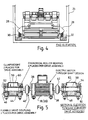
- a vibratory basket designated 10 is spanned by a bridge 12 (see Figure 3) on which are carried two rotational drives 14 and 16.
- Each of the drives comprises a central electric motor 18, (20) of so-called through-shaft design, having an output shaft protruding axially therefrom on opposite sides of the motor casing, and two equal eccentric "in phase” clump weights, are mounted on each rotating output shaft, so that rotation of the motor and the clump weights produces a rotating force equivalent to the clump weights and their eccentricity.
- the drives are shown in more detail in Figure 5 and will be described more fully with reference thereto.
- the basket 10 is supported on helical springs below four brackets 22, 24, 26, 28. Two of the springs can be seen in Figure 4 and are designated by reference numerals 30 and 32.
- Figure 4 also shows the housing 34 within which the basket is carried on the springs and it will be seen that the two sides of the housing 34 are uncluttered and have no protruding elements, so that two or more such housings can be abutted laterally against one another frame, side by side. This allows for variations in material feed rate to be more accommodated, by conveying slurry to one, or two or more units (if more than two units are mounted side by side), depending on the volume of slurry to be processed, by means of a transversely extending duct over the input ends of the units.
- FIG. 5 shows in more detail one of the drive units 16, based on the motor 18.
- the motor is a through shaft motor and an output shaft extends therefrom on both sides of the motor housing at 36 and 38 respectively.
- Each output shaft is connected to a flexible drive coupling 40, 42 respectively, the output shafts of which are carried in journal bearings 44, 46 (in the case of coupling 40) and 48, 50 (in the case of coupling 42).
- Each journal bearing typically comprises a cylindrical roller bearing.
- Mounted on the coupling output shaft 52, 54 are eccentric clump weights 56, 58 respectively. Rotation of the motor 18 causes both clump weights to be similarly rotated and their eccentricity generates a rotating out of balance force as they rotate.
- the clump weights and flexible drives are contained within cylindrical housings 60, 62 respectively.
- the inboard ends of the housing 60, 62 are coupled to the casing of the motor 18 and are closed at their outboard ends.
- the housings 60, 62 each have feet (64, 66, 68, 70 in the case of housing 60) by which the housings are secured to the bridge 12.
- the basket 10 is formed from two side panels 72, 74 between which extend hollow cylindrical tubes 76, 78, 80, 82, 84 and 86. These are welded to the two opposed side panels 72, 74 and create a lightweight, very strong rigid structure.
- Screen supporting rails (not identified in the drawings) support an upper generally horizontal screen 88 and an inclined lower screen 90, which rises in the direction in which particulate material migrates over its surface during vibration, ie from left to right in Figure 2.
- a deflector plate or intermediate screen 92 extends over the lower inclined screen below the region onto which slurry (drilling mud) is poured.
- a collector 94 is located below the discharge end 96 of the lower conveyor.
- clump weights of drive 14 are rotated in the opposite sense to the clump weights of drive 16.
- the motors 18 and 20 may be electric motors, but in combinations where flammable gases or liquid are involved, the motors are more preferably hydraulic or pneumatically powered.
- the springs such as 30, 32 may be replaced by blocks of rubber or plastics, or rubber and plastics composite material.
- the screens for filtering fluids from solids may be formed from rigid metal, or plastics, or metal reinforced plastic frames having stretched and tensioned and bonded thereto woven wire cloths.
- each screen has two layers of wirecloth affixed thereto, and the lower cloth has a coarser mesh and higher mesh tension than the upper cloth.
- the upper cloth has a mesh size in the range 10-80 mesh while the lower cloth has a mesh size in the range 50-350 mesh.
- each of the screens 88 and 90 may be formed from two or four similar screens arranged in edge abutting relation and sealed against the ingress of liquid around or between their frames.
- An inflatable seal may be provided to secure and seal the frame in place against rails (not shown) on the underside thereof.
- the feed to the units may comprise a manifold 108 which extends horizontally over the left hand ends (as viewed in Figure 1) of all of the baskets (10), with flow control means 110 selectively allowing or preventing slurry (eg drilling mud) to flow via ducts 112 onto the left hand (input) end of the upper screen 88 (see Figure 2) of some or all of the shakers, as required.
- slurry eg drilling mud
- a sump (not shown) below the units collects the filtered liquid material containing fines (which cannot be separated), while solids filtered therefrom and left on the upper and lower screens migrate from left to right to exit off the right hand end of the lower screen, in particular, for collection on a conveyor or in another sump (not shown) mounted along the front of the units.
- a control unit for sensing the volume flow of material to the units and opening and shutting ducts such as 112 and causing the units to operate as required, may be provided, linked to flow sensors and to controls for opening and closing the ducts and turning the shakers on and off.
- a unit as shown in Figures 1 to 5 of the drawings is of particular use in separating solid particulate material from drilling muds recovered from down-hole oil and gas well drilling operations.
- Filtering screens for a unit as aforesaid may be of the type produced by United Wire Ltd of Edinburgh, Scotland, UK.
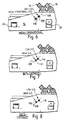
- the position 106 is that of the centre of gravity of the basket 10 when no fluids and cuttings are being carried by the screens of the machine. This position lies on a line 108 which, if extrapolated, will pass through the Centre of Action of the weights.
- the Centre of Action lies on a line (not shown) joining the two axes of rotation of the weights.
- m 1 33.5 Kg
- m 2 25.4 Kg
- r 1 0.046m
- r 2 0.042m
- the masses are stated at a speed in the range 1500-2000 rpm.
- the resultant elliptical path of the basket 10 has a major radius of 3.3 mm and a minor radius of 0.6 mm.
- Reference numeral 110 denotes the position of the mean operational Centre of Gravity of the basket.
- reference numerals 112 and 114 denote the positions of the Centre of Gravity when the basket is loaded, to half its maximum capacity, respectively with examples of high and low Specific Gravity fluids, whilst the positions of the Centre of Gravity when the basket is fully loaded with high and low density fluids are respectively indicated by numerals 116 and 118 in Figure 8.
Landscapes
- Chemical & Material Sciences (AREA)
- Chemical Kinetics & Catalysis (AREA)
- Combined Means For Separation Of Solids (AREA)
- Separation Of Solids By Using Liquids Or Pneumatic Power (AREA)
- Vibration Prevention Devices (AREA)
- Confectionery (AREA)
- Sorting Of Articles (AREA)
Claims (18)
- Machine de criblage vibrante dotée d'un carter rigide à l'intérieur duquel est monté de manière élastique un panier de criblage rigide dans lequel sont montés des cribles supérieur et inférieur, le crible supérieur présentant des mailles plus grossières que le crible inférieur, et de moyens d'entraínement pour faire vibrer le panier par rapport au carter comprenant une paire de masses contra-rotatives montées rotatives autour de deux axes parallèles espacés entre les côtés du panier, caractérisée en ce que :(1) l'espace entre les deux axes parallèles espacés et/ou leur positionnement précis par rapport au centre de gravité opérationnel moyen du panier est/sont sélectionné(s) de telle sorte que la force résultante soit du type souhaité et forme un angle souhaité par rapport aux cribles ;(2) les axes des masses contra-rotatives occupent tous deux un plan essentiellement parallèle au plan du crible supérieur et espacé juste au-dessus d'eux, pour maintenir le centre de gravité bas ;(3) le crible inférieur forme une rampe continue inclinée uniformément vers le haut depuis l'extrémité d'entrée jusqu'à l'extrémité d'évacuation et forme un angle aigu avec le crible supérieur; et(4) le moment de rotation produit par l'un des poids contra-rotatifs est différent de celui produit par l'autre, afin de produire ainsi un mouvement elliptique du panier par rapport au carter.
- Machine de criblage vibrante selon la revendication 1, dans laquelle chaque masse comprend une paire de poids similaires montés sur des côtés opposés de l'unité d'entraínement prévue pour celle-ci, et l'entraínement et les poids sont situés sur un pont traversant le panier.
- Machine de criblage vibrante selon la revendication 2, dans laquelle le pont est situé au-delà du point milieu mesuré sur la longueur du panier, plus près de son extrémité d'évacuation que de son extrémité d'entrée.
- Machine de criblage vibrante selon l'une quelconque des revendications 1 à 3, caractérisée en ce que la position de l'ensemble de poids dans les entraínements par rapport au panier est telle que l'angle du grand axe du mouvement elliptique produit par les masses contra-rotatives tend à passer par le centre de gravité du panier et à sous-tendre un angle aigu dans un sens ascendant par rapport au crible inférieur incliné.
- Machine de criblage vibrante selon l'une quelconque des revendications 1 à 4, dans laquelle, en service, le crible supérieur de maille plus grossière est essentiellement horizontal.
- Machine de criblage vibrante selon l'une quelconque des revendications 1 à 5, dans laquelle l'angle aigu entre le plan du crible inférieur et celui du crible supérieur est compris entre 2° et 30°.
- Machine de criblage vibrante selon l'une quelconque des revendications précédentes, dans laquelle le crible inférieur est adapté pour être autonettoyant de manière à réduire le risque de coinçage permanent de fines entre les interstices de la maille plus petite du crible inférieur.
- Machine de criblage vibrante selon la revendication 7, dans laquelle le crible inférieur comprend deux toiles de criblage, l'une superposée à l'autre par-dessus un cadre rigide, préalablement tendues durant la fabrication de façon à ce que la tension dans la toile inférieure soit supérieure à la tension dans la toile supérieure.
- Machine de criblage vibrante selon la revendication 8, dans laquelle les toiles sont formées de fil tissé présentant différentes tailles de maille, et les toiles en fil tissé sont liées de manière adhésive, au moins sur leur périphérie, à des cadres rigides grâce auxquels le crible est monté à l'intérieur du panier à secousses.
- Machine de criblage vibrante selon l'une quelconque des revendications précédentes, dans laquelle les cribles supérieur et inférieur peuvent tous deux être retirés du panier.
- Machine de criblage vibrante selon l'une quelconque des revendications précédentes, dans laquelle les cribles peuvent être retirés par l'extrémité du panier par laquelle les solides et les fines sont évacués en service.
- Machine de criblage vibrante selon l'une quelconque des revendications précédentes, dans laquelle le panier est monté sur quatre ressorts hélicoïdaux supportant le poids du panier et adaptés pour vibrer essentiellement librement avec de faibles amplitudes allant jusqu'à quelques millimètres par rapport au carter rigide.
- Machine de criblage vibrante selon l'une quelconque des revendications 1 à 12, dans laquelle des côtés opposés du carter rigide sont parallèles et à la verticale lorsque la machine est montée pour être utilisée et rien ne dépasse latéralement du carter rigide.
- Machine de criblage vibrante selon l'une quelconque des revendications précédentes, dans laquelle chacun desdits moyens d'entraínement comprend un moteur monté au centre d'un pont, un arbre de sortie se prolongeant axialement dans les deux direction depuis celui-ci, et des poids sont montés de façon excentrique sur les deux arbres de sortie sur des côtés opposés de chaque moteur.
- Machine de criblage vibrante selon la revendication 14, dans laquelle des paliers sont prévus pour supporter les arbres de sortie entre les moteurs et les masses à rotation excentrique, et d'autres paliers sont prévus vers l'extérieur des masses montées de façon excentrique.
- Machine de criblage vibrante selon l'une quelconque des revendications précédentes, dans laquelle des accouplements souples sont prévus entre les entraínements et les masses excentriques contra-rotatives de sorte que les forces générées par les masses rotatives montées de façon excentrique ne soient pas transmises aux paliers des moteurs.
- Machine de criblage vibrante comprenant un panier doté d'un crible incliné, des moyens d'entraínement pour faire vibrer le panier afin de provoquer la migration de matières solides déposées sur le crible le long de celui-ci, vers le haut de l'inclinaison et jusqu'à l'extrémité d'évacuation supérieure du crible de laquelle les matières solides sont évacuées, dans lequel les moyens d'entraínement exercent sur le panier une force résultante le long d'une droite passant par le centre de gravité du panier, ou à proximité de celui-ci, lorsque ce dernier est déchargé, et dans lequel l'inclinaison du crible est telle que le centre de gravité du panier continue de se trouver sur ladite droite, ou à proximité de celle-ci, pour différentes charges du panier.
- Machine de criblage vibrante selon la revendication 17, dans laquelle les moyens d'entraínement comprennent deux paires de poids et deux entraínements, chaque entraínement étant situé au centre entre ses paires de masses associées, chaque paire de masses étant montée à rotation excentrique autour de son axe d'entraínement associé, les masses étant entraínées en contra-rotation par leurs moyens d'entraínement respectifs, et dans laquelle ladite droite le long de laquelle la force résultante agit joint le centre de gravité du panier, dans des conditions de charge normales, au centre d'action des deux paires de masses.
Applications Claiming Priority (5)
| Application Number | Priority Date | Filing Date | Title |
|---|---|---|---|
| GB9621463 | 1996-10-15 | ||
| GBGB9621463.0A GB9621463D0 (en) | 1996-10-15 | 1996-10-15 | Improved vibratory screening machine |
| GBGB9623017.2A GB9623017D0 (en) | 1996-10-15 | 1996-11-05 | Improved vibratory screening machine |
| GB9623017 | 1996-11-05 | ||
| PCT/GB1997/002839 WO1998016328A1 (fr) | 1996-10-15 | 1997-10-15 | Machine de criblage a vibrations amelioree |
Publications (2)
| Publication Number | Publication Date |
|---|---|
| EP0932454A1 EP0932454A1 (fr) | 1999-08-04 |
| EP0932454B1 true EP0932454B1 (fr) | 2001-12-12 |
Family
ID=26310229
Family Applications (1)
| Application Number | Title | Priority Date | Filing Date |
|---|---|---|---|
| EP97909424A Expired - Lifetime EP0932454B1 (fr) | 1996-10-15 | 1997-10-15 | Machine de criblage a vibrations amelioree |
Country Status (6)
| Country | Link |
|---|---|
| EP (1) | EP0932454B1 (fr) |
| AU (1) | AU711860B2 (fr) |
| DE (1) | DE69709146T2 (fr) |
| DK (1) | DK0932454T3 (fr) |
| NO (1) | NO319322B1 (fr) |
| WO (1) | WO1998016328A1 (fr) |
Families Citing this family (29)
| Publication number | Priority date | Publication date | Assignee | Title |
|---|---|---|---|---|
| GB0121353D0 (en) | 2001-09-04 | 2001-10-24 | Rig Technology Ltd | Improvements in or relating to transport of waste materials |
| US20050242003A1 (en) | 2004-04-29 | 2005-11-03 | Eric Scott | Automatic vibratory separator |
| GB0301509D0 (en) | 2002-10-17 | 2003-02-19 | Varco Int | Vibratory seperator and screen assembly |
| US6868972B2 (en) * | 2002-11-04 | 2005-03-22 | Varco I/P, Inc. | Fluid flow diffusers and vibratory separators |
| US20060113220A1 (en) | 2002-11-06 | 2006-06-01 | Eric Scott | Upflow or downflow separator or shaker with piezoelectric or electromagnetic vibrator |
| US7571817B2 (en) | 2002-11-06 | 2009-08-11 | Varco I/P, Inc. | Automatic separator or shaker with electromagnetic vibrator apparatus |
| CA2505628C (fr) | 2003-03-19 | 2007-12-18 | Varco I/P, Inc. | Appareil et procede pour deplacer des deblais de forage |
| WO2004110589A1 (fr) | 2003-06-12 | 2004-12-23 | Axiom Process Limited | Appareil de criblage |
| US8453844B2 (en) | 2003-06-12 | 2013-06-04 | Axiom Process Ltd. | Screening system |
| CA2551620C (fr) | 2004-01-22 | 2010-05-11 | Varco I/P, Inc. | Appareil de tamisage et procede de montage d'un ensemble de tamisage dans un separateur vibratoire |
| PE20070556A1 (es) * | 2005-08-04 | 2007-06-14 | Metso Brasil Ind E Com Ltda | Sistema de control de eficiencia de separacion en tamices vibratorios |
| GB0603246D0 (en) | 2006-02-17 | 2006-03-29 | Genesis Fluid Solutions Llc | Duct for use in an apparatus for separating suspended solid from water and a method feeding water having suspended solid |
| US8556083B2 (en) | 2008-10-10 | 2013-10-15 | National Oilwell Varco L.P. | Shale shakers with selective series/parallel flow path conversion |
| US9079222B2 (en) | 2008-10-10 | 2015-07-14 | National Oilwell Varco, L.P. | Shale shaker |
| DK2544830T3 (en) | 2010-03-08 | 2017-10-16 | Nat Oilwell Varco Lp | Apparatus and method for separating solids from a drilling fluid containing solids |
| GB2479919B (en) | 2010-04-29 | 2012-10-03 | Nat Oilwell Varco Lp | Apparatus and method for separating solids from a solids laden drilling fluid |
| GB2490647B (en) | 2011-01-27 | 2013-05-22 | Nat Oilwell Varco Lp | Screen assembly and a method for making same |
| GB2523488B (en) | 2011-07-15 | 2016-02-10 | Nat Oilwell Varco Lp | Apparatus and method for separating solids from a solids laden drilling mud |
| GB2505483B (en) * | 2012-08-31 | 2014-11-26 | Cde Global Ltd | Vibrating screen |
| US9643111B2 (en) | 2013-03-08 | 2017-05-09 | National Oilwell Varco, L.P. | Vector maximizing screen |
| GB2514589B (en) | 2013-05-30 | 2020-01-29 | Nat Oilwell Varco Lp | Centrifuge for separating solids from solids laden drilling fluid |
| FR3007296A1 (fr) * | 2013-06-21 | 2014-12-26 | Saur | Procede et installation de sechage de boues |
| DE102017116312B4 (de) * | 2017-07-19 | 2023-07-06 | HÜBNER GmbH & Co. KG | Textilverstärkter Formschlauch in Form eines Dichtungsschlauchs zur Abdichtung eines Siebs gegenüber einem Maschinenrahmen einer Vibrationssiebvorrichtung, sowie eine derartige Vibrationssiebvorrichtung, und textilverstärkter Formschlauch in Form eines Dichtungsschlauchs zur Abdichtung eines Türspaltes einer Türöffnung eines Fahrzeugs des öffentlichen Personentransportverkehrs, sowie ein derartiges Fahrzeug und Verfahren zur Herstellung des Formschlauchs |
| BR102017026766B1 (pt) | 2017-12-12 | 2022-10-25 | Metso Brasil Industria E Comércio Ltda | Vibrador mecânico de caixa, para peneiras vibratórias |
| CN110318698B (zh) * | 2019-06-11 | 2025-04-04 | 濮阳市中原锐实达石油设备有限公司 | 一种自控倾角振动频率智能化振动筛 |
| CN112973236B (zh) * | 2021-04-16 | 2024-05-17 | 珠海城市职业技术学院 | 一种可调节过滤速度的机械自动化药材加工滤材设备 |
| CN114653588B (zh) * | 2022-03-16 | 2025-12-19 | 红云红河烟草(集团)有限责任公司 | 一种制丝线双层振动筛分机传动机构 |
| CN117380011B (zh) * | 2023-10-20 | 2024-04-30 | 云南凯瑞特工程机械设备有限公司 | 一种机制砂生产系统 |
| CN117380540B (zh) * | 2023-12-12 | 2024-03-22 | 山东寿光第一建筑有限公司 | 一种土木工程用细沙筛分装置 |
Family Cites Families (11)
| Publication number | Priority date | Publication date | Assignee | Title |
|---|---|---|---|---|
| FR59077E (fr) * | 1948-11-23 | 1954-04-22 | Tamis à excitatrice orientable | |
| US3796299A (en) * | 1971-07-08 | 1974-03-12 | Gen Kinematics Corp | Vibratory material handling device with variable force application |
| SE407163B (sv) * | 1977-07-13 | 1979-03-19 | Morgaardshammar Ab | Drivdon for astadkommande av en elliptiskt skakrorelse hos en fjedrande upphengd anordning |
| SE445090B (sv) * | 1978-09-12 | 1986-06-02 | Morgaardshammar Ab | Sett att reglera kastvinkeln vid en vibrerande anordning |
| US4340469A (en) * | 1981-01-23 | 1982-07-20 | Spokane Crusher Mfg. Co. | Vibratory screen apparatus |
| GB2123520B (en) * | 1982-07-08 | 1985-10-02 | Viking Dynamics Limited | Vibrating screen |
| US4826017A (en) * | 1985-05-03 | 1989-05-02 | Velmet (Proprietary) Limited | Vibrating screen |
| GB2206502B (en) * | 1987-07-07 | 1991-08-21 | Thule United Ltd | Filtering screens |
| US4882054A (en) * | 1988-08-22 | 1989-11-21 | Derrick Manufacturing Corporation | Vibratory screening machine with tiltable screen frame and adjustable discharge weir |
| GB2266475B (en) * | 1992-04-21 | 1995-08-16 | Alfa Laval Separation Ab | Mounting and tensioning arrangements for screens |
| AU707680B2 (en) * | 1994-09-13 | 1999-07-15 | Varco I/P Inc. | Improvements in and relating to vibratory screening apparatus |
-
1997
- 1997-10-15 EP EP97909424A patent/EP0932454B1/fr not_active Expired - Lifetime
- 1997-10-15 DK DK97909424T patent/DK0932454T3/da active
- 1997-10-15 AU AU47112/97A patent/AU711860B2/en not_active Expired
- 1997-10-15 DE DE69709146T patent/DE69709146T2/de not_active Expired - Lifetime
- 1997-10-15 WO PCT/GB1997/002839 patent/WO1998016328A1/fr not_active Ceased
-
1999
- 1999-04-09 NO NO19991699A patent/NO319322B1/no not_active IP Right Cessation
Also Published As
| Publication number | Publication date |
|---|---|
| NO319322B1 (no) | 2005-07-11 |
| WO1998016328A1 (fr) | 1998-04-23 |
| DE69709146T2 (de) | 2002-07-04 |
| DK0932454T3 (da) | 2002-02-25 |
| NO991699D0 (no) | 1999-04-09 |
| AU4711297A (en) | 1998-05-11 |
| EP0932454A1 (fr) | 1999-08-04 |
| DE69709146D1 (de) | 2002-01-24 |
| NO991699L (no) | 1999-04-09 |
| AU711860B2 (en) | 1999-10-21 |
Similar Documents
| Publication | Publication Date | Title |
|---|---|---|
| US6155428A (en) | Vibratory screening machine | |
| EP0932454B1 (fr) | Machine de criblage a vibrations amelioree | |
| GB2318401A (en) | Vibratory screening machine | |
| US8807343B2 (en) | Screening method and apparatus | |
| US8869986B2 (en) | Screening methods and apparatus | |
| US9475095B2 (en) | Shaker with automatic motion | |
| CA2711780C (fr) | Appareil et procede pour la separation de solides d'un fluide charge de solides | |
| EP2910313B1 (fr) | Ensemble d'écran | |
| US5685982A (en) | Vectored thrust shale shaker | |
| EP2890505B1 (fr) | Tamis vibrant | |
| AU2018382236B2 (en) | A vibrating screen | |
| WO2009013511A2 (fr) | Dispositif de tamisage vibrant | |
| GB1575312A (en) | Vibratory sifting machines | |
| CA2628757A1 (fr) | Appareil et procede pour separer des elements solides d'un fluide charge en elements solides | |
| EP0932438A1 (fr) | Tamis vibrant ameliore | |
| EP4074399B1 (fr) | Écran de déshydratation | |
| JP2684535B2 (ja) | 原石回収プラント | |
| SU975117A1 (ru) | Способ грохочени | |
| RU2074774C1 (ru) | Способ разделения сыпучих материалов на ситах |
Legal Events
| Date | Code | Title | Description |
|---|---|---|---|
| PUAI | Public reference made under article 153(3) epc to a published international application that has entered the european phase |
Free format text: ORIGINAL CODE: 0009012 |
|
| 17P | Request for examination filed |
Effective date: 19990201 |
|
| AK | Designated contracting states |
Kind code of ref document: A1 Designated state(s): DE DK FR IT NL |
|
| GRAG | Despatch of communication of intention to grant |
Free format text: ORIGINAL CODE: EPIDOS AGRA |
|
| 17Q | First examination report despatched |
Effective date: 20010222 |
|
| GRAG | Despatch of communication of intention to grant |
Free format text: ORIGINAL CODE: EPIDOS AGRA |
|
| GRAH | Despatch of communication of intention to grant a patent |
Free format text: ORIGINAL CODE: EPIDOS IGRA |
|
| GRAH | Despatch of communication of intention to grant a patent |
Free format text: ORIGINAL CODE: EPIDOS IGRA |
|
| GRAA | (expected) grant |
Free format text: ORIGINAL CODE: 0009210 |
|
| AK | Designated contracting states |
Kind code of ref document: B1 Designated state(s): DE DK FR IT NL |
|
| REF | Corresponds to: |
Ref document number: 69709146 Country of ref document: DE Date of ref document: 20020124 |
|
| REG | Reference to a national code |
Ref country code: DK Ref legal event code: T3 |
|
| ET | Fr: translation filed | ||
| PLBE | No opposition filed within time limit |
Free format text: ORIGINAL CODE: 0009261 |
|
| STAA | Information on the status of an ep patent application or granted ep patent |
Free format text: STATUS: NO OPPOSITION FILED WITHIN TIME LIMIT |
|
| 26N | No opposition filed | ||
| NLS | Nl: assignments of ep-patents |
Owner name: VARCO I/P INC. |
|
| REG | Reference to a national code |
Ref country code: FR Ref legal event code: TP |
|
| REG | Reference to a national code |
Ref country code: FR Ref legal event code: PLFP Year of fee payment: 19 |
|
| REG | Reference to a national code |
Ref country code: FR Ref legal event code: PLFP Year of fee payment: 20 |
|
| PGFP | Annual fee paid to national office [announced via postgrant information from national office to epo] |
Ref country code: FR Payment date: 20160919 Year of fee payment: 20 |
|
| PGFP | Annual fee paid to national office [announced via postgrant information from national office to epo] |
Ref country code: DE Payment date: 20161011 Year of fee payment: 20 Ref country code: DK Payment date: 20161012 Year of fee payment: 20 Ref country code: NL Payment date: 20161010 Year of fee payment: 20 |
|
| PGFP | Annual fee paid to national office [announced via postgrant information from national office to epo] |
Ref country code: IT Payment date: 20161024 Year of fee payment: 20 |
|
| REG | Reference to a national code |
Ref country code: DE Ref legal event code: R071 Ref document number: 69709146 Country of ref document: DE |
|
| REG | Reference to a national code |
Ref country code: DK Ref legal event code: EUP Effective date: 20171015 |
|
| REG | Reference to a national code |
Ref country code: NL Ref legal event code: MK Effective date: 20171014 |