EP0932515B2 - Dispositif de filtre destine au filtrage d'un fluide - Google Patents
Dispositif de filtre destine au filtrage d'un fluide Download PDFInfo
- Publication number
- EP0932515B2 EP0932515B2 EP97912805A EP97912805A EP0932515B2 EP 0932515 B2 EP0932515 B2 EP 0932515B2 EP 97912805 A EP97912805 A EP 97912805A EP 97912805 A EP97912805 A EP 97912805A EP 0932515 B2 EP0932515 B2 EP 0932515B2
- Authority
- EP
- European Patent Office
- Prior art keywords
- filter element
- filter
- sealing lip
- thickness
- element frame
- Prior art date
- Legal status (The legal status is an assumption and is not a legal conclusion. Google has not performed a legal analysis and makes no representation as to the accuracy of the status listed.)
- Expired - Lifetime
Links
- 239000012530 fluid Substances 0.000 title claims abstract description 13
- 238000001914 filtration Methods 0.000 title claims abstract description 8
- 238000007789 sealing Methods 0.000 claims abstract description 93
- 239000000463 material Substances 0.000 claims abstract description 59
- 238000005452 bending Methods 0.000 claims abstract description 44
- 230000007423 decrease Effects 0.000 claims description 5
- 238000002347 injection Methods 0.000 description 12
- 239000007924 injection Substances 0.000 description 12
- 239000004033 plastic Substances 0.000 description 12
- 229920003023 plastic Polymers 0.000 description 12
- -1 e.g. Substances 0.000 description 11
- 238000004519 manufacturing process Methods 0.000 description 10
- 239000004743 Polypropylene Substances 0.000 description 8
- 229920001155 polypropylene Polymers 0.000 description 8
- 238000000034 method Methods 0.000 description 3
- 229920000098 polyolefin Polymers 0.000 description 3
- 239000004698 Polyethylene Substances 0.000 description 2
- 230000000694 effects Effects 0.000 description 2
- 229920000573 polyethylene Polymers 0.000 description 2
- 239000002861 polymer material Substances 0.000 description 2
- 210000002105 tongue Anatomy 0.000 description 2
- 229920001410 Microfiber Polymers 0.000 description 1
- 229920000297 Rayon Polymers 0.000 description 1
- 230000001154 acute effect Effects 0.000 description 1
- 238000007664 blowing Methods 0.000 description 1
- 239000013013 elastic material Substances 0.000 description 1
- 239000000835 fiber Substances 0.000 description 1
- 238000001746 injection moulding Methods 0.000 description 1
- 239000003658 microfiber Substances 0.000 description 1
- 239000002991 molded plastic Substances 0.000 description 1
- 238000000465 moulding Methods 0.000 description 1
- 239000004745 nonwoven fabric Substances 0.000 description 1
- 239000000123 paper Substances 0.000 description 1
- 230000007704 transition Effects 0.000 description 1
- 238000009423 ventilation Methods 0.000 description 1
Images

Classifications
-
- B—PERFORMING OPERATIONS; TRANSPORTING
- B60—VEHICLES IN GENERAL
- B60H—ARRANGEMENTS OF HEATING, COOLING, VENTILATING OR OTHER AIR-TREATING DEVICES SPECIALLY ADAPTED FOR PASSENGER OR GOODS SPACES OF VEHICLES
- B60H3/00—Other air-treating devices
- B60H3/06—Filtering
-
- B—PERFORMING OPERATIONS; TRANSPORTING
- B01—PHYSICAL OR CHEMICAL PROCESSES OR APPARATUS IN GENERAL
- B01D—SEPARATION
- B01D46/00—Filters or filtering processes specially modified for separating dispersed particles from gases or vapours
- B01D46/52—Particle separators, e.g. dust precipitators, using filters embodying folded corrugated or wound sheet material
- B01D46/521—Particle separators, e.g. dust precipitators, using filters embodying folded corrugated or wound sheet material using folded, pleated material
- B01D46/523—Particle separators, e.g. dust precipitators, using filters embodying folded corrugated or wound sheet material using folded, pleated material with means for maintaining spacing between the pleats or folds
-
- B—PERFORMING OPERATIONS; TRANSPORTING
- B01—PHYSICAL OR CHEMICAL PROCESSES OR APPARATUS IN GENERAL
- B01D—SEPARATION
- B01D46/00—Filters or filtering processes specially modified for separating dispersed particles from gases or vapours
- B01D46/10—Particle separators, e.g. dust precipitators, using filter plates, sheets or pads having plane surfaces
-
- B—PERFORMING OPERATIONS; TRANSPORTING
- B60—VEHICLES IN GENERAL
- B60H—ARRANGEMENTS OF HEATING, COOLING, VENTILATING OR OTHER AIR-TREATING DEVICES SPECIALLY ADAPTED FOR PASSENGER OR GOODS SPACES OF VEHICLES
- B60H3/00—Other air-treating devices
- B60H3/06—Filtering
- B60H3/0658—Filter elements specially adapted for their arrangement in vehicles
-
- B—PERFORMING OPERATIONS; TRANSPORTING
- B01—PHYSICAL OR CHEMICAL PROCESSES OR APPARATUS IN GENERAL
- B01D—SEPARATION
- B01D2271/00—Sealings for filters specially adapted for separating dispersed particles from gases or vapours
- B01D2271/02—Gaskets, sealings
- B01D2271/027—Radial sealings
-
- Y—GENERAL TAGGING OF NEW TECHNOLOGICAL DEVELOPMENTS; GENERAL TAGGING OF CROSS-SECTIONAL TECHNOLOGIES SPANNING OVER SEVERAL SECTIONS OF THE IPC; TECHNICAL SUBJECTS COVERED BY FORMER USPC CROSS-REFERENCE ART COLLECTIONS [XRACs] AND DIGESTS
- Y10—TECHNICAL SUBJECTS COVERED BY FORMER USPC
- Y10S—TECHNICAL SUBJECTS COVERED BY FORMER USPC CROSS-REFERENCE ART COLLECTIONS [XRACs] AND DIGESTS
- Y10S55/00—Gas separation
- Y10S55/28—Carburetor attached
-
- Y—GENERAL TAGGING OF NEW TECHNOLOGICAL DEVELOPMENTS; GENERAL TAGGING OF CROSS-SECTIONAL TECHNOLOGIES SPANNING OVER SEVERAL SECTIONS OF THE IPC; TECHNICAL SUBJECTS COVERED BY FORMER USPC CROSS-REFERENCE ART COLLECTIONS [XRACs] AND DIGESTS
- Y10—TECHNICAL SUBJECTS COVERED BY FORMER USPC
- Y10S—TECHNICAL SUBJECTS COVERED BY FORMER USPC CROSS-REFERENCE ART COLLECTIONS [XRACs] AND DIGESTS
- Y10S55/00—Gas separation
- Y10S55/30—Exhaust treatment
Definitions
- the invention refers to a filter device for filtering a fluid, this fluid being, in particular, the air flowing into the passenger compartment of a vehicle.
- the filter device includes a filter element provided with a filter material limited by a border with which a filter element frame is connected.
- the filter element frame extends at least partly along the border of the filter material.
- the filter material in particular a filter paper or a non-woven filter material
- the filter element frame is disposed extending around the periphery of the filter material; however, with a filter material pleated in zigzag shape it sometimes suffices to make the filter frame extend only along the pleated lateral edges of the filter material.
- such filter elements are inserted into the fluid inlet opening of a device through which filtered fluid will flow subsequently.
- a sealing profile is applied in this area, the profile being a strip generally made of an elastic material, e.g., rubber or foamed material.
- a filter element that has a pleated filter material surrounded by a peripherally extending filter element frame of cardboard material.
- This filter element frame comprises protruding tongues bent towards the outer side of the filter element frame facing away from the filter material.
- These cardboard tongues projecting under an acute angle serve as sealing lips resiliently abutting, from inside, the edge of an inlet opening receiving the filter element.
- a filter elemen according to the preamble of claim 1 wherein the filter element frame surrounding the filter material is made of a plastics material and has a sealing lip integrally formed thereto which comprises a bending section adjoining the filter element frame and an end portion adjoining the bending section.
- European Patent 0 380 026 describes a filter element, wherein a flat filter in the shape of a filter material web is inserted laterally into slots provided in a housing receiving the filter element.
- the sealing between the filter element and the receiving housing is achieved in particular by the labyrinth-like design of the area between the edges of the filter element and the slots in the receiving housing, which causes a multiple deflection of the fluid flow, thereby resulting in a sealing effect.
- the filter element For reasons of cost, manufacturers are intent on providing the filter element as a plastics material part. Most of the plastics materials used today that can be produced and processed at low cost, however, have a comparatively great thermal expansion factor and manufacture-related deviations in measures, which is why in particular largesized filter elements must be insertable into the receiving housings with a corresponding play. In order to achieve a sufficient sealing between the filter frame and the receiving housing under the temperature conditions to be expected, the sealing striphas to be formed accordingly. For reasons of manufacturing techniques, the filter elements should be provided with integral sealing lips projecting from their filter element frame, whereby the sealing lips should also have a relatively great thickness in order to always abut the receiving housing.
- sealing lips To maintain the elasticity of the sealing lips when the filter element is inserted into the receiving housing, they must not be bent beyond their yielding point in the bending section. With sealing lips of plastics material this means that the sealing lips have to be relatively thin. Yet, this is disadvantageous in the manufacturing process, since the injection mold cavities used in making the plastics filter element frame create a comparatively strong (flow) resistance in the area of the thin sealing lip. This requires increased material pressures and causes greater loads on the injection mold and the molded part, in particular when viscose materials such as polypropylene are used, which has proved advantageous as a material for filter devices of the kind referred to.
- the invention provides a filter device provided with a filter element comprising a filter element frame and a filter material with a border, the filter element frame being connected with the filter material and extending at least partly along the border of the filter material.
- the filter element frame is provided with a projecting resilient sealing lip for abutting a device receiving the filter element, the sealing lip having at least one bending section of a first thickness facing the filter element frame and at least one enlarged section adjoining the at least one bending section and facing away from the filter element, at least a part of the enlarged section being of a second thickness greater film the first thickness in the at least one bending section.
- the sealing lip of the filter element of the present filter device has at least one bending section and at least one enlarged section.
- the bending section faces the filter element frame, while the enlarged position adjoining the bending section is averted from the filter element.
- the enlarged section has at least a part where the thickness is greater than that of the bending section.
- the sealing lip may have one or a plurality of such pairs of sections, each comprising a bending section and an adjoining enlarged section. Should the sealing lip have a plurality of such pairs of portions, the bending sections and the enlarged sections are arranged in alternating succession.
- the sealing lip is elastically deformable in its bending section(s) when, upon inserting the filter element into a receiving housing or another device of the kind, the sealing lip comes into abutment with the same.
- the bending section should be of an appropriate length or be provided with a corresponding number of shorter bending sections and intermediate enlarged sections.
- the present invention remedies the problem by making only a part of the extension of the sealing lip sufficiently thin for a resilient bending of the sealing lip.
- the sealing lip has a greater thickness; these parts correspond to the enlarged section(s).
- the cavity provided for forming the sealing lip has one or more thin constrictions only in parts thereof, the constrictions forming the bending section(s).
- the cavity is larger, which is why the plastics material can be readily filled without having to use an excessively high injection pressure so that no increased load on the injection mold and the molded part is expected.
- the invention provides for a filter device, the filter element of which may be provided with a relatively long sealing lip that is resiliently deformable at least in parts thereof and may be produced by injection molding together with the filter element frame as an integral part thereof.
- plastic materials of relatively high viscosity may be employed, such as polypropylene.
- each enlarged section has an adjoining portion and an end portion.
- the adjoining portion faces the filter element frame and is adjacent to the bending section. Accordingly, the end portion extends away from the filter element frame up to the free end of the enlarged section or to the next bending section, if several pairs of bending and enlarged portions are provided.
- the thickness of the enlarged section increases, in particular linearly, whereas the thickness of the sealing lip decreases in the end portion of the enlarged section.
- the end portion and the adjoining portion adjoin each other.
- an intermediate portion is disposed between these two portions, in which the thickness of the sealing lip is constant.
- the end portion of an enlarged section of the sealing lip extends over a greater length than the adjoining portion.
- the length of the end portion is two to four times the length of the adjoining portion.
- the sealing lip In the direction of its thickness, the sealing lip is defined by an upper and a lower surface.
- the lower surface is smooth, while the upper surface has a profile whereby the different sections or the different portions of the sections are formed.
- the end of the sealing lip facing away from the filter element frame is tapered in its thickness.
- this end is part of the end portion of the enlarged section farthest away from the filter element frame.
- the same plastics material may be used for the sealing lip and the filter element frame.
- this material is a polypropylene, polyethylene or another polyolefin material.
- the filter material consists of the same material as the filter frame and the sealing lip.
- the filter material is a non-woven fabric of microfibers that are adhered, welded or (mechanically) engaged among each other, the non-woven being connected with a reticular support structure also of polyolefin material.
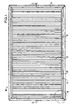
- Fig. 1 is a plan view of the filter element 10 according to a first embodiment of the invention.
- this filter element 10 serves to filter the air streaming into the passenger cabin of a motor vehicle.
- This air stream is maintained by a device provided to this purpose, e.g. a blower or the like adapted for blowing or sucking air through the filter element.
- a device provided to this purpose, e.g. a blower or the like adapted for blowing or sucking air through the filter element.
- the term "means” has a rather general meaning in the context of this invention; it is meant to comprise all devices and circumstances providing for a (fluid) flow passing through the filter element.
- the filter element 10 has a pleated filter material 12 with a rectangularly extending border 14. As illustrated in particular in Fig. 2 , the filter material is comprised of a plastics supporting scrim 16 with a non-woven filter material 18 applied thereon.
- a rectangular filter element frame 20 formed as a strip extends around the filter material 12. On the outer side 22 of the frame facing away from the filter material 12, the filter element frame 20 is provided with a circumferentially extending sealing lip 24.
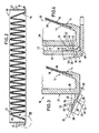
- sealing lip 24 As well as its function for sealing the filter element 10 when, for example, the same is inserted into the air inlet opening of a unit to be supplied with filtered air, e.g. the air inlet duct of the passenger compartment in a vehicle, will be described below in connection with Figs. 3 and 4 .
- the filter element 10 is made as an injection molded part and consists of a polymer material, in particular of polypropylene, polyethylene or other polyolefins.
- the production of the filter element 10 is carried out in an insert molding process.
- the filter material 12 is held clamped in the injection mold, being left free in the border zone.
- This free border 14 protrudes into that cavity of the mold that forms the filter element frame 20.
- Connected to this mold cavity is the mold cavity forming the sealing lip 24.
- the free border 14 of the filter material 12 is molded around, thereby obtaining the connection between the filter element frame 20 and the filter material 12.
- the injection mold is preheated to a temperature far below the temperature of the injected polymer material so that the injection mold also serves to cool the injected material faster.
- the filter element consists, in particular, of polypropylene.
- This material is of general usefulness in this respect, due to its being comparatively easy to work into molded parts.
- the temperatures to be expected in a vehicle and to which the individual components of the ventilation system are subjected are well below the softening temperature range of polypropylene.
- polypropylene is a comparatively low-cost material. Further, it is recyclable.
- the sealing lip 24 has different sections 26, 28 starting from the filter element frame 20.
- the section 26 immediately adjoining the filter element frame 20 is a bending section where the sealing lip 24 has a reduced thickness 30.
- This thickness 30 is selected such that the sealing lip 24 may be deformed elastically in its bending section. 26.
- the lower limit of the thickness 30 is defined by the fact that the sealing lip 24 should be sufficiently resilient in its bending section 26 after deformation so that it abuts a filter element housing or a similar device with sufficient abutment force (see Fig. 4 ).
- the upper limit of the thickness 30 is determined by the fact that the sealing lip 24 should de deformable in the bending section 26 such that the filter element IO can be inserted into the filter element housing.
- the thickness 30 of the bending section 26 should substantially have a value between 0.20 mm and 0.40 mm and, preferably, between 0.25 rmn and 0.30 mm.
- the section 28 Joining the bending section 26 is the section 28 which is an enlarged section where the thickness 32 of the sealing lip 20 is greater than the thickness 30 in the bending section 26.
- the thickness 32 is about twice to five times, and in particular about three times, the thickness 30.
- the enlarged section 28 itself is divided into an adjoining portion 34 and an end portion 36 adjoining the adjoining portion 34.
- the thickness of the enlarged section 28 increases, preferably linearly, from the value of the thickness 30 of the bending section 26 to the value of the thickness 32, the transitions being rounded.
- the adjoining portion 34 is followed by the end portion 36, in the course of which the thickness of the enlarged section 28 decreases from the value of the thickness 32 to zero.
- the sealing lip 24 tapers towards the free end 38 of the sealing lip 24 to about the thickness that it has in the bending section 26.
- a vertex or, more precisely, a "vertex line" 40 is obtained in the enlarged section 28, from which vertex the thickness of the enlarged section 28 decreases substantially linearly towards both sides of the vertex line 40.
- the enlarged section 28 is about one to five times the length, and preferably three times, the length of the bending section 26.
- the end portion 36 is about one to five times, and preferably four times, the length of the adjoining portion 34.
- the sealing lip 24 bends particularly in the area of the bending section 26 when the filter element 10 is inserted into the inlet opening 42 of a receiving housing indicated at 44.
- the sealing lip 24 extends substantially straight, there also is some deformation of the sealing lip 24 in the part 46 of the end portion 36 that is adjacent the free end 38.
- the planar outwardfacing lower surface 48 of the sealing lip 24 abuts the surface 50 defining the inlet opening 42 of the receiving housing 44.
- the lower surface 48 of the sealing lip 24 faces away from the filter element frame 20
- the inward-facing upper surface 52 of the sealing lip 24 faces towards the filter element frame 20.
- the upper surface 52 has a triangular raised part 54 that determines the enlarged section 28.
- the sealing lip 24 is slit in the corner area 56.
- the comer areas 56 of the sealing lip 24 are provided with a slit 58 at an angle of 45° and extending from the free end 38 of the sealing lip 24 up to the filter element frame 20, allowing the sealing lips 24, which extend at right angles with respect to each other, to be deformed freely also in the corner areas 56 and avoiding stuffing in these comer areas 56 when the filter element 10 is inserted into the inlet opening 42 of the receiving housing 44. Accordingly, the sealing lip 24 abuts the inner surface 50 of the inlet opening 42 also in the corner areas 56. Thus, a reliable seal is obtained even in the case of an inlet opening 42 of the receiving housing 44 having inner surfaces 50 that extend at right angles with respect to each other.
- FIG. 6 An alternative design of the corner area of the sealing lip in a second embodiment of the filter element, is illustrated in Fig. 6.
- the filter element 60 of Fig. 6 comprises a filter material 62 enclosed by a rectangular filter element frame 70.
- the outer side 72 of the filter element frame 70, facing away from the filter material 62, is provided with an integral sealing lip 74.
- the structure and the design of this sealing lip 74 is similar to the sealing lip 24 of the filter element 10 shown in Figs. 1 to 5 .
- the sealing lip 74 extends in a curve 78 of 90°. In the end portion of this curve 78 of 90°, the sealing lip 74 is provided with two V-shaped slits 80 extending over the entire width of the sealing lip 72. These two slits 80 allow for the deformation of the sealing lips 74 in the corner areas 76 without stuffing.
- the curve 78 of the free end 38 of the sealing lip 74 guarantees a sealing abutment on the inner surfaces 50 of the inlet opening 42 of the receiving housing 44 when these are rounded in the corner areas.
Landscapes
- Chemical & Material Sciences (AREA)
- Chemical Kinetics & Catalysis (AREA)
- Engineering & Computer Science (AREA)
- Mechanical Engineering (AREA)
- Filtering Of Dispersed Particles In Gases (AREA)
- Fluid-Pressure Circuits (AREA)
- Electrical Discharge Machining, Electrochemical Machining, And Combined Machining (AREA)
- Filtration Of Liquid (AREA)
Claims (15)
- Dispositif de filtre pour filtrer un fluide, en particulier pour filtrer l'air circulant dans l'habitacle d'un véhicule, comprenant :- un élément filtrant (10 ; 60) comprenant un matériau filtrant (12 ; 62) ayant une bordure (14 ; 64) et- un cadre (20 ; 70) de l'élément filtrant relié au matériau filtrant (12 ; 62) et s'étendant au moins partiellement le long de la bordure (14 ; 64) du matériau filtrant, le cadre (20 ; 70) de l'élément filtrant étant doté d'une lèvre d'étanchéité (24 ; 74) élastique et saillante, pour venir en appui sur un dispositif (42, 44, 48) recevant l'élément filtrant (10 ; 60),caractérisé- en ce que la lèvre d'étanchéité (24 ; 74) ayant au moins une section de courbure (26), d'une première épaisseur (30), faisant face au cadre (20 ; 70) de l'élément filtrant, et au moins une section agrandie (28) contiguë à la section de courbure (26) au moins au nombre de un, et éloignée de l'élément filtrant (12 ; 62), au moins une partie (40) de la section élargie étant d'une seconde épaisseur (32) plus importante que la première épaisseur (30) dans la section de courbure (26) au moins au nombre de un, et dans laquelle la section agrandie (28) est de une à cinq fois égale à la longueur de la section de courbure (26).
- Dispositif de filtre selon la revendication 1, dans lequel l'épaisseur de la section agrandie de la lèvre d'étanchéité (24 ; 74) augmente dans une partie contiguë (34) de la section agrandie (28) adjacente à la section de courbure (26) et diminue dans une partie d'extrémité (36) de la section agrandie (28) éloignée de la section de courbure (26).
- Dispositif de filtre selon la revendication 2, dans lequel l'augmentation d'épaisseur dans la partie contiguë (34) et/ou la diminution d'épaisseur dans la partie d'extrémité (36) sont linéaires.
- Dispositif de filtre selon la revendication 2 ou 3, dans lequel la partie d'extrémité (36) est adjacente à la partie contiguë (34).
- Dispositif de filtre selon l'une quelconque des revendications 2 à 4, dans lequel la partie d'extrémité (36) est plus grande en dimension que la partie contiguë (34).
- Dispositif de filtre selon la revendication 5, dans lequel la dimension de la partie d'extrémité (36) est environ de deux à quatre fois égale à la dimension de la partie contiguë (34).
- Dispositif de filtre selon l'une quelconque des revendications 1 à 6, dans lequel la seconde épaisseur (32) est environ de deux à cinq fois égale à la première épaisseur (30).
- Dispositif de filtre selon la revendication 7, dans lequel la seconde épaisseur (32) est égale à environ trois fois la première épaisseur (30).
- Dispositif de filtre selon l'une quelconque des revendications 1 à 8, dans lequel la lèvre d'étanchéité (24 ; 74) a une surface inférieure plane (48) et une surface supérieure profilée (52).
- Dispositif de filtre selon l'une quelconque des revendications 1 à 9, dans lequel la lèvre d'étanchéité (24 ; 74) est formée en étant solidaire du cadre (20 ; 70) de l'élément filtrant et où la lèvre d'étanchéité (24 ; 74) est disposée sur le côté extérieur du cadre (20 ; 70) de l'élément filtrant qui est éloigné du matériau filtrant (12 ; 72).
- Dispositif de filtre selon l'une quelconque des revendications 1 à 10, dans lequel la lèvre d'étanchéité (24 ; 74) a une partie angulaire qui s'étend autour d'un angle du cadre (20 ; 70) de l'élément filtrant et qui est réduite là où la lèvre d'étanchéité (24) a une fente (58) dans ladite partie angulaire (56) qui commence au niveau de l'extrémité (38) de la lèvre d'étanchéité (24) éloignée du cadre (20) de l'élément filtrant et qui se termine à proximité du cadre (20) de l'élément filtrant.
- Dispositif de filtre selon l'une quelconque des revendications 1 à 10, dans lequel la lèvre d'étanchéité (74) a une partie angulaire (76) qui s'étend autour d'un angle du cadre (70) de l'élément filtrant et qui est arrondie là où la lèvre d'étanchéité (74) a deux fentes respectives (78) sur les deux côtés de ladite partie angulaire arrondie (76) qui commence au niveau de l'extrémité (78) de la lèvre d'étanchéité (74) éloignée du cadre (70) de l'élément filtrant et qui se termine à proximité du cadre (70) de l'élément filtrant.
- Véhicule comprenant :- un habitacle, et- un dispositif de filtre (10 ; 60) tel qu'il est défini dans l'une quelconque des revendications 1 à 12.
- Véhicule selon la revendication 13, où le véhicule est un véhicule à moteur.
- Utilisation d'un dispositif de filtre selon l'une quelconque des revendications 1 à 12, pour filtrer l'air circulant dans l'habitacle d'un véhicule.
Applications Claiming Priority (3)
| Application Number | Priority Date | Filing Date | Title |
|---|---|---|---|
| DE19644214 | 1996-10-24 | ||
| DE19644214 | 1996-10-24 | ||
| PCT/US1997/018916 WO1998017490A1 (fr) | 1996-10-24 | 1997-10-22 | Dispositif de filtre destine au filtrage d'un fluide |
Publications (3)
| Publication Number | Publication Date |
|---|---|
| EP0932515A1 EP0932515A1 (fr) | 1999-08-04 |
| EP0932515B1 EP0932515B1 (fr) | 2001-09-05 |
| EP0932515B2 true EP0932515B2 (fr) | 2008-02-20 |
Family
ID=7809870
Family Applications (1)
| Application Number | Title | Priority Date | Filing Date |
|---|---|---|---|
| EP97912805A Expired - Lifetime EP0932515B2 (fr) | 1996-10-24 | 1997-10-22 | Dispositif de filtre destine au filtrage d'un fluide |
Country Status (10)
| Country | Link |
|---|---|
| US (1) | US5902361A (fr) |
| EP (1) | EP0932515B2 (fr) |
| JP (1) | JP3761585B2 (fr) |
| KR (1) | KR100483406B1 (fr) |
| AT (1) | ATE205138T1 (fr) |
| AU (1) | AU4990197A (fr) |
| BR (1) | BR9712563A (fr) |
| DE (3) | DE69706551T3 (fr) |
| WO (1) | WO1998017490A1 (fr) |
| ZA (1) | ZA979519B (fr) |
Cited By (2)
| Publication number | Priority date | Publication date | Assignee | Title |
|---|---|---|---|---|
| US10864469B2 (en) | 2017-06-05 | 2020-12-15 | Donaldson Company, Inc. | Air cleaner assemblies and methods of use |
| US11318405B2 (en) | 2016-06-17 | 2022-05-03 | Donaldson Company, Inc. | Air cleaner assemblies and methods of use |
Families Citing this family (67)
| Publication number | Priority date | Publication date | Assignee | Title |
|---|---|---|---|---|
| US5853439A (en) | 1997-06-27 | 1998-12-29 | Donaldson Company, Inc. | Aerosol separator and method |
| US6143049A (en) * | 1997-06-27 | 2000-11-07 | Donaldson Company, Inc. | Aerosol separator; and method |
| US6375699B1 (en) * | 1997-10-17 | 2002-04-23 | 3M Innovative Properties Company | Injection mold for insert-molding a synthetic material around a filter material, filter for the filtration of fluids and method for producing such filter |
| DE19844874A1 (de) * | 1998-09-30 | 2000-04-06 | Knecht Filterwerke Gmbh | Plattenfilterelement für ein Luftfilter |
| DE19855244C2 (de) * | 1998-11-30 | 2000-09-21 | Freudenberg Carl Fa | Filterelement |
| USD447549S1 (en) | 1999-02-26 | 2001-09-04 | Donaldson Company, Inc. | Filter frame holding flexible, irregular media |
| US6221122B1 (en) * | 1999-02-26 | 2001-04-24 | Donaldson Company, Inc. | Filter element and methods |
| US6187073B1 (en) | 1999-03-17 | 2001-02-13 | Donaldson Company, Inc. | Air cleaner; aerosol separator; and method |
| US6406509B1 (en) | 1999-07-01 | 2002-06-18 | 3M Innovative Properties Company | Extruded profile filter framing |
| US6290739B1 (en) | 1999-12-29 | 2001-09-18 | Donaldson Company, Inc. | Aerosol separator; and method |
| JP2001239121A (ja) * | 2000-03-02 | 2001-09-04 | Toyobo Co Ltd | フィルターユニットおよびその製造方法 |
| DE10013301B4 (de) * | 2000-03-17 | 2007-04-05 | Carl Freudenberg Kg | Filtereinsatz |
| DE20017121U1 (de) * | 2000-06-08 | 2001-10-18 | Jürgen Pauls Konstruktionen Sondermaschinen, 51381 Leverkusen | Filter, insbesondere zur Luftfilterung in einem Kraftfahrzeug |
| DE20010383U1 (de) * | 2000-06-09 | 2000-08-31 | Irema-Filter GmbH, 92353 Postbauer-Heng | Filteranordnung |
| US6800117B2 (en) | 2000-09-05 | 2004-10-05 | Donaldson Company, Inc. | Filtration arrangement utilizing pleated construction and method |
| AU784745B2 (en) * | 2000-09-07 | 2006-06-08 | Breatheclean Pty Ltd | Dust filter |
| WO2002032543A1 (fr) * | 2000-10-18 | 2002-04-25 | Argo Gmbh Für Fluidtechnik | Dispositif de filtration |
| FR2815699B1 (fr) | 2000-10-20 | 2003-01-31 | Valeo | Dispositif de filtration destine a equiper un appareil d'aeration et/ou de chauffage et/ou de climatisation, notamment pour vehicule automobile, et appareil equipe d'un tel dispositif |
| DE10058478B4 (de) * | 2000-11-24 | 2015-06-11 | Mann + Hummel Gmbh | Flaches Filterelement mit angegossenem Rahmen |
| US6568540B1 (en) | 2000-12-13 | 2003-05-27 | Nelson Industries, Inc. | Low force closure filter with integral seal |
| JP2002201963A (ja) * | 2000-12-28 | 2002-07-19 | Mitsubishi Heavy Ind Ltd | ガスタービン吸気部用のフィルタ及びガスタービン |
| FR2824023B1 (fr) * | 2001-04-30 | 2003-12-12 | Valeo | Dispositif de filtration destine a equiper un appareil d'aeration et/ou de chauffage et/ou de climatisation, notamment pour vehicule automobile, et appareil comportant un tel dispositif |
| US6797028B2 (en) * | 2002-02-13 | 2004-09-28 | 3M Innovative Properties Company | “Push-on” self attach adaptive filter |
| US6926781B2 (en) | 2002-03-14 | 2005-08-09 | 3M Innovative Properties Company | Continuous filter framing strip storable in roll form |
| US6966940B2 (en) * | 2002-04-04 | 2005-11-22 | Donaldson Company, Inc. | Air filter cartridge |
| DE10244309B4 (de) * | 2002-09-23 | 2008-07-31 | Carl Freudenberg Kg | Filteranordnung |
| DE10259202A1 (de) * | 2002-12-17 | 2004-07-08 | Behr Gmbh & Co. Kg | Filtereinrichtung und Filterelement |
| US7300486B1 (en) | 2003-04-02 | 2007-11-27 | Wix Filtration Corp Llc | Filter elements having injection molded thermoplastic seals and methods of making same |
| EP1464372B1 (fr) | 2003-04-02 | 2009-01-28 | Wix Filtration Corp LLC | Eléments filtrants comprenant des joints thermoplastiques obtenus par un procédé de moulage par injection et méthodes pour les obtenir |
| GB2411367B (en) * | 2004-02-17 | 2008-06-04 | Nationwide Filter Company | Filter unit |
| EP2679293A1 (fr) | 2004-03-24 | 2014-01-01 | Donaldson Company, Inc. | Purificateur d'air |
| US20050229563A1 (en) * | 2004-04-19 | 2005-10-20 | Holzmann Mark V | Filter element |
| US7258717B2 (en) * | 2004-06-28 | 2007-08-21 | 3M Innovative Properties Company | Filter cross brace |
| US7261757B2 (en) * | 2004-08-18 | 2007-08-28 | 3M Innovative Properties Company | Slip-rib filter gasketing |
| DE202004021724U1 (de) * | 2004-09-01 | 2010-08-12 | Miele & Cie. Kg | Staubsauger mit einem Feinstaubfilter im Abluftstrom |
| DE102004054246A1 (de) * | 2004-09-27 | 2006-04-06 | Carl Freudenberg Kg | Anordnung für ein plattenförmiges Filterelement in einem Gasfiltergehäuse |
| US7247183B2 (en) * | 2004-09-29 | 2007-07-24 | Fleetguard, Inc. | Panel filter with gasket seal |
| JP4563768B2 (ja) * | 2004-10-15 | 2010-10-13 | 本田技研工業株式会社 | エアクリーナ |
| US7828870B1 (en) | 2004-11-24 | 2010-11-09 | Cummins Filtration Ip, Inc. | Filter assembly with cost effective seal |
| US7413588B2 (en) * | 2004-11-24 | 2008-08-19 | Fleetguard, Inc. | High efficiency, low restriction, cost effective filter |
| US7320720B2 (en) * | 2005-10-17 | 2008-01-22 | Kirk Ticknor | Interlocking filtration device |
| US8029589B2 (en) * | 2005-11-11 | 2011-10-04 | Carl Freudenberg Kg | Laser welding method and filter element produced by it |
| KR100700383B1 (ko) * | 2006-05-02 | 2007-03-28 | 박병근 | 유체용 필터 |
| US7625419B2 (en) * | 2006-05-10 | 2009-12-01 | Donaldson Company, Inc. | Air filter arrangement; assembly; and, methods |
| US7691165B1 (en) * | 2006-06-12 | 2010-04-06 | Frank Hammes | Fluid filter frame system and method |
| DE202006017617U1 (de) * | 2006-11-16 | 2008-03-27 | Mann+Hummel Gmbh | Filtereinsatz |
| US8186372B2 (en) | 2007-03-30 | 2012-05-29 | Toyoda Gosei Co., Ltd. | Fuel shut-off valve |
| JP4807341B2 (ja) * | 2007-03-30 | 2011-11-02 | 豊田合成株式会社 | 燃料遮断弁 |
| AR070160A1 (es) * | 2008-01-14 | 2010-03-17 | Purolator Filters Na Llc | Soporte inferior hecho de una combinacion de dos piezas resilientes y elemento de sello de valvula de alivio para filtros de fluidos |
| JP5393244B2 (ja) * | 2009-05-11 | 2014-01-22 | 株式会社日本クライメイトシステムズ | 車両用空調装置 |
| DE102009041113A1 (de) * | 2009-09-15 | 2011-03-24 | Carl Freudenberg Kg | Filteranordnung mit einrastbaren V-Laschen |
| WO2011137367A1 (fr) * | 2010-04-30 | 2011-11-03 | Diversitech Corporation | Filtre tridimensionnel |
| US8613785B1 (en) * | 2011-02-18 | 2013-12-24 | Dwight L. Davis | Tabbed air filter |
| DE102011078057A1 (de) * | 2011-06-24 | 2013-01-10 | Mahle International Gmbh | Plattenfilterelement |
| US11235274B2 (en) | 2011-06-30 | 2022-02-01 | Donaldson Company, Inc. | Filter systems; components; features; and, methods of assembly and use |
| JP5986359B2 (ja) * | 2011-09-06 | 2016-09-06 | 日本無機株式会社 | エアフィルタ |
| DE102014102794B4 (de) | 2014-03-03 | 2018-05-03 | Fsp Fluid Systems Partners Holding Ag | Filtervorrichtung zum Filtrieren einer Hydraulikflüssigkeit |
| DE102014224549B4 (de) * | 2014-12-01 | 2026-04-30 | Mahle International Gmbh | Plattenförmiges Filterelement sowie Filtereinrichtung und Verwendung eines Filtergehäuses |
| BR122022010023B1 (pt) | 2015-03-02 | 2023-03-07 | Donaldson Company, Inc | Cartucho de filtro de ar |
| DE102015004336B4 (de) * | 2015-04-09 | 2023-05-04 | Mann+Hummel Gmbh | Filterelement mit Lasche und Filtersystem |
| EP3413994B1 (fr) * | 2016-02-09 | 2022-10-12 | Parker-Hannifin Corporation | Panneau filtrant avec cadre moulé et joint intégré |
| MX2019000025A (es) * | 2016-06-24 | 2019-10-30 | K&N Eng Inc | Filtro de aire compuesto. |
| MX2020002137A (es) | 2017-08-31 | 2020-07-20 | Donaldson Co Inc | Cartuchos filtrantes, conjuntos de purificador de aire, carcasas, caracteristicas, componentes y metodos. |
| EP3680002A1 (fr) | 2019-01-08 | 2020-07-15 | Donaldson Company, Inc. | Élément de filtre et procédé d'entretien d'un système de filtre |
| CN109824006B (zh) * | 2019-01-22 | 2020-09-11 | 东阳市天杨建筑工程设计有限公司 | 建筑物料细化分级装置 |
| DE102019120646A1 (de) | 2019-07-31 | 2021-02-04 | Mann+Hummel Gmbh | Filterelement, Innenraumluftfilter und Herstellungsverfahren |
| JP7611094B2 (ja) * | 2021-08-25 | 2025-01-09 | 株式会社イノアックコーポレーション | 吸気ダクト |
Family Cites Families (23)
| Publication number | Priority date | Publication date | Assignee | Title |
|---|---|---|---|---|
| US2889183A (en) * | 1955-12-07 | 1959-06-02 | Renault | Packing ring |
| US3082587A (en) * | 1959-02-24 | 1963-03-26 | Electrolux Ab | Air filter |
| DE1961542A1 (de) * | 1969-12-08 | 1971-07-22 | Gilbert Schwartzmann | Fluidapplikator |
| FR2268551B1 (fr) | 1974-04-24 | 1980-12-05 | Cfea | |
| DE2900035C2 (de) * | 1979-01-02 | 1983-02-03 | Schulz & Co, 5830 Schwelm | Filterelement zur Luft- und Gasreinigung |
| US4450081A (en) * | 1981-07-16 | 1984-05-22 | Sealed Power Corporation | Transmission fluid filter and method of manufacture |
| EP0076778A1 (fr) * | 1981-10-05 | 1983-04-13 | Crown Obrist AG | Bouchon de fermeture en matière plastique |
| JPS5985472A (ja) * | 1982-11-09 | 1984-05-17 | Tokyo Roki Kk | エアクリ−ナのガスマツト取付構造 |
| DE3439255A1 (de) * | 1984-10-26 | 1986-04-30 | Daimler-Benz Ag, 7000 Stuttgart | Rechteckiger filtereinsatz fuer gasfilter |
| DE8620972U1 (de) * | 1986-08-05 | 1987-03-26 | Metzeler Kautschuk GmbH, 8000 München | Dichtungsprofil |
| DE3822155A1 (de) * | 1987-07-01 | 1989-01-12 | Schlimme Wolfram Dipl Ing Dipl | Innenraumluftfilter fuer kraftfahrzeuge |
| DE69017927T2 (de) * | 1989-01-27 | 1995-12-14 | Green Products Ltd | Filter. |
| US5399264A (en) * | 1993-03-22 | 1995-03-21 | Cuno, Incorporated | Compressible differential pressure energized seals for filter elements and the like |
| DE9305767U1 (de) * | 1993-04-16 | 1993-06-17 | Filterwerk Mann & Hummel Gmbh, 7140 Ludwigsburg | Luftfilter für den Innenraum von Kraftfahrzeugen |
| DE4327834C2 (de) * | 1993-08-19 | 1998-05-28 | Mann & Hummel Filter | Luftfilter für den Innenraum von Kraftfahrzeugen |
| US5639287A (en) * | 1994-05-16 | 1997-06-17 | Minnesota Mining And Manufacturing Company | Filter system for filtering fluids |
| DE19524677A1 (de) * | 1994-07-07 | 1996-01-11 | Nippon Denso Co | Filtervorrichtung mit einem Filter |
| US5674302A (en) * | 1994-07-12 | 1997-10-07 | Nippondenso Co., Ltd. | Automobile filter element |
| DE4430333C2 (de) * | 1994-08-29 | 2000-02-17 | Mann & Hummel Filter | Filter |
| JP3468436B2 (ja) * | 1994-09-22 | 2003-11-17 | 豊田紡織株式会社 | 樹脂製エアクリーナ |
| GB2300825B (en) * | 1995-05-19 | 1998-11-18 | Philips Electronics Uk Ltd | rechargeable filter |
| DE19548197C2 (de) * | 1995-12-22 | 1999-05-20 | Freudenberg Carl Fa | Faltenfiltereinsatz |
| DE19654188C5 (de) * | 1995-12-26 | 2010-09-23 | Toyoda Boshoku Corp., Kariya-shi | Filterelement und Verfahren für dessen Herstellung |
-
1997
- 1997-10-22 BR BR9712563-6A patent/BR9712563A/pt not_active IP Right Cessation
- 1997-10-22 DE DE69706551T patent/DE69706551T3/de not_active Expired - Lifetime
- 1997-10-22 EP EP97912805A patent/EP0932515B2/fr not_active Expired - Lifetime
- 1997-10-22 DE DE29723953U patent/DE29723953U1/de not_active Expired - Lifetime
- 1997-10-22 US US08/955,697 patent/US5902361A/en not_active Expired - Lifetime
- 1997-10-22 KR KR10-1999-7003599A patent/KR100483406B1/ko not_active Expired - Lifetime
- 1997-10-22 JP JP51954298A patent/JP3761585B2/ja not_active Expired - Fee Related
- 1997-10-22 AT AT97912805T patent/ATE205138T1/de not_active IP Right Cessation
- 1997-10-22 AU AU49901/97A patent/AU4990197A/en not_active Abandoned
- 1997-10-22 WO PCT/US1997/018916 patent/WO1998017490A1/fr not_active Ceased
- 1997-10-23 DE DE19746804A patent/DE19746804C2/de not_active Expired - Fee Related
- 1997-10-23 ZA ZA979519A patent/ZA979519B/xx unknown
Cited By (3)
| Publication number | Priority date | Publication date | Assignee | Title |
|---|---|---|---|---|
| US11318405B2 (en) | 2016-06-17 | 2022-05-03 | Donaldson Company, Inc. | Air cleaner assemblies and methods of use |
| US10864469B2 (en) | 2017-06-05 | 2020-12-15 | Donaldson Company, Inc. | Air cleaner assemblies and methods of use |
| US11684882B2 (en) | 2017-06-05 | 2023-06-27 | Donaldson Company, Inc. | Air cleaner assemblies and methods of use |
Also Published As
| Publication number | Publication date |
|---|---|
| JP3761585B2 (ja) | 2006-03-29 |
| DE69706551T3 (de) | 2008-09-18 |
| ATE205138T1 (de) | 2001-09-15 |
| BR9712563A (pt) | 1999-10-19 |
| DE19746804C2 (de) | 1998-09-10 |
| KR100483406B1 (ko) | 2005-04-15 |
| US5902361A (en) | 1999-05-11 |
| DE29723953U1 (de) | 1999-07-29 |
| DE19746804A1 (de) | 1998-04-30 |
| EP0932515B1 (fr) | 2001-09-05 |
| DE69706551T2 (de) | 2002-05-02 |
| WO1998017490A1 (fr) | 1998-04-30 |
| KR20000052786A (ko) | 2000-08-25 |
| JP2001502634A (ja) | 2001-02-27 |
| DE69706551D1 (de) | 2001-10-11 |
| AU4990197A (en) | 1998-05-15 |
| EP0932515A1 (fr) | 1999-08-04 |
| ZA979519B (en) | 1999-04-23 |
Similar Documents
| Publication | Publication Date | Title |
|---|---|---|
| EP0932515B2 (fr) | Dispositif de filtre destine au filtrage d'un fluide | |
| JP5049285B2 (ja) | 自動車の換気システム用のエアフィルタ | |
| JP6634097B2 (ja) | 異形帯材、異形帯材を製造するためのシステムおよび方法 | |
| US7442221B2 (en) | Filter element | |
| KR100640125B1 (ko) | 연속 스트립 프레임을 갖는 필터 | |
| US5863482A (en) | Method for manufacturing a filter insert | |
| US11027596B2 (en) | Cabin air filter and filter element for a cabin air filter | |
| KR101783636B1 (ko) | 사출 성형 기술적으로 형성된 플라스틱 프레임을 구비한 유연한 필터 소자 | |
| US20100307794A1 (en) | Grommet | |
| US5499947A (en) | Method for manufacturing an air damper for use in a motor vehicle temperature control unit | |
| US20030093955A1 (en) | Orifice sealing physical barrier | |
| JP2009511332A5 (fr) | ||
| GB2347890A (en) | A valve flap assembly formed by moulding | |
| US7503954B2 (en) | Filter element | |
| EP1510380B1 (fr) | Joint de compression latéral moulé intégralement | |
| US6398838B1 (en) | Filter cartridge arrangement | |
| US20010020622A1 (en) | Mounting for a fuel tank on a motor vehicle | |
| JPH0526127U (ja) | エアフイルタ | |
| EP0752906B1 (fr) | Appareil de filtration d'un ecoulement fluidique | |
| MXPA99003828A (en) | A filter device for filtering a fluid | |
| KR19980086760A (ko) | 플라스틱 부재 | |
| US20120085696A1 (en) | Filter element and method for its production | |
| KR100198280B1 (ko) | 공기흐름제어용 댐퍼 및 그 제조방법 | |
| BR112020025367A2 (pt) | Dispositivo de filtração e método para formar um dispositivo de filtração | |
| EP2532542A1 (fr) | Conduit d'air |
Legal Events
| Date | Code | Title | Description |
|---|---|---|---|
| PUAI | Public reference made under article 153(3) epc to a published international application that has entered the european phase |
Free format text: ORIGINAL CODE: 0009012 |
|
| 17P | Request for examination filed |
Effective date: 19990416 |
|
| AK | Designated contracting states |
Kind code of ref document: A1 Designated state(s): AT BE DE ES FR GB IT NL SE |
|
| GRAG | Despatch of communication of intention to grant |
Free format text: ORIGINAL CODE: EPIDOS AGRA |
|
| RIC1 | Information provided on ipc code assigned before grant |
Free format text: 7B 60H 3/06 A, 7B 01D 46/10 B, 7B 01D 46/52 B |
|
| 17Q | First examination report despatched |
Effective date: 20001002 |
|
| GRAG | Despatch of communication of intention to grant |
Free format text: ORIGINAL CODE: EPIDOS AGRA |
|
| GRAH | Despatch of communication of intention to grant a patent |
Free format text: ORIGINAL CODE: EPIDOS IGRA |
|
| GRAH | Despatch of communication of intention to grant a patent |
Free format text: ORIGINAL CODE: EPIDOS IGRA |
|
| GRAA | (expected) grant |
Free format text: ORIGINAL CODE: 0009210 |
|
| AK | Designated contracting states |
Kind code of ref document: B1 Designated state(s): AT BE DE ES FR GB IT NL SE |
|
| PG25 | Lapsed in a contracting state [announced via postgrant information from national office to epo] |
Ref country code: SE Free format text: LAPSE BECAUSE OF FAILURE TO SUBMIT A TRANSLATION OF THE DESCRIPTION OR TO PAY THE FEE WITHIN THE PRESCRIBED TIME-LIMIT Effective date: 20010905 Ref country code: NL Free format text: LAPSE BECAUSE OF FAILURE TO SUBMIT A TRANSLATION OF THE DESCRIPTION OR TO PAY THE FEE WITHIN THE PRESCRIBED TIME-LIMIT Effective date: 20010905 Ref country code: BE Free format text: LAPSE BECAUSE OF FAILURE TO SUBMIT A TRANSLATION OF THE DESCRIPTION OR TO PAY THE FEE WITHIN THE PRESCRIBED TIME-LIMIT Effective date: 20010905 Ref country code: AT Free format text: LAPSE BECAUSE OF FAILURE TO SUBMIT A TRANSLATION OF THE DESCRIPTION OR TO PAY THE FEE WITHIN THE PRESCRIBED TIME-LIMIT Effective date: 20010905 |
|
| REF | Corresponds to: |
Ref document number: 205138 Country of ref document: AT Date of ref document: 20010915 Kind code of ref document: T |
|
| REF | Corresponds to: |
Ref document number: 69706551 Country of ref document: DE Date of ref document: 20011011 |
|
| ET | Fr: translation filed | ||
| REG | Reference to a national code |
Ref country code: GB Ref legal event code: IF02 |
|
| PLBQ | Unpublished change to opponent data |
Free format text: ORIGINAL CODE: EPIDOS OPPO |
|
| NLV1 | Nl: lapsed or annulled due to failure to fulfill the requirements of art. 29p and 29m of the patents act | ||
| PLBI | Opposition filed |
Free format text: ORIGINAL CODE: 0009260 |
|
| 26 | Opposition filed |
Opponent name: FIRMA CARL FREUDENBERG Effective date: 20020115 |
|
| PG25 | Lapsed in a contracting state [announced via postgrant information from national office to epo] |
Ref country code: ES Free format text: LAPSE BECAUSE OF FAILURE TO SUBMIT A TRANSLATION OF THE DESCRIPTION OR TO PAY THE FEE WITHIN THE PRESCRIBED TIME-LIMIT Effective date: 20020326 |
|
| PLAV | Examination of admissibility of opposition |
Free format text: ORIGINAL CODE: EPIDOS OPEX |
|
| PLBQ | Unpublished change to opponent data |
Free format text: ORIGINAL CODE: EPIDOS OPPO |
|
| PLBI | Opposition filed |
Free format text: ORIGINAL CODE: 0009260 |
|
| PLAV | Examination of admissibility of opposition |
Free format text: ORIGINAL CODE: EPIDOS OPEX |
|
| PLBF | Reply of patent proprietor to notice(s) of opposition |
Free format text: ORIGINAL CODE: EPIDOS OBSO |
|
| 26 | Opposition filed |
Opponent name: BEHR GMBH & CO. Effective date: 20020604 Opponent name: FIRMA CARL FREUDENBERG Effective date: 20020115 |
|
| PLBF | Reply of patent proprietor to notice(s) of opposition |
Free format text: ORIGINAL CODE: EPIDOS OBSO |
|
| PLBF | Reply of patent proprietor to notice(s) of opposition |
Free format text: ORIGINAL CODE: EPIDOS OBSO |
|
| RIC2 | Information provided on ipc code assigned after grant |
Ipc: 7B 01D 46/52 B Ipc: 7B 01D 46/10 B Ipc: 7B 60H 3/06 A |
|
| APBP | Date of receipt of notice of appeal recorded |
Free format text: ORIGINAL CODE: EPIDOSNNOA2O |
|
| APBP | Date of receipt of notice of appeal recorded |
Free format text: ORIGINAL CODE: EPIDOSNNOA2O |
|
| RAP2 | Party data changed (patent owner data changed or rights of a patent transferred) |
Owner name: 3M COMPANY |
|
| APBQ | Date of receipt of statement of grounds of appeal recorded |
Free format text: ORIGINAL CODE: EPIDOSNNOA3O |
|
| APBQ | Date of receipt of statement of grounds of appeal recorded |
Free format text: ORIGINAL CODE: EPIDOSNNOA3O |
|
| APBQ | Date of receipt of statement of grounds of appeal recorded |
Free format text: ORIGINAL CODE: EPIDOSNNOA3O |
|
| PLAB | Opposition data, opponent's data or that of the opponent's representative modified |
Free format text: ORIGINAL CODE: 0009299OPPO |
|
| R26 | Opposition filed (corrected) |
Opponent name: BEHR GMBH & CO. KG Effective date: 20020604 Opponent name: CARL FREUDENBERG KG Effective date: 20020115 |
|
| PLBP | Opposition withdrawn |
Free format text: ORIGINAL CODE: 0009264 |
|
| APAA | Appeal reference recorded |
Free format text: ORIGINAL CODE: EPIDOS REFN |
|
| APAH | Appeal reference modified |
Free format text: ORIGINAL CODE: EPIDOSCREFNO |
|
| APBU | Appeal procedure closed |
Free format text: ORIGINAL CODE: EPIDOSNNOA9O |
|
| PUAH | Patent maintained in amended form |
Free format text: ORIGINAL CODE: 0009272 |
|
| STAA | Information on the status of an ep patent application or granted ep patent |
Free format text: STATUS: PATENT MAINTAINED AS AMENDED |
|
| 27A | Patent maintained in amended form |
Effective date: 20080220 |
|
| AK | Designated contracting states |
Kind code of ref document: B2 Designated state(s): AT BE DE ES FR GB IT NL SE |
|
| PGFP | Annual fee paid to national office [announced via postgrant information from national office to epo] |
Ref country code: IT Payment date: 20071029 Year of fee payment: 11 |
|
| REG | Reference to a national code |
Ref country code: ES Ref legal event code: FD2A Effective date: 20011023 |
|
| PGFP | Annual fee paid to national office [announced via postgrant information from national office to epo] |
Ref country code: GB Payment date: 20071029 Year of fee payment: 11 |
|
| ET3 | Fr: translation filed ** decision concerning opposition | ||
| GBPC | Gb: european patent ceased through non-payment of renewal fee |
Effective date: 20081022 |
|
| PG25 | Lapsed in a contracting state [announced via postgrant information from national office to epo] |
Ref country code: IT Free format text: LAPSE BECAUSE OF NON-PAYMENT OF DUE FEES Effective date: 20081022 |
|
| PG25 | Lapsed in a contracting state [announced via postgrant information from national office to epo] |
Ref country code: GB Free format text: LAPSE BECAUSE OF NON-PAYMENT OF DUE FEES Effective date: 20081022 |
|
| PLAB | Opposition data, opponent's data or that of the opponent's representative modified |
Free format text: ORIGINAL CODE: 0009299OPPO |
|
| REG | Reference to a national code |
Ref country code: FR Ref legal event code: PLFP Year of fee payment: 20 |
|
| PGFP | Annual fee paid to national office [announced via postgrant information from national office to epo] |
Ref country code: FR Payment date: 20160919 Year of fee payment: 20 |
|
| PGFP | Annual fee paid to national office [announced via postgrant information from national office to epo] |
Ref country code: DE Payment date: 20161018 Year of fee payment: 20 |
|
| REG | Reference to a national code |
Ref country code: DE Ref legal event code: R071 Ref document number: 69706551 Country of ref document: DE |