EP0932837B1 - Verfahren zur störungsunterdrückung in einem fmcw-radar - Google Patents
Verfahren zur störungsunterdrückung in einem fmcw-radar Download PDFInfo
- Publication number
- EP0932837B1 EP0932837B1 EP97909815A EP97909815A EP0932837B1 EP 0932837 B1 EP0932837 B1 EP 0932837B1 EP 97909815 A EP97909815 A EP 97909815A EP 97909815 A EP97909815 A EP 97909815A EP 0932837 B1 EP0932837 B1 EP 0932837B1
- Authority
- EP
- European Patent Office
- Prior art keywords
- signal
- frequency
- interference
- time
- fmcw
- Prior art date
- Legal status (The legal status is an assumption and is not a legal conclusion. Google has not performed a legal analysis and makes no representation as to the accuracy of the status listed.)
- Expired - Lifetime
Links
- 238000000034 method Methods 0.000 title claims abstract description 25
- 230000008030 elimination Effects 0.000 title abstract description 9
- 238000003379 elimination reaction Methods 0.000 title abstract description 9
- 238000001514 detection method Methods 0.000 description 10
- 238000012545 processing Methods 0.000 description 10
- 238000005070 sampling Methods 0.000 description 8
- 238000004458 analytical method Methods 0.000 description 7
- 238000013213 extrapolation Methods 0.000 description 6
- 230000003044 adaptive effect Effects 0.000 description 5
- 230000015572 biosynthetic process Effects 0.000 description 5
- 238000003786 synthesis reaction Methods 0.000 description 5
- 230000000694 effects Effects 0.000 description 4
- 230000008859 change Effects 0.000 description 3
- 230000006978 adaptation Effects 0.000 description 2
- 230000001427 coherent effect Effects 0.000 description 2
- 230000006835 compression Effects 0.000 description 2
- 238000007906 compression Methods 0.000 description 2
- 238000001914 filtration Methods 0.000 description 2
- 230000035945 sensitivity Effects 0.000 description 2
- 230000002411 adverse Effects 0.000 description 1
- 230000003321 amplification Effects 0.000 description 1
- 238000012937 correction Methods 0.000 description 1
- 238000010586 diagram Methods 0.000 description 1
- 238000006073 displacement reaction Methods 0.000 description 1
- 230000002349 favourable effect Effects 0.000 description 1
- 230000006872 improvement Effects 0.000 description 1
- 230000010354 integration Effects 0.000 description 1
- 238000013507 mapping Methods 0.000 description 1
- 238000005259 measurement Methods 0.000 description 1
- 238000003199 nucleic acid amplification method Methods 0.000 description 1
- 230000010363 phase shift Effects 0.000 description 1
- 230000009467 reduction Effects 0.000 description 1
- 230000004044 response Effects 0.000 description 1
- 238000001228 spectrum Methods 0.000 description 1
- 230000001052 transient effect Effects 0.000 description 1
Images
Classifications
-
- G—PHYSICS
- G01—MEASURING; TESTING
- G01S—RADIO DIRECTION-FINDING; RADIO NAVIGATION; DETERMINING DISTANCE OR VELOCITY BY USE OF RADIO WAVES; LOCATING OR PRESENCE-DETECTING BY USE OF THE REFLECTION OR RERADIATION OF RADIO WAVES; ANALOGOUS ARRANGEMENTS USING OTHER WAVES
- G01S7/00—Details of systems according to groups G01S13/00, G01S15/00, G01S17/00
- G01S7/02—Details of systems according to groups G01S13/00, G01S15/00, G01S17/00 of systems according to group G01S13/00
- G01S7/36—Means for anti-jamming, e.g. ECCM, i.e. electronic counter-counter measures
-
- G—PHYSICS
- G01—MEASURING; TESTING
- G01S—RADIO DIRECTION-FINDING; RADIO NAVIGATION; DETERMINING DISTANCE OR VELOCITY BY USE OF RADIO WAVES; LOCATING OR PRESENCE-DETECTING BY USE OF THE REFLECTION OR RERADIATION OF RADIO WAVES; ANALOGOUS ARRANGEMENTS USING OTHER WAVES
- G01S13/00—Systems using the reflection or reradiation of radio waves, e.g. radar systems; Analogous systems using reflection or reradiation of waves whose nature or wavelength is irrelevant or unspecified
- G01S13/02—Systems using reflection of radio waves, e.g. primary radar systems; Analogous systems
- G01S13/06—Systems determining position data of a target
- G01S13/08—Systems for measuring distance only
- G01S13/32—Systems for measuring distance only using transmission of continuous waves, whether amplitude-, frequency-, or phase-modulated, or unmodulated
- G01S13/34—Systems for measuring distance only using transmission of continuous waves, whether amplitude-, frequency-, or phase-modulated, or unmodulated using transmission of continuous, frequency-modulated waves while heterodyning the received signal, or a signal derived therefrom, with a locally-generated signal related to the contemporaneously transmitted signal
-
- G—PHYSICS
- G01—MEASURING; TESTING
- G01S—RADIO DIRECTION-FINDING; RADIO NAVIGATION; DETERMINING DISTANCE OR VELOCITY BY USE OF RADIO WAVES; LOCATING OR PRESENCE-DETECTING BY USE OF THE REFLECTION OR RERADIATION OF RADIO WAVES; ANALOGOUS ARRANGEMENTS USING OTHER WAVES
- G01S13/00—Systems using the reflection or reradiation of radio waves, e.g. radar systems; Analogous systems using reflection or reradiation of waves whose nature or wavelength is irrelevant or unspecified
- G01S13/02—Systems using reflection of radio waves, e.g. primary radar systems; Analogous systems
- G01S13/06—Systems determining position data of a target
- G01S13/08—Systems for measuring distance only
- G01S13/32—Systems for measuring distance only using transmission of continuous waves, whether amplitude-, frequency-, or phase-modulated, or unmodulated
- G01S13/34—Systems for measuring distance only using transmission of continuous waves, whether amplitude-, frequency-, or phase-modulated, or unmodulated using transmission of continuous, frequency-modulated waves while heterodyning the received signal, or a signal derived therefrom, with a locally-generated signal related to the contemporaneously transmitted signal
- G01S13/343—Systems for measuring distance only using transmission of continuous waves, whether amplitude-, frequency-, or phase-modulated, or unmodulated using transmission of continuous, frequency-modulated waves while heterodyning the received signal, or a signal derived therefrom, with a locally-generated signal related to the contemporaneously transmitted signal using sawtooth modulation
-
- G—PHYSICS
- G01—MEASURING; TESTING
- G01S—RADIO DIRECTION-FINDING; RADIO NAVIGATION; DETERMINING DISTANCE OR VELOCITY BY USE OF RADIO WAVES; LOCATING OR PRESENCE-DETECTING BY USE OF THE REFLECTION OR RERADIATION OF RADIO WAVES; ANALOGOUS ARRANGEMENTS USING OTHER WAVES
- G01S7/00—Details of systems according to groups G01S13/00, G01S15/00, G01S17/00
- G01S7/02—Details of systems according to groups G01S13/00, G01S15/00, G01S17/00 of systems according to group G01S13/00
- G01S7/023—Interference mitigation, e.g. reducing or avoiding non-intentional interference with other HF-transmitters, base station transmitters for mobile communication or other radar systems, e.g. using electro-magnetic interference [EMI] reduction techniques
-
- G—PHYSICS
- G01—MEASURING; TESTING
- G01S—RADIO DIRECTION-FINDING; RADIO NAVIGATION; DETERMINING DISTANCE OR VELOCITY BY USE OF RADIO WAVES; LOCATING OR PRESENCE-DETECTING BY USE OF THE REFLECTION OR RERADIATION OF RADIO WAVES; ANALOGOUS ARRANGEMENTS USING OTHER WAVES
- G01S7/00—Details of systems according to groups G01S13/00, G01S15/00, G01S17/00
- G01S7/02—Details of systems according to groups G01S13/00, G01S15/00, G01S17/00 of systems according to group G01S13/00
- G01S7/023—Interference mitigation, e.g. reducing or avoiding non-intentional interference with other HF-transmitters, base station transmitters for mobile communication or other radar systems, e.g. using electro-magnetic interference [EMI] reduction techniques
- G01S7/0232—Avoidance by frequency multiplex
-
- G—PHYSICS
- G01—MEASURING; TESTING
- G01S—RADIO DIRECTION-FINDING; RADIO NAVIGATION; DETERMINING DISTANCE OR VELOCITY BY USE OF RADIO WAVES; LOCATING OR PRESENCE-DETECTING BY USE OF THE REFLECTION OR RERADIATION OF RADIO WAVES; ANALOGOUS ARRANGEMENTS USING OTHER WAVES
- G01S7/00—Details of systems according to groups G01S13/00, G01S15/00, G01S17/00
- G01S7/02—Details of systems according to groups G01S13/00, G01S15/00, G01S17/00 of systems according to group G01S13/00
- G01S7/35—Details of non-pulse systems
- G01S7/352—Receivers
-
- G—PHYSICS
- G01—MEASURING; TESTING
- G01S—RADIO DIRECTION-FINDING; RADIO NAVIGATION; DETERMINING DISTANCE OR VELOCITY BY USE OF RADIO WAVES; LOCATING OR PRESENCE-DETECTING BY USE OF THE REFLECTION OR RERADIATION OF RADIO WAVES; ANALOGOUS ARRANGEMENTS USING OTHER WAVES
- G01S7/00—Details of systems according to groups G01S13/00, G01S15/00, G01S17/00
- G01S7/02—Details of systems according to groups G01S13/00, G01S15/00, G01S17/00 of systems according to group G01S13/00
- G01S7/35—Details of non-pulse systems
- G01S7/352—Receivers
- G01S7/356—Receivers involving particularities of FFT processing
-
- G—PHYSICS
- G01—MEASURING; TESTING
- G01S—RADIO DIRECTION-FINDING; RADIO NAVIGATION; DETERMINING DISTANCE OR VELOCITY BY USE OF RADIO WAVES; LOCATING OR PRESENCE-DETECTING BY USE OF THE REFLECTION OR RERADIATION OF RADIO WAVES; ANALOGOUS ARRANGEMENTS USING OTHER WAVES
- G01S7/00—Details of systems according to groups G01S13/00, G01S15/00, G01S17/00
- G01S7/02—Details of systems according to groups G01S13/00, G01S15/00, G01S17/00 of systems according to group G01S13/00
- G01S7/28—Details of pulse systems
- G01S7/285—Receivers
- G01S7/292—Extracting wanted echo-signals
- G01S7/2923—Extracting wanted echo-signals based on data belonging to a number of consecutive radar periods
- G01S7/2928—Random or non-synchronous interference pulse cancellers
Definitions
- This invention concerns a procedure for the elimination of interference, such as pulses and linear chirps, in a radar unit of the FMCW type with linear frequency sweep, where the transmitted and received signals are combined to form a difference signal, the beat signal, with a wave for each target, where the frequency, amplitude and phase of the wave contain the information about the target.
- the procedure can be used within the field of mobile radar, but can also be used for other FMCW radar applications.
- linear FMCW radar unit works in principle as follows:
- a frequency sweep controls an oscillator with a variable frequency so that the transmitted frequency varies periodically.
- Each period has principally three parts, namely a constant base frequency, a linear frequency sweep and a rapid return to base frequency.
- the linear frequency sweep is the time when the radar unit is "carrying out useful work” and often constitutes 70 - 80% of the total time (work factor 0.7 - 0.8).
- the radar unit and its target are stationary.
- the Doppler effect also comes into play.
- the Doppler effect only involves a minor correction to the following.
- the propagation time from the radar unit to a target and back again is typically a few microseconds.
- a signal received from a target has therefore the frequency that was transmitted a certain time previously. As the frequency is swept this is not the same frequency that is being transmitted.
- the received frequency also has a linear frequency sweep.
- the received frequency sweep and the transmitted frequency sweep are parallel with a time-displacement equal to the propagation time, as a result for a fixed target the difference in frequency between the transmitted and received signal will be constant. This constant frequency difference is given by the product between the propagation time to the target and the gradient of the frequency sweep expressed as frequency per unit of time.
- the signal processing in a linear FMCW radar unit consists principally of the transmitted and received signals being combined, so that the difference signal (the beat signal) is generated.
- This signal is the sum of a number of sine waves, where each sine wave represents a radar target.
- the sine waves have different frequencies, amplitudes and phase positions in accordance with the principle that large amplitude corresponds to large target, high frequency corresponds to target at a great distance.
- the Doppler effect (due to the relative speed) mainly affects the phase positions.
- the difference signal is frequency-analysed.
- the frequency analysis is best carried out digitally by means of the difference signal being passed through an anti-alias filter and sampled at a constant sampling rate, after which the sampled signal is multiplied by a window function to reduce the amplitude of the signal at the start and end of the sampling period and is sent to a signal processor that carries out a Discrete Fourier Transform, DFT, usually with a fast algorithm, known as an FFT, Fast Fourier Transform.
- DFT Discrete Fourier Transform
- FFT Fast Fourier Transform
- the Fourier Transform is generally complex but for a real time signal (difference signal) it has a certain degree of symmetry.
- the number of samples is usually selected as a power of two (256, 512, 1024, .). 256 samples give 256 FFT coefficients, but if the signal is real the symmetry means that of these 256 values only 128 (actually 129) are independent.
- the signal is divided up into a number of discrete frequency components, sines. Each frequency corresponds as above to a distance.
- the amount of a complex FFT coefficient is a measurement of the radar target area (the received power) for the target in the corresponding frequency window (distance window).
- the FFT performs what is known as a coherent integration of the target signal, which is advantageous.
- the subsequent signal processing in the system is carried out digitally on the calculated FFT coefficients.
- the nominal width of a distance window is inversely proportional to the change in frequency of the linear FMCW sweep during the sampling period.
- a change in frequency of 150 MHz is required.
- the gradient of the frequency sweep can, for example, be changed while retaining the same constant sampling time.
- the sampling rate limits the frequencies of the beat signal that can be studied and thereby the total observed distance area.
- the width of this "useable band" that lies parallel to the linear FMCW sweep is often less than 1 MHz.
- a linear FMCW radar unit can be subject to interference if it receives signals other than its own transmitted signals reflected from various targets.
- the radar unit can be subject to interference from other radar units, including pulse radar units, pulse compression radar units and other FMCW radar units that are operating at the same time and causing interference.
- a pulse during the sampling period has a very short extent in the time domain and is very broad-band in the frequency domain.
- a strong pulse of interference only affects a few samples of the beat signal but can affect all the frequency windows in the Fourier Transform.
- the "noise level" in the Fourier Transform appears to be increased, so that small targets can be masked by the interference.
- a very common form of interference is what is known as a chirp, where the wave form causing interference moves with linear frequency through the useable band of the FMCW radar unit.
- Such chirps are generated by a pulse compression radar unit, and also by another FMCW radar unit if that unit's transmitted wave form during the base phase and return phase enters the first unit's useable band during its sampling period.
- the third phase, the linear frequency sweep can also generate a chirp if the frequency sweep of the radar unit causing the interference has a different gradient to the frequency sweep of the first radar unit, e.g. because the radar unit causing the interference has a different distance resolution.
- Interference in the form of a linear chirp is always broad-band in frequency, but can also have a considerable extent in time and cause interference to the whole FFT and affect a very large part of the sampled time signal.
- the chirps that are caused by the base phase or return phase of an FMCW radar unit causing interference are of this type.
- Interference of short duration such as short pulses or rapid chirps can in general be detected and eliminated in the sampled time signal and an FFT without interference can then in general be reconstructed.
- a chirp interference with a large extent in both the time domain and in the Fourier domain can, however, not be eliminated by any simple manipulation of the time signal without this having negative consequences for the FFT.
- a procedure for eliminating interference in radar units of the FMCW type that also allows interference with a large extent in both the time domain and Fourier domain to be eliminated.
- the method according to the invention is characterised in that the procedure comprises the steps
- the sampled beat signal lies completely in the time domain.
- the samples give a resolution in time but no resolution at all in frequency.
- the FFT is a description of the same signal in the Fourier domain.
- the FFT gives a good resolution in frequency, but no resolution at all in time.
- An interference e.g. a chirp, during part of the time signal is poorly visible in the Fourier domain. Information about the position of the interference is to be found mainly in the phases of the complex FFT values and not in the amounts.
- time-frequency division makes it possible to have certain (coarse) resolution of the signal in the time domain and in the Fourier domain.
- a known time-frequency division is the Wigner-Ville Transform, that is what is known as a quadratic transform and thereby creates false cross-modulation products, see Mayer, Wavelets, Algorithms & Applications, SIAM, Philadelphia, 1993 .
- Another known time-frequency division is what is known as the wavelet transform, see the above book by Mayer, or Rioul/Vetterli, Wavelets and Signal Processing, IEEE Signal Processing Magazine, October 1991 , that makes a "musical" frequency division.
- the frequency division is into different scales, "octaves”. For high frequencies the frequency resolution (expressed in Hz) is coarser but the time resolution is finer.
- time-frequency transforms in ultra-wideband radars, see PROCEEDINGS OF THE SPIE, Volume 2027, 1993, (USA), M.P.: FARGUES et al., "Applications of Time-Frequency and Time-Scale Transforms to Ultra-Wideband Radar Transient Signal Detection", pages 180-193 .
- Ultra-wideband radars are characterized by very large bandwidth and fine range resolution. Potential applications of this type of radar include terrain mapping, and target identification/classification.
- a time-frequency transform considered is the Short-Time Fourier Transform (STFT).
- an FMCW radar unit is the only common type of radar unit where a target corresponds to a standing wave with a certain frequency and that thereby fulfils the conditions for being able to apply the normal Fourier analysis with band-pass filter or DFT (FFT).
- FFT normal Fourier analysis with band-pass filter
- One form of signal processing in the time-frequency plane suitable for e.g. active sensors is known through EP 0 557 660, A2 .
- an incoming broad-band signal is separated by a bank of band-pass filters into a number of signals that are each allocated a separate channel. After gain control and half-wave rectification coherent components of the signals are integrated. In this way a target can be detected simultaneously in several different frequencies and the best from each frequency can be utilised.
- utilisation of parts with interference is thereby avoided.
- there is no elimination of interference so that parts of the signal with interference can be used.
- Detection of interference in each frequency band can advantageously be carried out by methods suitable for the detection of interference of short duration.
- the detection of linear chirps and pulses is carried out by methods for detecting straight lines in images, for example so that interference patterns in the form of straight lines deviating from lines parallel with the time axis are identified, the identified lines are related to the frequency band affected and the interference is eliminated separately in each affected frequency band.
- methods for detecting straight lines in images for example so that interference patterns in the form of straight lines deviating from lines parallel with the time axis are identified, the identified lines are related to the frequency band affected and the interference is eliminated separately in each affected frequency band.
- Such methods are known from image processing, see for example Gonzalez/Woods, Digital Image Processing, Addison-Wesley, 1992 .
- a Hough Transform can be used for the detection of the straight lines.
- the beat signal is filtered in association with the time-frequency division in narrow frequency bands of the signal in order to increase the sensitivity of the detection.
- the filter can be determined using adaptive methods.
- the filter is applied on one or more of the narrow-band frequency windows in the narrow-band frequency bands of the time-frequency division.
- the beat signal or useable signal is reconstructed after the elimination of interference by extrapolation from samples without interference, in one or more of the narrow-band frequency windows in the narrow-band frequency bands of the time-frequency division.
- STFT-time-frequency division for the detection of interference, the elimination of interference and synthesis of the useable signal has many advantages, particularly for chirps.
- the advantages consist in general of two characteristics. The first is that a chirp in each frequency window in the STFT is of short duration and can therefore be detected/eliminated by the same methods as, for example, pulses. The second is that chirps are narrow-band in each frequency window in the STFT and can therefore be described (reduced to zero/extrapolated) using simple polynomials of already known structure.
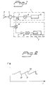
- the radar unit shown in figure 1 includes a transmitter [1] and a receiver [2].
- An antenna [3] is connected to the transmitter and the receiver via a circulator [4].
- an oscillator control device [5] connected to an oscillator [6] with variable frequency.
- the frequency sweep from the oscillator control device [5] controls the oscillator [6] so that a signal is generated with periodically varying frequency, which signal is transmitted by the antenna [3] via a direction coupler [7] and the circulator [4].
- the period of a frequency sweep see figure 2 , has principally three parts in the form of a constant base frequency [30], a linear frequency sweep [31] and a quick return [32] to the base frequency.
- the oscillator [6] can work within the Gigahertz range, e.g. 77 GHz.
- the reflected signal received by the antenna [3] is taken via the circulator to a mixer [8], where the reflected signal is combined with the transmitted signal.
- a difference signal or beat signal is obtained that is used as the basis for the subsequent signal processing for detecting and eliminating interference and synthesis of the useable signal without interference in a processor block [11] that can also contain what is known as an FFT processor [11'].
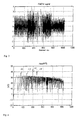
- Figure 3 shows 1024 samples of an FMCW beat signal (time signal) that is simulated as a number of sine/cosine signals + Gaussian noise + an interference. It is difficult by eye to locate and characterise accurately the interference.
- Figure 4 which shows the absolute amount of the FFT for the beat signal in figure 3 , shows four distinct peaks [12], [13], [14] and [15] above a high noise base. Each peak [12] - [15] corresponds to a target. Nor in figure 4 is it possible to characterise the interference.
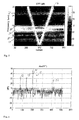
- Figure 5 shows the result of a time-frequency analysis of the beat signal in figure 3 .
- STFT on 64 samples one at a time with overlaps has been used. From figure 5 it appears directly from the V [16] that can be seen in the centre of the signal that the interference is a linear chirp.
- the explanation for the chirp being a V and not just a line is that the FFT analysis used cannot distinguish between positive and negative frequencies.
- the dominant peaks in the spectrum appear as horizontal bands [17] - [21] corresponding to standing sine waves with constant frequency.
- the frequency resolution is quite coarse and the two peaks [14], [15] in figure 4 move partly together into a single broad band [19], [20].
- a horizontal band [21] at approximately 0.8*Nyqvist frequency does not correspond to any peak in figure 4 .
- Figure 5 shows as stated previously that a chirp appears as a V, labelled [16], in an STFT division.
- a pulse appears as a vertical line localised in time but broad-band.
- the useable signals are, however, horizontal lines. It is therefore possible to detect interference of the pulse or linear chirp type by looking in an STFT image for lines that are not parallel with the time axis.
- Such methods are known from image processing, see for example the Gonzalez/Woods reference mentioned above. A suitable method in this connection is described in chapter 7 in this reference and is based on what is known as Hough Transform.
- the useable signal in an FMCW radar unit i.e. the signal that corresponds to the actual target, is a sum of sine waves.
- T the sampling interval.
- corresponding filters can be created by multiplication of second order FIR filters.
- a signal that is the sum of four different sine waves, i.e. an FMCW signal with four strong targets, can thus be reduced to zero by an FIR filter of order 8 and a sample can be predicted linearly from the 8 preceding ones.
- point 1 The application of point 1 is that the sensitivity of the detection of an interference is greatly increased if the useable signal is pre-fittered in a suitable way. In figure 5 this corresponds to the horizontal bands being filtered away. Only the interference then remains against a weak background. This permits the detection of interference with an amplitude that is much lower than that of the useable signal, e.g. a signal that is completely invisible by analysis of the amplitudes in figure 3 but that still increases the noise base in the FFT in figure 6 .
- Point 2 makes it possible to interpolate the useable signal past a short section with interference, which will be described in greater detail later on.
- a "suitable” filter can be calculated in various ways, or calculated as an adaptive filter. Both problems according to point 1 and point 2 above are known from adaptive signal treatment, see for example Haykin, Adaptive Filter Theory, 2nd Ed., Prentice-Hall 1991 .
- the coefficients can be determined by the usual algorithms, e.g. LMS, standardised LMS, RLS, etc, see in particular chapters 9 and 13 in the above reference.
- a usual method of attenuating interference is to detect interference, e.g. a pulse, by the signal amplitude being unusually large and then to carry out clipping of the signal, preferably to the level 0. This can in itself eliminate the interference, but affects the FFT adversely by also affecting the useable signal.
- the precondition for an FFT is that the sample is sampled equidistantly over a suitable period. Clipping of the signal removes samples. It can be said that the time base of the useable signal is affected. A consequence is that distinct targets are widened in the Fourier domain, which among other things can result in a reduction in the resolution.
- a very useful method is to follow up the interference elimination by a synthesis of the useable signal.
- point 2 above can be used.
- the synthesis can consist of an extrapolation (one-ended) or interpolation (two-ended) of the signal based on values without interference. Such a synthesis can result in a dramatic improvement in the reconstruction of the FMCW signal without interference and its FFT.
- the polynomial of the interpolation/extrapolation can as mentioned above be determined adaptively or in another way.
- the interpolation is particularly simple if the signal is narrow-band, as an interpolation polynomial of low order is usually sufficient.
- the interpolation/extrapolation is numerically sensitive, among other things on account of the fact that the roots of the polynomial of the extrapolation lie on or near the unit circle and numerical interference therefore does not die out, and can also for other reasons only be carried out over short sections of time. It is therefore not possible simply to interpolate/extrapolate past a chirp of a certain length.
Landscapes
- Engineering & Computer Science (AREA)
- Radar, Positioning & Navigation (AREA)
- Remote Sensing (AREA)
- Computer Networks & Wireless Communication (AREA)
- Physics & Mathematics (AREA)
- General Physics & Mathematics (AREA)
- Radar Systems Or Details Thereof (AREA)
Claims (1)
- Verfahren zur Erfassung von Interferenzen in Form von Pulsen und linearen Chirps in einer FMCW-Radareinheit mit linearem Frequenzgang zur Erfassung von Zielen, wobei gesendete und empfangene Signale kombiniert werden, um ein Differenzsignal zu bilden, das Schwebungssignal, mit einer Welle für jedes Ziel, wobei die Frequenz, Amplitude und Phase der Welle Information über das Ziel enthalten, dadurch gekennzeichnet, dass das Verfahren die Schritte aufweist(a) Unterziehen des Differenzsignals einer Zeit-Frequenzteilung, die durch eine Kurzzeit-Fourier-Transformierung (STFT) durchgeführt wird, und(b) Erfassen von Interferenzen in dem gewandelten Signal, das durch eine Hough-Transformation transformiert wurde, zum Erfassen von geraden Linien in einem STFT-Bild, die nicht parallel zur Zeitachse sind.
Applications Claiming Priority (7)
| Application Number | Priority Date | Filing Date | Title |
|---|---|---|---|
| SE9603810 | 1996-10-17 | ||
| SE9603810A SE507857C2 (sv) | 1996-10-17 | 1996-10-17 | Förfarande för störningseliminering i en radar av FMCW-typ |
| SE9604775A SE9604775L (sv) | 1996-12-20 | 1996-12-20 | Förfarande för störningseliminering i en radar |
| SE9604775 | 1996-12-20 | ||
| SE9604774A SE9604774L (sv) | 1996-12-20 | 1996-12-20 | Förfarande för störningseliminering i en radar |
| SE9604774 | 1996-12-20 | ||
| PCT/SE1997/001732 WO1998016846A1 (en) | 1996-10-17 | 1997-10-16 | Procedure for the elimination of interference in a radar unit of the fmcw type |
Publications (2)
| Publication Number | Publication Date |
|---|---|
| EP0932837A1 EP0932837A1 (de) | 1999-08-04 |
| EP0932837B1 true EP0932837B1 (de) | 2012-07-25 |
Family
ID=27355846
Family Applications (3)
| Application Number | Title | Priority Date | Filing Date |
|---|---|---|---|
| EP97909816A Expired - Lifetime EP0932838B1 (de) | 1996-10-17 | 1997-10-16 | Verfahren zur störungsunterdrückung in einem fmcw-radar |
| EP97909817A Ceased EP0932839A1 (de) | 1996-10-17 | 1997-10-16 | Verfahren zur störungsunterdrückung in einem fmcw-radar |
| EP97909815A Expired - Lifetime EP0932837B1 (de) | 1996-10-17 | 1997-10-16 | Verfahren zur störungsunterdrückung in einem fmcw-radar |
Family Applications Before (2)
| Application Number | Title | Priority Date | Filing Date |
|---|---|---|---|
| EP97909816A Expired - Lifetime EP0932838B1 (de) | 1996-10-17 | 1997-10-16 | Verfahren zur störungsunterdrückung in einem fmcw-radar |
| EP97909817A Ceased EP0932839A1 (de) | 1996-10-17 | 1997-10-16 | Verfahren zur störungsunterdrückung in einem fmcw-radar |
Country Status (8)
| Country | Link |
|---|---|
| US (3) | US6469662B2 (de) |
| EP (3) | EP0932838B1 (de) |
| JP (1) | JP2001502425A (de) |
| KR (1) | KR100488028B1 (de) |
| AU (3) | AU4733097A (de) |
| DE (1) | DE69737354T2 (de) |
| ES (1) | ES2387612T3 (de) |
| WO (3) | WO1998016847A1 (de) |
Cited By (1)
| Publication number | Priority date | Publication date | Assignee | Title |
|---|---|---|---|---|
| WO2020041891A1 (en) * | 2018-08-30 | 2020-03-05 | Atomic Energy Of Canada Limited / Énergie Atomique Du Canada Limitée | Continuous wave ultrasound or acoustic non-destructive testing |
Families Citing this family (79)
| Publication number | Priority date | Publication date | Assignee | Title |
|---|---|---|---|---|
| JP3622565B2 (ja) * | 1999-03-31 | 2005-02-23 | 株式会社デンソー | レーダ装置 |
| DE19925216C1 (de) * | 1999-06-01 | 2001-01-04 | Siemens Ag | Verfahren zur störsignalfreien Auswertung von Radarsignalen |
| JP4111667B2 (ja) * | 2000-09-26 | 2008-07-02 | 富士通テン株式会社 | Fm−cwレーダ装置 |
| JP4120692B2 (ja) * | 2004-05-11 | 2008-07-16 | 株式会社村田製作所 | レーダ |
| US7474257B2 (en) * | 2004-11-08 | 2009-01-06 | The United States Of America As Represented By The Secretary Of The Navy | Multistatic adaptive pulse compression method and system |
| US7403153B2 (en) * | 2004-12-15 | 2008-07-22 | Valeo Raytheon Systems, Inc. | System and method for reducing a radar interference signal |
| WO2006123500A1 (ja) * | 2005-05-16 | 2006-11-23 | Murata Manufacturing Co., Ltd. | レーダ |
| JP4825574B2 (ja) * | 2005-05-18 | 2011-11-30 | 株式会社東芝 | レーダ装置 |
| JP4293194B2 (ja) * | 2005-09-02 | 2009-07-08 | 財団法人雑賀技術研究所 | 距離測定装置、及び距離測定方法 |
| US7590209B2 (en) | 2005-12-30 | 2009-09-15 | L3 Communications Integrated Systems L.P. | Method and computer program for identifying a transition in a phase-shift keying or frequency-shift keying signal |
| US8059026B1 (en) * | 2006-03-01 | 2011-11-15 | The United States Of America As Represented By The Secretary Of The Air Force | Interference avoiding transform domain radar |
| DE102006024458B4 (de) | 2006-05-24 | 2016-04-14 | Infineon Technologies Ag | Integrierte Mehrfachmischer-Schaltung |
| DE102006024460B4 (de) | 2006-05-24 | 2016-08-04 | Infineon Technologies Ag | Vorrichtung und Verfahren zur Durchführung eines Tests |
| DE102006024457B4 (de) | 2006-05-24 | 2014-06-05 | Infineon Technologies Ag | Integrierte Schaltung zum Senden und/oder Empfangen von Signalen |
| RU2319168C1 (ru) * | 2006-08-09 | 2008-03-10 | Открытое акционерное общество "Корпорация "Фазотрон-Научно-исследовательский институт радиостроения" | Устройство компенсации сигналов, принимаемых по боковым лепесткам (варианты) |
| JP4492628B2 (ja) * | 2007-03-20 | 2010-06-30 | 株式会社デンソー | 干渉判定方法,fmcwレーダ |
| US7612707B2 (en) | 2007-09-28 | 2009-11-03 | Banner Engineering Corporation | Configurable radar sensor |
| JP2010014488A (ja) * | 2008-07-02 | 2010-01-21 | Fujitsu Ltd | Fmcwレーダ装置用信号処理装置、fmcwレーダ装置用信号処理方法、fmcwレーダ装置 |
| JP5110531B2 (ja) * | 2008-07-24 | 2012-12-26 | 日本無線株式会社 | Fm−cwレーダ装置 |
| US7791528B2 (en) * | 2008-11-24 | 2010-09-07 | Autoliv Asp, Inc. | Method and apparatus for radar signal processing |
| US7982666B2 (en) * | 2009-03-10 | 2011-07-19 | Lockheed Martin Corporation | System and method for increasing spectral resolution |
| US7773029B1 (en) * | 2009-03-10 | 2010-08-10 | Lockheed Martin Corporation | System and method for filtering clutter |
| CN102121991B (zh) * | 2010-01-08 | 2013-01-23 | 郑州威科姆科技股份有限公司 | 基于北斗一代卫星信号接收的干扰抑制方法及装置 |
| KR101135982B1 (ko) * | 2010-04-14 | 2012-04-17 | 국방과학연구소 | 주파수 변조 연속파 레이다에서 간섭 제거를 위한 시스템 간 동기화 방법 |
| EP2391022B1 (de) | 2010-05-27 | 2012-10-24 | Mitsubishi Electric R&D Centre Europe B.V. | Klassifizierung von Störungen |
| EP2390679B1 (de) * | 2010-05-27 | 2012-10-03 | Mitsubishi Electric R&D Centre Europe B.V. | Automobilradar mit Funkfrequenzstörungsvermeidung |
| KR101759975B1 (ko) * | 2011-01-03 | 2017-07-24 | 팅크웨어(주) | 전자 기기 및 전자 기기의 차선 이탈 경보 방법 |
| EP2492709A1 (de) * | 2011-02-25 | 2012-08-29 | Nederlandse Organisatie voor toegepast -natuurwetenschappelijk onderzoek TNO | FMCW-Radarsystem |
| NO335171B1 (no) * | 2011-10-07 | 2014-10-13 | 3D Radar As | Adaptiv interferensundertrykkelse for georadar |
| EP2811908A4 (de) * | 2012-02-11 | 2015-10-28 | Sensifree Ltd | Kontaktloser mikrowellenherzfrequenzsensor |
| DE102012021212A1 (de) | 2012-10-27 | 2014-04-30 | Valeo Schalter Und Sensoren Gmbh | Verfahren zur Detektion einer Interferenz in einem Empfangssignal eines Radarsensors, Fahrerassistenzeinrichtung und Kraftfahrzeug |
| DE102012021239A1 (de) | 2012-10-27 | 2014-04-30 | Valeo Schalter Und Sensoren Gmbh | Verfahren zur Detektion einer Interferenz in einem Empfangssignal eines Radarsensors, Fahrassistenzeinrichtung und Kraftfahrzeug |
| DE102012021240A1 (de) | 2012-10-27 | 2014-04-30 | Valeo Schalter Und Sensoren Gmbh | Verfahren zum Unterdrücken einer Interferenz in einem Empfangssignal einesRadarsensors eines Kraftfahrzeugs und entsprechende Fahrerassistenzeinrichtung |
| US9671488B2 (en) * | 2013-03-12 | 2017-06-06 | Rosemount Tank Radar Ab | Radar level gauge with signal division |
| KR101465370B1 (ko) * | 2013-12-09 | 2014-11-26 | 한국항공우주연구원 | 위상누적다항식을 이용하여 양방향 첩신호를 생성하는 장치 및 방법 |
| DE102014114110A1 (de) * | 2014-09-29 | 2016-03-31 | Hella Kgaa Hueck & Co. | Radarsensor |
| US9952312B2 (en) | 2015-07-06 | 2018-04-24 | Navico Holding As | Radar interference mitigation |
| EP3173812B1 (de) | 2015-11-24 | 2021-01-06 | Veoneer Sweden AB | Kraftfahrzeug-radarsystem zur verringerung von interferenzen |
| JP6678022B2 (ja) * | 2015-12-11 | 2020-04-08 | 古野電気株式会社 | 探知装置、水中探知装置、及びレーダ装置 |
| US9846228B2 (en) | 2016-04-07 | 2017-12-19 | Uhnder, Inc. | Software defined automotive radar systems |
| US10261179B2 (en) | 2016-04-07 | 2019-04-16 | Uhnder, Inc. | Software defined automotive radar |
| US9689967B1 (en) | 2016-04-07 | 2017-06-27 | Uhnder, Inc. | Adaptive transmission and interference cancellation for MIMO radar |
| US11002829B2 (en) * | 2016-04-15 | 2021-05-11 | Mediatek Inc. | Radar interference mitigation method and apparatus |
| WO2017187299A2 (en) | 2016-04-25 | 2017-11-02 | Uhnder, Inc. | Successive signal interference mitigation |
| US9599702B1 (en) | 2016-04-25 | 2017-03-21 | Uhnder, Inc. | On-demand multi-scan micro doppler for vehicle |
| US9945935B2 (en) | 2016-04-25 | 2018-04-17 | Uhnder, Inc. | Digital frequency modulated continuous wave radar using handcrafted constant envelope modulation |
| WO2017187306A1 (en) | 2016-04-25 | 2017-11-02 | Uhnder, Inc. | Adaptive filtering for fmcw interference mitigation in pmcw radar systems |
| US10573959B2 (en) | 2016-04-25 | 2020-02-25 | Uhnder, Inc. | Vehicle radar system using shaped antenna patterns |
| US9772397B1 (en) | 2016-04-25 | 2017-09-26 | Uhnder, Inc. | PMCW-PMCW interference mitigation |
| US9791551B1 (en) | 2016-04-25 | 2017-10-17 | Uhnder, Inc. | Vehicular radar system with self-interference cancellation |
| US9575160B1 (en) | 2016-04-25 | 2017-02-21 | Uhnder, Inc. | Vehicular radar sensing system utilizing high rate true random number generator |
| US9954955B2 (en) | 2016-04-25 | 2018-04-24 | Uhnder, Inc. | Vehicle radar system with a shared radar and communication system |
| US9753121B1 (en) | 2016-06-20 | 2017-09-05 | Uhnder, Inc. | Power control for improved near-far performance of radar systems |
| US10353062B2 (en) * | 2016-07-13 | 2019-07-16 | Texas Instruments Incorporated | Methods and apparatus for narrowband ranging systems using reference signal interpolation |
| WO2018051288A1 (en) | 2016-09-16 | 2018-03-22 | Uhnder, Inc. | Virtual radar configuration for 2d array |
| US11588567B2 (en) * | 2016-12-02 | 2023-02-21 | Texas Instruments Incorporated | Synchronizing vehicle devices over a controller area network |
| WO2018146530A1 (en) | 2017-02-10 | 2018-08-16 | Uhnder, Inc. | Reduced complexity fft-based correlation for automotive radar |
| US9971020B1 (en) | 2017-02-10 | 2018-05-15 | Uhnder, Inc. | Radar data buffering |
| US11454697B2 (en) | 2017-02-10 | 2022-09-27 | Uhnder, Inc. | Increasing performance of a receive pipeline of a radar with memory optimization |
| KR102401188B1 (ko) | 2017-08-28 | 2022-05-24 | 삼성전자주식회사 | 차량의 레이더를 이용한 오브젝트 검출 방법 및 장치 |
| IL255982A (en) * | 2017-11-29 | 2018-01-31 | Arbe Robotics Ltd | Detection, mitigation and prevention of mutual interference between fixed water radars in vehicles |
| US11105890B2 (en) | 2017-12-14 | 2021-08-31 | Uhnder, Inc. | Frequency modulated signal cancellation in variable power mode for radar applications |
| US10718860B2 (en) * | 2018-01-11 | 2020-07-21 | Infineon Technologies Ag | System and method to improve range accuracy in FMCW radar using FSK modulated chirps |
| US12386029B2 (en) | 2018-01-29 | 2025-08-12 | Robert Bosch Gmbh | Millimeter wave automotive radar systems |
| DE102018108648B4 (de) * | 2018-04-11 | 2021-11-11 | Infineon Technologies Ag | Fmcw radar mit störsignalunterdrückung |
| IL259190A (en) * | 2018-05-07 | 2018-06-28 | Arbe Robotics Ltd | System and method of fmcw time multiplexed mimo imaging radar using multi-band chirps |
| EP3637127B1 (de) * | 2018-10-12 | 2024-11-27 | Axis AB | Verfahren, vorrichtung und system zur interferenzreduktion in einer frequenzmodulierten dauerstrichradareinheit |
| US11474225B2 (en) | 2018-11-09 | 2022-10-18 | Uhnder, Inc. | Pulse digital mimo radar system |
| US11681017B2 (en) | 2019-03-12 | 2023-06-20 | Uhnder, Inc. | Method and apparatus for mitigation of low frequency noise in radar systems |
| EP3770628A1 (de) * | 2019-07-24 | 2021-01-27 | Veoneer Sweden AB | Verfahren zur radarinterferenzabschwächung |
| EP3822663B1 (de) | 2019-11-15 | 2022-02-23 | Axis AB | Verfahren, computerprogrammprodukt, vorrichtung und frequenzmoduliertes dauerstrichradarsystem |
| US11953615B2 (en) | 2020-01-13 | 2024-04-09 | Uhnder Inc. | Method and system for antenna array calibration for cross-coupling and gain/phase variations in radar systems |
| DE112020006709T5 (de) * | 2020-02-12 | 2022-12-01 | Denso Corporation | Radarvorrichtung |
| JP7652579B2 (ja) * | 2021-02-05 | 2025-03-27 | 古野電気株式会社 | レーダ信号処理装置、レーダ装置、レーダ信号処理方法およびレーダ信号処理プログラム |
| US12474443B2 (en) * | 2021-04-30 | 2025-11-18 | Nxp B.V. | Radar communication with interference suppression |
| EP4155756A1 (de) | 2021-09-27 | 2023-03-29 | Infineon Technologies AG | Fmcw-radar |
| WO2023100108A1 (en) | 2021-12-02 | 2023-06-08 | Uhnder, Inc. | Radar system with enhanced processing for increased contrast ratio, improved angular separability and elimination of ghost targets |
| JP7769586B2 (ja) * | 2022-05-02 | 2025-11-13 | 株式会社デンソー | レーダ装置 |
| JP7719036B2 (ja) * | 2022-06-14 | 2025-08-05 | 株式会社デンソー | 信号処理装置、および、レーダシステム |
Family Cites Families (18)
| Publication number | Priority date | Publication date | Assignee | Title |
|---|---|---|---|---|
| US36095A (en) * | 1862-08-05 | Improvement in funnel pleasures | ||
| FR2380557A1 (fr) | 1977-02-09 | 1978-09-08 | Int Standard Electric Corp | Systeme de guidage a pseudo-bruit avec rejet des fuites d'emetteur |
| DE3116612A1 (de) * | 1981-04-27 | 1982-11-11 | Siemens AG, 1000 Berlin und 8000 München | Puls-doppler-radarempfaenger mit einer schaltung zur wiederherstellung des ungestoerten signalverlaufs |
| US4692766A (en) * | 1985-09-25 | 1987-09-08 | Rolfs John C | Linearizer frequency discriminator for frequency modulated radar transmitters |
| FR2600778B1 (fr) | 1986-06-27 | 1988-09-02 | Trt Telecom Radio Electr | Dispositif radar pour mesurer la distance qui le separe d'une surface |
| US4743910A (en) * | 1986-12-16 | 1988-05-10 | Hughes Aircraft Company | Frequency domain, pulse compression radar apparatus for eliminating clutter |
| GB2218293A (en) * | 1988-05-04 | 1989-11-08 | Philips Electronic Associated | Continuous wave radar receiver and apparatus |
| GB2235346B (en) * | 1989-08-25 | 1994-01-05 | Marconi Co Ltd | Radar receiver |
| GB2248359A (en) * | 1990-09-26 | 1992-04-01 | Philips Electronic Associated | Resolving range/Doppler coupling in a swept-frequency radar |
| JP2787855B2 (ja) * | 1991-06-28 | 1998-08-20 | 三菱電機株式会社 | 不要信号抑圧装置 |
| US5179542A (en) | 1991-12-31 | 1993-01-12 | Raytheon Company | Signal processor |
| US5294933A (en) * | 1993-01-29 | 1994-03-15 | Westinghouse Electric Corp. | Wideband radar system utilizing adaptive interference canceler |
| US5381357A (en) * | 1993-05-28 | 1995-01-10 | Grumman Corporation | Complex adaptive fir filter |
| JP2989428B2 (ja) | 1993-06-17 | 1999-12-13 | 本田技研工業株式会社 | 時分割型fmレーダシステム |
| GB9401361D0 (en) * | 1994-01-25 | 1994-03-23 | Philips Electronics Uk Ltd | A radar system |
| SE503650C2 (sv) * | 1994-11-10 | 1996-07-22 | Hans Hellsten | Sätt att vid en radar förbättra radardata |
| JP3347571B2 (ja) * | 1996-03-12 | 2002-11-20 | 富士通株式会社 | レーダ装置 |
| USH1720H (en) * | 1997-03-31 | 1998-04-07 | Chen; Victor C. | Time frequency processor for radar imaging of moving targets |
-
1997
- 1997-10-16 AU AU47330/97A patent/AU4733097A/en not_active Abandoned
- 1997-10-16 US US09/269,567 patent/US6469662B2/en not_active Expired - Lifetime
- 1997-10-16 AU AU47328/97A patent/AU4732897A/en not_active Abandoned
- 1997-10-16 JP JP10518281A patent/JP2001502425A/ja active Pending
- 1997-10-16 EP EP97909816A patent/EP0932838B1/de not_active Expired - Lifetime
- 1997-10-16 WO PCT/SE1997/001733 patent/WO1998016847A1/en not_active Ceased
- 1997-10-16 DE DE69737354T patent/DE69737354T2/de not_active Expired - Lifetime
- 1997-10-16 WO PCT/SE1997/001734 patent/WO1998016848A1/en not_active Ceased
- 1997-10-16 ES ES97909815T patent/ES2387612T3/es not_active Expired - Lifetime
- 1997-10-16 US US09/269,565 patent/US6191726B1/en not_active Expired - Lifetime
- 1997-10-16 EP EP97909817A patent/EP0932839A1/de not_active Ceased
- 1997-10-16 KR KR10-1999-7003224A patent/KR100488028B1/ko not_active Expired - Lifetime
- 1997-10-16 US US09/269,562 patent/US6121918A/en not_active Expired - Lifetime
- 1997-10-16 WO PCT/SE1997/001732 patent/WO1998016846A1/en not_active Ceased
- 1997-10-16 AU AU47329/97A patent/AU4732997A/en not_active Abandoned
- 1997-10-16 EP EP97909815A patent/EP0932837B1/de not_active Expired - Lifetime
Cited By (2)
| Publication number | Priority date | Publication date | Assignee | Title |
|---|---|---|---|---|
| WO2020041891A1 (en) * | 2018-08-30 | 2020-03-05 | Atomic Energy Of Canada Limited / Énergie Atomique Du Canada Limitée | Continuous wave ultrasound or acoustic non-destructive testing |
| US12270889B2 (en) | 2018-08-30 | 2025-04-08 | Atomic Energy Of Canada Limited/Ènergie Atomique Du Canada Limitèe | Continuous wave ultrasound or acoustic non-destructive testing |
Also Published As
| Publication number | Publication date |
|---|---|
| US6469662B2 (en) | 2002-10-22 |
| WO1998016848A1 (en) | 1998-04-23 |
| EP0932839A1 (de) | 1999-08-04 |
| DE69737354D1 (de) | 2007-03-29 |
| WO1998016846A1 (en) | 1998-04-23 |
| US6121918A (en) | 2000-09-19 |
| EP0932838A1 (de) | 1999-08-04 |
| DE69737354T2 (de) | 2007-10-31 |
| KR20000049137A (ko) | 2000-07-25 |
| AU4732897A (en) | 1998-05-11 |
| US6191726B1 (en) | 2001-02-20 |
| ES2387612T3 (es) | 2012-09-27 |
| JP2001502425A (ja) | 2001-02-20 |
| EP0932837A1 (de) | 1999-08-04 |
| EP0932838B1 (de) | 2007-02-14 |
| US20020027522A1 (en) | 2002-03-07 |
| AU4732997A (en) | 1998-05-11 |
| WO1998016847A1 (en) | 1998-04-23 |
| AU4733097A (en) | 1998-05-11 |
| KR100488028B1 (ko) | 2005-05-09 |
Similar Documents
| Publication | Publication Date | Title |
|---|---|---|
| EP0932837B1 (de) | Verfahren zur störungsunterdrückung in einem fmcw-radar | |
| EP3816665B1 (de) | Störungsunterdrückung in einem fmcw-radarsystem | |
| EP1672379B1 (de) | System und Verfahren zur Verminderung eines Radarstörsignals | |
| US8259003B2 (en) | High duty cycle radar with near/far pulse compression interference mitigation | |
| US5539412A (en) | Radar system with adaptive clutter suppression | |
| US7683827B2 (en) | System and method for reducing the effect of a radar interference signal | |
| AU630029B2 (en) | Computed-interferometry radar detection method with coherent integration | |
| US4916452A (en) | Process for range measurement with a pulse radar of high pulse repetition frequency | |
| US6097669A (en) | Wavelet filtering of sodar signals | |
| Ellingson et al. | Mitigation of radar interference in L-band radio astronomy | |
| US5565872A (en) | System and method for detecting and characterizing vibrating targets | |
| RU2296345C2 (ru) | Способ разрешения целей по дальности радиолокационной станцией и импульсная радиолокационная станция со сжатием импульсов и восстановлением сигналов | |
| JP3773779B2 (ja) | レーダ信号処理装置 | |
| US11391832B2 (en) | Phase doppler radar | |
| Ashry et al. | Comparative analysis between SAR pulse compression techniques | |
| RU2792418C1 (ru) | Многоканальное устройство обработки фазоманипулированных радиолокационных сигналов | |
| SE507857C2 (sv) | Förfarande för störningseliminering i en radar av FMCW-typ | |
| Foxt et al. | Sonar and Radar Wange-Doppler Processing Using a Cone-Shaped Kernel Time-Frequency Representation | |
| Rosłoniec | Basic Methods for Eliminating Spurious Signals | |
| She et al. | Investigation on low-angle tracking technique for HRR radar | |
| Repesh | Broadband FIR Moving-Target Indicator Radar Filters for Low-PRF Applications | |
| Zhang et al. | The dechirp method for countering the velocity-gate pull off | |
| Chandraiah et al. | ATMOSPHERIC RADAR SIGNAL PROCESSING USING HYBRID WINDOW FUNCTIONS. | |
| Abramson | SIMULATION MODEL OF A TWT-RADAR | |
| Mudukutore et al. | Simulation and analysis of pulse compression for weather radars |
Legal Events
| Date | Code | Title | Description |
|---|---|---|---|
| PUAI | Public reference made under article 153(3) epc to a published international application that has entered the european phase |
Free format text: ORIGINAL CODE: 0009012 |
|
| 17P | Request for examination filed |
Effective date: 19990505 |
|
| AK | Designated contracting states |
Kind code of ref document: A1 Designated state(s): DE ES FR GB IT |
|
| 17Q | First examination report despatched |
Effective date: 20040316 |
|
| APBN | Date of receipt of notice of appeal recorded |
Free format text: ORIGINAL CODE: EPIDOSNNOA2E |
|
| APBR | Date of receipt of statement of grounds of appeal recorded |
Free format text: ORIGINAL CODE: EPIDOSNNOA3E |
|
| APAF | Appeal reference modified |
Free format text: ORIGINAL CODE: EPIDOSCREFNE |
|
| RAP1 | Party data changed (applicant data changed or rights of an application transferred) |
Owner name: SAAB AB |
|
| APBT | Appeal procedure closed |
Free format text: ORIGINAL CODE: EPIDOSNNOA9E |
|
| REG | Reference to a national code |
Ref country code: DE Ref legal event code: R079 Ref document number: 69740444 Country of ref document: DE Free format text: PREVIOUS MAIN CLASS: G01S0013340000 Ipc: G01S0007350000 |
|
| RIC1 | Information provided on ipc code assigned before grant |
Ipc: G01S 13/34 20060101ALI20111222BHEP Ipc: G01S 7/36 20060101ALI20111222BHEP Ipc: G01S 7/35 20060101AFI20111222BHEP |
|
| GRAP | Despatch of communication of intention to grant a patent |
Free format text: ORIGINAL CODE: EPIDOSNIGR1 |
|
| GRAS | Grant fee paid |
Free format text: ORIGINAL CODE: EPIDOSNIGR3 |
|
| GRAA | (expected) grant |
Free format text: ORIGINAL CODE: 0009210 |
|
| AK | Designated contracting states |
Kind code of ref document: B1 Designated state(s): DE ES FR GB IT |
|
| REG | Reference to a national code |
Ref country code: GB Ref legal event code: FG4D |
|
| REG | Reference to a national code |
Ref country code: DE Ref legal event code: R096 Ref document number: 69740444 Country of ref document: DE Effective date: 20120920 |
|
| REG | Reference to a national code |
Ref country code: ES Ref legal event code: FG2A Ref document number: 2387612 Country of ref document: ES Kind code of ref document: T3 Effective date: 20120927 |
|
| PLBE | No opposition filed within time limit |
Free format text: ORIGINAL CODE: 0009261 |
|
| STAA | Information on the status of an ep patent application or granted ep patent |
Free format text: STATUS: NO OPPOSITION FILED WITHIN TIME LIMIT |
|
| 26N | No opposition filed |
Effective date: 20130426 |
|
| REG | Reference to a national code |
Ref country code: DE Ref legal event code: R097 Ref document number: 69740444 Country of ref document: DE Effective date: 20130426 |
|
| REG | Reference to a national code |
Ref country code: FR Ref legal event code: PLFP Year of fee payment: 19 |
|
| REG | Reference to a national code |
Ref country code: FR Ref legal event code: PLFP Year of fee payment: 20 |
|
| PGFP | Annual fee paid to national office [announced via postgrant information from national office to epo] |
Ref country code: FR Payment date: 20161025 Year of fee payment: 20 Ref country code: GB Payment date: 20161027 Year of fee payment: 20 Ref country code: DE Payment date: 20161027 Year of fee payment: 20 |
|
| PGFP | Annual fee paid to national office [announced via postgrant information from national office to epo] |
Ref country code: IT Payment date: 20161024 Year of fee payment: 20 Ref country code: ES Payment date: 20161026 Year of fee payment: 20 |
|
| REG | Reference to a national code |
Ref country code: DE Ref legal event code: R071 Ref document number: 69740444 Country of ref document: DE |
|
| REG | Reference to a national code |
Ref country code: GB Ref legal event code: PE20 Expiry date: 20171015 |
|
| PG25 | Lapsed in a contracting state [announced via postgrant information from national office to epo] |
Ref country code: GB Free format text: LAPSE BECAUSE OF EXPIRATION OF PROTECTION Effective date: 20171015 |
|
| REG | Reference to a national code |
Ref country code: ES Ref legal event code: FD2A Effective date: 20180508 |
|
| PG25 | Lapsed in a contracting state [announced via postgrant information from national office to epo] |
Ref country code: ES Free format text: LAPSE BECAUSE OF EXPIRATION OF PROTECTION Effective date: 20171017 |