EP0932937B1 - Decodeur reed-solomon optimise et destine a de grands blocs de donnees - Google Patents
Decodeur reed-solomon optimise et destine a de grands blocs de donnees Download PDFInfo
- Publication number
- EP0932937B1 EP0932937B1 EP98930982A EP98930982A EP0932937B1 EP 0932937 B1 EP0932937 B1 EP 0932937B1 EP 98930982 A EP98930982 A EP 98930982A EP 98930982 A EP98930982 A EP 98930982A EP 0932937 B1 EP0932937 B1 EP 0932937B1
- Authority
- EP
- European Patent Office
- Prior art keywords
- error
- polynomial
- processor
- register
- storage register
- Prior art date
- Legal status (The legal status is an assumption and is not a legal conclusion. Google has not performed a legal analysis and makes no representation as to the accuracy of the status listed.)
- Expired - Lifetime
Links
Images


Classifications
-
- H—ELECTRICITY
- H03—ELECTRONIC CIRCUITRY
- H03M—CODING; DECODING; CODE CONVERSION IN GENERAL
- H03M13/00—Coding, decoding or code conversion, for error detection or error correction; Coding theory basic assumptions; Coding bounds; Error probability evaluation methods; Channel models; Simulation or testing of codes
- H03M13/03—Error detection or forward error correction by redundancy in data representation, i.e. code words containing more digits than the source words
- H03M13/05—Error detection or forward error correction by redundancy in data representation, i.e. code words containing more digits than the source words using block codes, i.e. a predetermined number of check bits joined to a predetermined number of information bits
- H03M13/13—Linear codes
- H03M13/15—Cyclic codes, i.e. cyclic shifts of codewords produce other codewords, e.g. codes defined by a generator polynomial, Bose-Chaudhuri-Hocquenghem [BCH] codes
- H03M13/151—Cyclic codes, i.e. cyclic shifts of codewords produce other codewords, e.g. codes defined by a generator polynomial, Bose-Chaudhuri-Hocquenghem [BCH] codes using error location or error correction polynomials
Definitions
- the present invention relates to Reed-Solomon decoders in general, and in particular, to an improved error computation processor for computing the error locations and magnitudes thereof in large data blocks.
- Reed-Solomon codes Two such Reed-Solomon systems are described in chapter 6 of Error Control Coding: Fundamentals and Applications, by S. Lin and D.J. Costello, Jr. (Prentice-Hall, Inc., Englewood Cliffs, N.J. 1983) (hereinafter "Error Control Coding") and in chapter 7 of Theory and Practice of Error Control Codes by R.E. Blahut (Addison-Wesley Publishing Co., Reading, Mass., 1983) (hereinafter "Theory and Practice of Error Control Codes').
- EP-A 0 748 124 discloses a signal processing apparatus and method in which an MPEG-2 data stream is transmitted by which Reed-Solomon codes are used. At the receiving end, the signal is subject to Reed-Solomon decoding and error correction using error correction circuitry. This circuitry computes an error-locator polynomial and error-evaluator polynomial and, after applying a Chien search, computes the magnitudes of the errors at locations that were determined to be in error.
- US 5,537,426 discloses that apparatus for deriving an error position polynomial and a Forney syndrome polynomial of a Galois field. It requires only a single multiplier and a single adder for multiplication over the Galois field.
- Reed-Solomon decoder is found in the transmission of digital compressed video over a terrestrial broadcast, cable, or satellite channel.
- the Grand Alliance GA
- the GA HDTV transmission system uses a specified (207, 187) Reed-Solomon (hereinafter also referred to as "R-S") code for forward error correction.
- R-S Reed-Solomon
- 187 bytes of "payload” data and an additional 20 bytes of error-checking data make up a Reed-Solomon block of 207 bytes.
- approximately 10 percent of the R-S block consists of error-checking data; this is a relatively small percentage of the block data.
- the larger the block size the smaller the block percentage of error-checking data that is needed to meet a given performance requirement. Since the execution time of the decoding process depends only on the amount of error-checking data, a larger block size permits a smaller percentage of the block processing time to be used for error detection and correction at a given processing rate. Conversely, the processing may be performed at a slower rate. This in turn allows a trade-off of processing speed in exchange for simpler, more economical hardware which may be more efficiently implemented on an integrated circuit.
- each receiver or retriever will require such a decoder, and since these may be marketed and sold as consumer products, it is desirable for the design of the decoder to be as simple, efficient and economical as possible.
- a set of cumulative "sums" of the data in a given R-S block is computed; these are called syndromes and are equal in number to the error-checking bytes in the block.
- the location and magnitude of every error in the block is determined using only the syndromes, and will be correct for every block in which the number of bytes in error does not exceed half the number of error-checking bytes.
- the bytes in error can be located within the block and, as each is identified, the error magnitude can be added to the corrupted data to reproduce the original value.
- the syndrome computation must be performed for each data block, and may be done as the data is input to the decoder, using standard methods.
- the final correction must also be performed for the entire block, and once again may be done as the data is output from the decoder, after the error locations and magnitudes have been determined. These computations, however, constitute the most difficult part of the Reed-Solomon decoding process, and typically require complicated hardware to perform.
- a Reed-Solomon decoder architecture which implements the computations of data error locations and magnitudes, given the syndromes for that block, in a very hardware-efficient manner, is provided.
- This architecture is shown to perform a broad class of mathematical operations, in what is known as Galois Field (GF) arithmetic, that are required for Reed-Solomon decoding. It is independent of the means of syndrome computation, and may be used with at least two well-known methods of error correction.
- GF Galois Field
- the error computation processor can compute the error-locator polynomial, the error-evaluator polynomial, and the values of the errors whose location was determined to be in error, utilizing two polynomial storage registers, two element storage registers, one multiplier for performing selected multiplication and division, one adder for performing selected addition and subtraction, one error locator stack, one error value stack, and a syndrome register for storing the syndromes of the large data block.
- the first polynomial storage register may be utilized for storing up to t+1 bytes of the coefficients of the error locator polynomial; the second polynomial storage register may be utilized for storing up to 2t bytes of the coefficients of the error evaluator polynomial and for storing the coefficients of the B(x) polynomial used in the Berlekamp-Massey algorithm, during the execution of the said Berlekamp-Massey algorithm; the first element storage register may be utilized for computation of the discrepancy, for storing the normalized value of the discrepancy, for storing intermediate values during the computation of the individual coefficients of the error evaluator polynomial and for storing the results of the evaluation of the error evaluator polynomial; the second element storage register may be utilized for storing a prior non-zero value of the discrepancy; the error locator stack may be utilized for storing the roots of the error locator polynomial; and the error value stack may be utilized for storing
- Another object of the present invention is to provide an improved Reed Solomon decoder architecture that can be easily integrated into an integrated circuit.
- Another object of the present invention is to provide an improved Reed Solomon decoder that achieves an increase in processing speed.
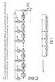
- the Reed-Solomon code specified in the Grand Alliance (GA) standard is shown in Fig. 1. It uses a block length of 207 bytes, 187 of which consist of an MPEG transport packet that constitutes the "payload" data, with the remaining 20 bytes generated by the encoder circuit at the transmitter (not shown).
- This encoder circuit essentially performs a "division" of the data block, which is treated as a degree-206 polynomial over Galois Field GF(256), by a "generator” polynomial (specified for the given R-S code) to generate a "remainder" polynomial that forms the 20 error-checking bytes at the end of the block.
- the circuit is specific to the R-S code used in the GA standard, it nevertheless illustrates the general structure and operation of a known Reed-Solomon encoder; only the block length, number of check bytes, and generator polynomial will be different.
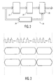
- Fig. 2 depicts a Reed-Solomon decoder generally indicated at 20.
- data entering decoder 20 is input to a syndrome computer 22 and a Reed-Solomon block data delay 24.
- the resulting computed syndromes are input to an error computer 26 from syndrome computer 22.
- Error computer 26 determines the error locations and magnitudes as discussed in greater detail below.
- An error corrector 28 is provided. Error corrector 28 receives as inputs, both the error locations and magnitudes from the error computer 26 and the delayed data from the Reed-Solomon block data delay 24.
- the first step in the decoding process is the syndrome computation. This requires processing of the entire R-S block, independently of the size of the block or the number of check bytes.
- the number of syndromes is equal to the number of check bytes, which in turn increases with the size of the block but becomes a smaller percentage of the block size as this occurs.
- the resulting syndromes are then used to determine the error locations and magnitudes in the block.
- a standard, well-known circuit for performing syndrome computation is described in Error Control Coding, in chapter 6, and page 174 in particular.
- error computer 26 determines the error locations and magnitudes by means of computations employing polynomial arithmetic operations over a Galois field appropriate to the data being transmitted (GF(256) in the case of 8-bit bytes).
- GF(256) in the case of 8-bit bytes.
- an error-locator polynomial must be generated whose roots over GF(256) correspond, respectively, to the location of each detected error within the R-S block. This may be done using any of a number of standard algorithms, of which the Euclidean and the Berlekamp-Massey are the best known.
- Much of the prior art in high-speed Reed-Solomon decoders use the Euclidean algorithm because it is capable of a more rapid computation of the required polynomial.
- the Euclidean algorithm has the disadvantage, however, of requiring a greater amount of hardware for implementation.
- the Berlekamp-Massey algorithm although not as fast, can be implemented with much less hardware because it requires less arithmetic logic and data storage than that required for the Euclidean algorithm. Consequently, a more efficient design is achieved by utilizing the Berlekamp-Massey algorithm.
- the architecture to implement the Berlekamp-Massey algorithm will be discussed in greater detail below as will be the means of optimizing the architecture to reduce the execution time of the algorithm.
- the error-evaluator polynomial Associated with the error-locator polynomial is the error-evaluator polynomial, which is computed using the error-locator polynomial and the syndrome values for the R-S block.
- the two polynomials will subsequently be used to calculate the error magnitudes once the error locations are determined. This is done by finding the roots of the error-locator polynomial (i.e. primitive values in GF(256) which, when substituted for the polynomial variable, give a result of zero), each of which corresponds to the location of an error in the block.
- the finding of the roots is performed using an exhaustive search method known as the Chien Search, where all possible block location values are substituted in the polynomial to determine which ones yield a result of zero.
- the roots of the polynomial are then stored as described below, and the well-known Forney Algorithm is used to compute the error magnitude for each root using the error-locator polynomial and the error-evaluator polynomial. All of the above operations, except for the Chien search which requires dedicated hardware, can be performed using the architecture constructed in accordance with the present invention as described in detail below.
- the maximum length of the two polynomials A(x) and B(x) during a given iteration of the algorithm corresponds to the value of the register length parameter L during that iteration, and not necessarily to the maximum length t + 1 of the registers.
- polynomial shift registers used to implement this algorithm always have the maximum length. This means that, during any iteration, the number of clock cycles required to perform a polynomial operation will always be t + 1 regardless of the actual length of the polynomial in that iteration. Since there are two such operations during each iteration of the algorithm, the result is that 2(t + 1) clock cycles will be used when in fact much fewer may be needed. This degrades the speed of decoding significantly if the clock rate is limited by the hardware, or else will require a faster clock to achieve the desired decoding rate.
- the polynomial processor 60 can overcome this limitation by using the register length parameter L to set the lengths of the two registers, and then creating a "short circuit" from the input to the output of every register element that stores a coefficient of degree higher than L.
- L the number of clock cycles required for the 2t passes of the algorithm is 4t(t+1); using variable-length registers, however, L never exceeds half the number of the current iteration.
- the maximum number of cycles for a given pass becomes 2(L + 1), and the total number of cycles for the algorithm is now the sum of an arithmetic series and equals 2t(t + 3). A reduction in execution time of almost a factor of two is thus achieved. For the GA standard, this equals 260 clock cycles.
- the error-evaluator polynomial ⁇ (x) is the modulo 2t product of the error-locator polynomial computed above and the syndrome polynomial.
- the polynomial processor is capable of performing this computation, especially since the error-locator polynomial already resides in one of the two storage registers 61 and 62 as discussed below (see Fig. 4A), and the error-evaluator polynomial can be written into the second register 62 (with length of 2t).
- Each product coefficient uses every term of the error-locator polynomial, and so requires t+1 clock cycles to compute.
- the error-evaluator polynomial is thus computed in 2t(t+1) clock cycles, which, for the GA standard, equals 220.
- the Berlekamp-Massey algorithm requires two polynomials ⁇ (x) and B(x) (T(x) being utilized for temporary storage and therefore not needed in an actual implementation), and executes for 2t iterations.
- a shift-register architecture that performs the algorithm found at page 186 of Theory and Practice of Error Control Codes is also described therein at page 189.
- a flow chart of a complete Reed-Solomon decoding process is also described in the aforementioned text at page 190.
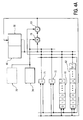
- FIG. 4A depicts an error-computation processor 60 for Reed-Solomon decoding in accordance with the present invention.
- processor 60 performs Galois Field arithmetic on polynomials having maximum length t+1 and 2t, respectively.
- processor 60 as constructed in accordance with the present invention, is optimized both for minimum hardware and minimum computation time.
- processor 60 is designed to store, and to preform mathematical operations on, arithmetic elements of, as well as polynomials over, a Galois Field.
- Such an element may be represented using standard binary numbers (bits), e.g. an element in GF(256) may be represented using 8 bits, or one byte.
- a polynomial over a GF may be represented by its coefficients, each of which is in turn an element of the GF; an n-th degree polynomial may therefore be represented by n+1 such elements. In the case of GF(256) using binary representation, this becomes equivalent to n+1 bytes.
- the 2t syndromes for a Reed-Solomon block are computed in syndrome computer 22 and are deposited in syndrome registers 74.
- Each of these 2t registers 74 stores one syndrome, which is just a GF element.
- the GF(256) syndrome registers thus consist of 2t byte registers. If timing gaps between R-S blocks are not allowed, these registers must receive the results of all 2t syndrome computations at the same time; in this case, 2t distinct registers are required. The reason for this, as may be understood from the timing diagram of Fig.
- the syndrome registers may then be implemented using a register file, or even a small memory, having 2t byte locations.
- the syndrome computations may be performed using any of a number of well-known methods, such as that described in chapter 6 of Error Control Coding .
- the three GF algorithms that are performed by processor 60 are the Berlekamp-Massey (B-M) algorithm for computing the error-locator polynomial, the computation of the error-evaluator polynomial, and the Forney algorithm for computing the error values (the Chien search for computing the error locations is preferably performed by method and construction depicted in Figs. 5A-C.
- the sequence in which these algorithms are performed is described at page 190 of Theory and Practice of Error Control Codes.
- the three algorithms all involve arithmetic computations on GF elements and polynomials.
- processor 60 includes two storage registers 61 and 62 (hereinafter also referred to as registers A and B) for storing GF polynomials, two registers 71 and 72 (hereinafter also referred to as registers X and Y) for storing GF elements, a GF multiplier 78 followed by a GF adder 80, and data busses that allow interconnection of any data source and destination.
- registers A and B two storage registers 61 and 62
- registers 71 and 72 hereinafter also referred to as registers X and Y
- registers X and Y for storing GF elements
- a GF multiplier 78 followed by a GF adder 80
- data busses that allow interconnection of any data source and destination.
- One feature of this architecture is that there are two complete sets of data busses, which permits two simultaneous data transfers between source and destination to take place; this allows certain algorithms as discussed below to complete execution in less time, i. e. fewer clock cycles.
- each of the two element registers 70, 72 may be implemented using byte-storage registers.
- the two polynomial registers 61, 62 may be implemented using multiple-byte storage, with one byte for each coefficient of the stored polynomial.
- the minimum polynomial storage requirement for the three algorithms performed by the error-computation processor consists of one polynomial of degree t (requiring t+1 bytes of register storage), and one of degree 2t-1 (requiring 2t bytes of storage).
- the data busses in the preferred embodiment are 8-bit busses.
- Multiplier 78 and adder 80 each have two 8-bit data inputs and one 8-bit output, and are implemented using standard combinatorial logic that implements their respective operations in GF(256) arithmetic.
- An operation on a polynomial then requires the coefficients to be "circulated" in the storage register so that a new coefficient is output and/or input to the register (depending on whether the polynomial register is a source or a destination or both) every clock cycle, and after a number of clock cycles equal to the length of the register, the coefficients are in their original positions within the register.
- the operations performed on the stored data are multiplication, division, and addition.
- the first two operations are performed by GF multiplier 78 (it is understood that division is achieved by multiplier 78 which may be used as a divider by simply performing an inversion over the GF on the divisor and performing a multiplication of the result and the dividend).
- Addition, performed by adder 80 which, for GF(256) or any other GF of interest, consists of a bitwise exclusive-or of the two byte elements that represent the addend and the augend.
- the configuration of processor 60 allows for, in addition to the above individual operations, the multiplication or division of two elements followed by addition of a third. It is the case that these combinations constitute all of the arithmetic operations on GF elements that are required for any of the three algorithms performed by this architecture.
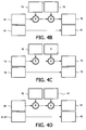
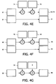
- the Berlekamp-Massey algorithm consists of three separate operations that are performed for each of the 2t iterations of the algorithm. The first of these is the computation of the so-called discrepancy (designated by ⁇ ) (see Fig. 4B), which is determined by the value of the error-locator polynomial (designated by ⁇ (x)) at the current iteration (this polynomial constitutes the final result of the algorithm at the last iteration, and is successively "built up" during the course of the B-M algorithm), and of the 2t syndromes.
- the syndromes are stored in the 2t syndrome storage registers 74, and the coefficients of A(x) are stored in polynomial storage register 61.
- the value of ⁇ in a given iteration, is formed by generating an accumulated sum of products of individual ⁇ (x) coefficients (stored in register 61) and syndromes (stored in register 74), and is stored in element register 70. Since the value of ⁇ (x) is not modified by this operation, its coefficients are read out of register 61 and then written, or "circulated", back into register 61; this permits all of the individual coefficients to be successively accessed, multiplied by the appropriate syndrome, and added to the accumulated sum whose final value, at the end of circulation, constitutes the desired value of ⁇ . In this operation, the use of polynomial register circulation technique is used to achieve the desired results. In the preferred method, register 61 is used as both a source and a destination polynomial register, while register 70 is utilized as both a source and destination element register.
- the second step that occurs in an iteration of the B-M algorithm, when the above discrepancy ⁇ does not equal zero, is its normalization, or division by its previous nonzero value, which is stored in register 72 (see Fig. 4C).
- the new normalized value is stored in register 70, and the old unnormalized value is now stored in register 72 for use in the subsequent normalization.
- the third and final step of the B-M algorithm iteration which once again occurs only when the discrepancy ⁇ is not zero, is the computation of the updated value of the polynomial ⁇ (x) (Fig. 4D), still stored in register 61, based on its current value, the new value of ⁇ (stored in register 70), and of an auxiliary polynomial designated B(x), which is stored in register 62.
- the polynomial B(x) is updated to be the current (although not updated) value of A(x); under other conditions (specified in the Berlekamp-Massey algorithm) it is not updated and re-circulated in register 62.
- the two polynomials are circulated in their respective registers (61 and 62), and each individual coefficient is read and written in one clock cycle.
- the computation of the updated ⁇ (x) consists of multiplying each coefficient of auxiliary polynomial B(x) (in register 62) by the normalized ⁇ (in register 70), and adding the corresponding (i.e. to the same power of x) coefficient of the current ⁇ (x) (in register 61). This is done for every coefficient of ⁇ (x), and the resulting updated coefficients are circulated back into register 61.
- register 61 (consisting of t+1 element registers) stores the error-locator polynomial ⁇ (x)
- register 62 (consisting of 2t element registers) stores the error-evaluator polynomial ⁇ (x).
- Determination of the actual locations of data errors in an R-S block is performed by finding the roots of the error-locator polynomial ⁇ (x), each of which directly corresponds to an error location. This is not performed by error-computation processor 60, but is instead performed by the Chien search, which evaluates the polynomial ⁇ (x) at all possible data location values for the R-S block, so that all which yield a result of zero (i. e. roots of the polynomial) correspond to block errors and are stored, or "pushed", on the error-location stack 66.
- the roots are GF elements, which, in GF(256), are represented as data bytes. Since the R-S code is capable of correcting at most t errors, the error-location stack has a depth of t and a width of 8 bits (1 byte).
- the Chien search for the roots of the error-locator polynomial consists of its evaluation for n values, where n equals the length of the R-S block (207 in the GA standard). This means that each evaluation must be performed very rapidly, hence the polynomial processor cannot be used as it would require t+1 clock cycles per value using Homer's rule as discussed below; hardware is needed to do each evaluation in one cycle, so that the search can be completed in n cycles.
- the circuit shown in detail in Figs.
- 5A-B consists of a set of registers in which the coefficients of the error-locator polynomial are loaded for initialization, and, in each successive clock cycle, the i'th coefficient register contents are multiplied by the i'th power of GF(256) primitive ⁇ . Details of the Chien search can also be found at pages 159-160 of Error Control Coding. The GF(256) sum of all t registers is then generated to determine whether a root has been found. In this event, the root is pushed on top of the stack memory for subsequent use. Computation of the error-evaluator polynomial does not use these roots, and can therefore be performed concurrently with the Chien search after completion of the Berlekamp-Massey algorithm.
- the respective number of clock cycles required is nearly equal (220 vs. 207). If the number of roots found does not equal the degree of the polynomial, an uncorrectable error condition exists. This means that number of errors in the block exceeded t, and the block cannot be corrected. The presence of such a condition indicates that the block is not valid.
- the error location stack 66 is required because the search is initiated with a GF element that corresponds to the last location in the R-S block; consequently, if the block data is to be processed (and corrected) in first-to-last order, it is necessary to reverse the order of the polynomial roots relative to that in which they were evaluated during the search.
- the final algorithm to be performed is the Forney algorithm, which uses the first derivative (in the GF sense) of the error-locator polynomial, as well as the error-evaluator polynomial, both evaluated at each error-locator root that was found by the Chien search and stored in error-location stack 66.
- the Forney algorithm which is used to compute the error magnitudes given the above roots and the two polynomials, is given by the formula described at page 190 of Theory and Practice of Error Control Codes.
- ⁇ (x) must be evaluated for each root x found during the Chien search.
- the derivative of ⁇ (x) is found by taking the sum of the odd-power terms of the polynomial evaluated at x and dividing it by x. Since every term of ⁇ (x) is evaluated during the search, it is a very simple matter to generate the sum of only the odd-power terms and store it concurrently with the root, whenever one is found, in a second stack memory.
- the result is that this algorithm, which commences when both the Chien search and error-evaluator polynomial computation have completed, requires t(2t+1) clock cycles in the worst case of t roots, which equal 210 for the GA standard.
- the first derivative of a polynomial over a GF is the sum of the odd terms of that polynomial. Since the Chien search needs to evaluate all polynomial terms, odd and even, the desired odd terms for every location root are selected from the complete polynomial for that root, and their sum is computed (as was that of all terms in order to find the root) and pushed onto the aforementioned second stack 68, called the error-value stack, that also has a depth of t locations. Both the location roots and their associated polynomial derivatives are now stored in the two stacks, and will be used to compute the actual values of the errors corresponding to each location.
- Fig. 4F depicts the configuration for the evaluation of the error-evaluator polynomial ⁇ (x) at each of the values found by the Chien Search.
- This evaluation is performed by error-computation processor 60 using the polynomial coefficients that were stored in register 62 and the location roots that were stored in the error-location stack 66. This is done for each root by successively multiplying the accumulated product stored in register 70 by the root value stored in the stack, adding the result to the current polynomial coefficient stored in register 62, and storing the resulting new accumulated product back in register 70. This is repeated for all 2t coefficients of ⁇ (x), and the final result of the last iteration is the value of ⁇ (x) evaluated for the location root and is stored in register 70.
- This algorithm for polynomial evaluation is known as Homer's rule.
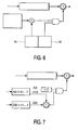
- the actual error correction which takes place after all error locations and magnitudes have been determined, is performed by a circuit such as that shown in Fig. 6. It delays the input R-S block data by two block intervals as described earlier, and uses the errors and magnitudes found in the error computation section and stored in the two stack memories to perform the corrections.
- initialization of the Chien search required that it be performed in reverse order of block locations relative to that in which the data arrived. Therefore, stack memories were used to store the error information, and that stacks are required for the storage of both error locations and values in both the error computation and the error correction sections of the R-S decoder (data must be "pushed" onto the stacks in the error computation steps and "popped" from the stacks in the error-correction steps).
- the two sections can exchange their respective error location and value stacks in a "ping-pong" fashion, so that the error corrector 28 receives the results of the most recent error computation and can then begin to correct a new block, and error computation processor 60 in turn receives discarded error data that may be cleared to make room for new data.
- the GF elements that correspond to each R-S block data location starting with the first location in the data block are generated by a counter that is initialized to the value that corresponds to the beginning of the block, and counts through all of the block locations in the correct (i. e. not reverse) order. This is done by comparing each location value with the contents of the top of the error location stack 66. When the two values are equal, the lambda(x) root at the top of the stack corresponds to the current data byte location in the R-S block. The contents of the top of the data value stack are then added to the data byte in this block location, and in GF(256) arithmetic this consists of a bitwise exclusive-or of the 8 bits of the error value with those of the data byte.
- the two stacks are then popped so that the next error location and value pair is on the top, and the procedure is repeated. This is done for every error location and value pair stored in the stacks until the stacks are empty, at which point all detected errors in the R-S block will have been corrected.
- polynomial storage register 61 which stores ⁇ (x), consists of t+1 element registers for the t+1 coefficients of ⁇ (x).
- Register 62 has a length of t+1 element registers when used to store auxiliary polynomial B(x), but requires 2t elements to store ⁇ (x); it must thus have the capability of being configured for either length; this can be accomplished by using a multiplexer, which selects the element register that corresponds to the coefficient having the polynomial order of the desired length.
- the ability to modify the length of a polynomial storage register is needed in order to eliminate the need for a third register (i. e. two of length t+1 for ⁇ (x) and B(x), and a third for ⁇ (x)), and for the possibility of configuring a polynomial storage register to any desired length.
- Fig. 4H shows a preferred polynomial register storage element that, because of its unique circuit arrangement, permits for the adjustment of the polynomial storage register length.
- the circuit preferably includes, a flip-flop 91 and a multiplexor including an inverter 92, two AND gates 93, 94 and an OR gate 95.
- This configuration allows any storage element in the polynomial register to be effectively “short circuited", thereby reducing the effective length of the register.
- fewer of these elements are "short-circuited", and the polynomial register is thereby "grown" in length as the register length parameter of the B-M algorithm increases in value.
- Control of the register length is performed by the control circuit (not shown) of error-computation processor 60, which implements all control functions of the storage registers, arithmetic units (multiplier/divider and adder), and data paths that must be performed in order to implement the various algorithms.
- error-computation processor 60 implements all control functions of the storage registers, arithmetic units (multiplier/divider and adder), and data paths that must be performed in order to implement the various algorithms.
- the ability to modify the polynomial storage register lengths results in a reduction in the required number of clock cycles of almost one-half. It also reduces the number of clock cycles required to compute the error-evaluator polynomial ⁇ (x) by about one-third.
- a penalty that may be paid for this capability, however, is that, due to the additional complexity of and propagation delays in the data paths, the maximum clock frequency at which the processor can be operated may be reduced.
- Fig. 7 An alternative method of performing the error correction that is used is shown in Fig. 7.
- the error computation consists only of computing the error-locator and error-evaluator polynomials using either the B-M algorithm or some other means (such as the Euclidean algorithm), and the Chien search is performed during the actual error correction using hardware similar to that shown in Figs. 5A-5B.
- this circuit can be used to evaluate both ⁇ (x) and its derivative x ⁇ '(x) simultaneously.
- a similar circuit consisting of 2t-1 registers and GF constant multipliers is used to evaluate ⁇ (x) concurrently.
- the method of Fig. 7 has the advantage, however, of performing all error computations subsequent to the generation of the error locator and evaluator polynomials during the error correction phase and therefore in real time. This means that the error computation phase can be performed in less time (i. e. fewer clock cycles), since the evaluation of the error-evaluator polynomial and the Forney algorithm are no longer performed in the error computation section.
- Processor 60 can be used to compute both of the required polynomials, in the manner described above, once again using a minimum of hardware and clock cycles. Because of the ability of this architecture to perform a wide range of GF operations, however, it can also be used to evaluate all of the individual terms of both polynomials for the R-S block location value that corresponds to the beginning of the block, the Chien search can be started at this location and be performed in the actual block order with no reversal required. Computation of the polynomial terms consists of GF multiplication of each coefficient by the corresponding power of the polynomial variable, which in this case corresponds to the first location of the R-S block.
- the first 2t powers of this first location value may be computed during the design of the decoder, and stored as the polynomial arguments in storage 76 (Fig. 4A). These values are preferably "hard-wired", and can thus be stored in a small (2t byte) read-only memory.
- the polynomial coefficients are stored in their respective storage registers (61 and 62), so that the t+1 terms of the A(x) polynomial and the 2t terms of the ⁇ (x) polynomial may be computed by multiplying each coefficient with the corresponding polynomial argument in storage 76.
- the advantage of this method is that, since the Forney algorithm is not performed as part of the error computation, fewer clock cycles are needed; this can be of value in cases where the R-S block is not very large, as well as when timing gaps are not allowed between R-S blocks.
- a disadvantage is that it requires additional hardware for the rapid evaluation of the ⁇ (x) polynomial and for the initialization of both ⁇ (x) and ⁇ (x), in addition to a second GF divider for the Forney algorithm. It is therefore of value only in limited circumstances, but in some cases the improvement in performance may be sufficient to justify the additional hardware.
- This invention lends itself to efficient implementation on an integrated circuit, and may represent an advancement in the state of Reed-Solomon decoder art for the case of large data blocks.
Landscapes
- Physics & Mathematics (AREA)
- Mathematical Physics (AREA)
- Algebra (AREA)
- General Physics & Mathematics (AREA)
- Pure & Applied Mathematics (AREA)
- Probability & Statistics with Applications (AREA)
- Engineering & Computer Science (AREA)
- Theoretical Computer Science (AREA)
- Error Detection And Correction (AREA)
- Detection And Correction Of Errors (AREA)
Claims (13)
- Processeur de calcul d'erreurs (26) destiné à calculer les positions et grandeurs d'erreurs d'un grand bloc de données présentant un maximum de t erreurs dans un champ de Galois souhaité, et destiné à une utilisation dans un décodeur Reed-Solomon (20), le processeur comprenant :des premiers moyens de calcul destinés à calculer un polynôme de positions d'erreurs et un polynôme d'évaluation d'erreurs, etdes seconds moyens de calcul destinés à calculer les grandeurs des erreurs en des positions déterminées comme présentant une erreur, à l'aide de la première dérivée du polynôme de positions d'erreurs et du polynôme d'évaluation d'erreurs calculés,caractérisé en ce que lesdits premiers et seconds moyens de calcul nécessitent tous deux ensemble uniquement les moyens de calcul et de stockage suivants :un premier registre de stockage de polynômes (61) destiné à stocker des polynômes de champ de Galois;un second registre de stockage de polynômes, différent du premier, destiné à stocker le polynôme de champ de Galois;les registres de stockage de polynômes permettant le réglage de la longueur de registre de stockage de polynômes;un premier registre de stockage d'éléments (71) destiné à stocker des éléments de champ de Galois;un second registre de stockage d'éléments (72), différent du premier, destiné à stocker des éléments de champ de Galois;un multiplicateur (78) destiné à exécuter une multiplication et une division sélectionnées, la division étant exécutée en réalisant une inversion dans le champ de Galois sur le diviseur et en réalisant une multiplication du résultat et du dividende;un circuit d'addition (80) destiné à exécuter l'addition et la soustraction sélectionnées;une pile de positions d'erreurs (66) destinée à stocker des racines du polynôme de positions d'erreurs;une pile de valeurs d'erreurs (68) destinée à stocker la grandeur des erreurs et les dérivées du polynôme de positions d'erreurs, etun registre de syndromes (74) destiné à stocker les syndromes du grand bloc de données.
- Processeur suivant la revendication 1, dans lequel ledit second registre de stockage de polynômes stocke les coefficients d'un polynôme auxiliaire B(x) utilisé dans l'algorithme de Berlekamp-Massey, durant l'exécution dudit algorithme de Berlekamp-Massey.
- Processeur suivant la revendication 1 ou 2, dans lequel ledit premier registre d'éléments de stockage stocke la valeur normalisée de la divergence calculée durant l'exécution de l'algorithme de Berlekamp-Massey.
- Processeur suivant la revendication 1, 2 ou 3, dans lequel ledit premier registre de stockage d'éléments stocke des valeurs intermédiaires durant le calcul des coefficients individuels du polynôme d'évaluation d'erreurs.
- Processeur suivant la revendication 4, dans lequel ledit premier registre de stockage d'éléments stocke les résultats de l'évaluation du polynôme d'évaluation d'erreurs.
- Processeur suivant la revendication 1, 2, 3, 4 ou 5, dans lequel la pile de valeurs d'erreurs stocke la dérivée du polynôme de positions d'erreurs durant une recherche de Chien.
- Processeur suivant l'une quelconque des revendications précédentes, dans lequel le multiplicateur comprend un inverseur destiné à exécuter ladite division sélectionnée.
- Processeur suivant l'une quelconque des revendications précédentes, dans lequel lesdits premier et/ou second registres de stockage de polynômes comprennent une pluralité d'éléments de stockage pour registre de polynômes, chacun d'entre eux comprenant une bascule en série avec un multiplexeur, la longueur du registre de polynômes pouvant ainsi être réglée.
- Processeur suivant l'une quelconque des revendications précédentes, et comprenant des moyens de stockage d'arguments polynomiaux destinés à stocker les éléments GF calculés au préalable, et dans lequel ledit multiplicateur multiplie les éléments GF calculés au préalable par les coefficients de polynômes appropriés du polynôme de positions d'erreurs et du polynôme d'évaluation d'erreurs, de manière à fournir des valeurs initiales des polynômes sans devoir exécuter une inversion sur le bloc Reed-Solomon.
- Processeur suivant la revendication 1, comprenant des moyens pour permettre jusqu'à deux transferts de données simultanés entre des registres source et destinataire.
- Processeur de calcul d'erreurs suivant l'une quelconque des revendications précédentes, dans lequel ledit premier registre de stockage de polynômes stocke jusqu'à t+1 octets des coefficients du polynôme de positions d'erreurs, ledit second registre de stockage de polynômes stocke jusqu'à 2t octets des coefficients du polynôme d'évaluation d'erreurs, ledit premier registre de stockage d'éléments est destiné au calcul de la divergence, ledit second registre de stockage d'éléments est destiné à stocker une valeur non nulle de la divergence, ladite pile de position d'erreurs stocke les racines du polynôme de positions d'erreurs, et ladite pile de valeurs d'erreurs stocke la grandeur de chaque erreur.
- Décodeur Reed-Solomon (20) comprenant:des moyens de calcul de syndrome (22) destinés à recevoir un grand bloc de données présentant un maximum de t erreurs et calculant les syndromes dudit grand bloc de données;un processeur de calcul d'erreurs (26) suivant l'une quelconque des revendications précédentes;des moyens de correction d'erreurs (28) destinés à corriger lesdites erreurs dans ledit grand bloc de données, etun retard de données (24) destiné à retarder la transmission dudit bloc de données vers lesdits moyens de correction d'erreurs.
- Téléviseur comprenant une combinaison reposant sur un décodeur Reed-Solomon (20) suivant la revendication 12 et un décodeur de source vidéo.
Applications Claiming Priority (3)
| Application Number | Priority Date | Filing Date | Title |
|---|---|---|---|
| US08/902,049 US6061826A (en) | 1997-07-29 | 1997-07-29 | Hardware-optimized reed-solomon decoder for large data blocks |
| US902049 | 1997-07-29 | ||
| PCT/IB1998/001108 WO1999007074A2 (fr) | 1997-07-29 | 1998-07-20 | Decodeur reed-solomon optimise et destine a de grands blocs de donnees |
Publications (2)
| Publication Number | Publication Date |
|---|---|
| EP0932937A1 EP0932937A1 (fr) | 1999-08-04 |
| EP0932937B1 true EP0932937B1 (fr) | 2006-05-17 |
Family
ID=25415233
Family Applications (1)
| Application Number | Title | Priority Date | Filing Date |
|---|---|---|---|
| EP98930982A Expired - Lifetime EP0932937B1 (fr) | 1997-07-29 | 1998-07-20 | Decodeur reed-solomon optimise et destine a de grands blocs de donnees |
Country Status (5)
| Country | Link |
|---|---|
| US (1) | US6061826A (fr) |
| EP (1) | EP0932937B1 (fr) |
| JP (1) | JP3970337B2 (fr) |
| DE (1) | DE69834542T2 (fr) |
| WO (1) | WO1999007074A2 (fr) |
Families Citing this family (32)
| Publication number | Priority date | Publication date | Assignee | Title |
|---|---|---|---|---|
| US6484192B1 (en) * | 1998-01-29 | 2002-11-19 | Toyo Communication Equipment Co., Ltd. | Root finding method and root finding circuit of quadratic polynomial over finite field |
| US6154869A (en) * | 1998-02-03 | 2000-11-28 | Texas Instruments Incorporated | Combined error position circuit and chien search circuit for reed-solomon decoding |
| US6637002B1 (en) * | 1998-10-21 | 2003-10-21 | Maxtor Corporation | Decoder for error correcting block codes |
| US6279137B1 (en) * | 1998-12-08 | 2001-08-21 | Lsi Logic Corporation | System and method for a storage-efficient parallel Chien Search |
| US6446233B1 (en) * | 1999-09-10 | 2002-09-03 | Lsi Logic Corporation | Forward error correction apparatus and methods |
| US6543026B1 (en) * | 1999-09-10 | 2003-04-01 | Lsi Logic Corporation | Forward error correction apparatus and methods |
| US20020116679A1 (en) * | 2000-12-15 | 2002-08-22 | Mike Lei | In-band FEC decoder for sonet |
| US6920600B2 (en) * | 2002-01-23 | 2005-07-19 | Thomson Licensing S.A. | Dual chien search blocks in an error-correcting decoder |
| US7020826B2 (en) * | 2002-01-23 | 2006-03-28 | Thomson Licensing | Intra-decoder component block messaging |
| US7421642B2 (en) * | 2002-04-05 | 2008-09-02 | Seagate Technology Llc | Method and apparatus for error detection |
| US20030192005A1 (en) * | 2002-04-05 | 2003-10-09 | Seagate Technology Llc | Method and apparatus for error detection |
| US7032162B1 (en) * | 2002-04-25 | 2006-04-18 | Lattice Semiconductor Corporation | Polynomial expander for generating coefficients of a polynomial from roots of the polynomial |
| US20040078747A1 (en) * | 2002-10-21 | 2004-04-22 | Miller David H. | Generalized forney algorithm circuit |
| US7693927B2 (en) * | 2003-08-25 | 2010-04-06 | Jennic Limited | Data processing system and method |
| KR100594241B1 (ko) * | 2004-01-29 | 2006-06-30 | 삼성전자주식회사 | 순방향 치엔 서치 방식의 리드 솔로몬 디코더 회로 |
| US7467346B2 (en) * | 2005-08-18 | 2008-12-16 | Hitachi Global Storage Technologies Netherlands, B.V. | Decoding error correction codes using a modular single recursion implementation |
| US8064351B2 (en) * | 2005-10-20 | 2011-11-22 | Schrader Electronics, Ltd. | Method for detecting and correcting data errors in an RF data link |
| EP2011568B1 (fr) * | 2006-03-16 | 2016-08-24 | Universidad Tecnica Federico Santa Maria (Usm) | Dispositif d'extraction de composés chimiques organiques à propriétés toxiques présents dans des échantillons atmosphériques, au moyen de solvants chauffés par des micro-ondes focalisées dans des systèmes ouverts (n'ayant pas été mis sous pression) |
| US20080140740A1 (en) * | 2006-12-08 | 2008-06-12 | Agere Systems Inc. | Systems and methods for processing data sets in parallel |
| KR100847560B1 (ko) * | 2006-12-11 | 2008-07-21 | 삼성전자주식회사 | 다운로드되는 펌웨어의 오류 정정을 위한 회로 및 방법 |
| US20080168335A1 (en) * | 2007-01-04 | 2008-07-10 | Broadcom Corporation, A California Corporation | Area efficient on-the-fly error correction code (ECC) decoder architecture |
| KR101405966B1 (ko) | 2007-06-26 | 2014-06-20 | 엘지전자 주식회사 | 디지털 방송 시스템 및 데이터 처리 방법 |
| KR101456002B1 (ko) * | 2007-06-26 | 2014-11-03 | 엘지전자 주식회사 | 디지털 방송 시스템 및 데이터 처리 방법 |
| KR101405967B1 (ko) | 2007-06-28 | 2014-06-12 | 엘지전자 주식회사 | 디지털 방송 시스템 및 데이터 처리 방법 |
| CA2694704C (fr) * | 2007-08-24 | 2013-06-25 | Lg Electronics Inc. | Systeme de radiodiffusion numerique et procede pour le traitement de donnwes dans un tel systeme |
| US7965778B2 (en) | 2007-08-24 | 2011-06-21 | Lg Electronics Inc. | Digital broadcasting system and method of processing data in digital broadcasting system |
| US8005167B2 (en) | 2007-08-24 | 2011-08-23 | Lg Electronics Inc. | Digital broadcasting system and method of processing data in digital broadcasting system |
| TW200943741A (en) * | 2008-04-10 | 2009-10-16 | Univ Nat Chiao Tung | Decoding method and device suitable for shortened BCH codes or Reed-Solomon codes |
| US8151172B2 (en) * | 2008-07-10 | 2012-04-03 | Lsi Corporation | Adjustable error-correction for a reed solomon encoder/decoder |
| JP5525498B2 (ja) * | 2011-09-13 | 2014-06-18 | 株式会社東芝 | 誤り検出装置 |
| US8869013B1 (en) * | 2011-12-01 | 2014-10-21 | Xilinx, Inc. | Circuit enabling and a method of generating a product in a decoder circuit |
| KR102324769B1 (ko) | 2015-06-29 | 2021-11-10 | 삼성전자주식회사 | 반도체 메모리 장치의 에러 정정 회로, 반도체 메모리 장치 및 이를 포함하는 메모리 시스템 |
Citations (2)
| Publication number | Priority date | Publication date | Assignee | Title |
|---|---|---|---|---|
| US5537426A (en) * | 1992-05-29 | 1996-07-16 | Goldstar Co., Ltd. | Operation apparatus for deriving erasure position Γ(x) and Forney syndrome T(x) polynomials of a Galois field employing a single multiplier |
| EP0748124A2 (fr) * | 1995-06-07 | 1996-12-11 | Discovision Associates | Appareil et méthode de traitement de signal |
Family Cites Families (6)
| Publication number | Priority date | Publication date | Assignee | Title |
|---|---|---|---|---|
| US5504758A (en) * | 1992-04-28 | 1996-04-02 | Mitsubishi Denki Kabushiki Kaisha | Error-correcting apparatus |
| DE69414631T2 (de) * | 1993-03-31 | 1999-04-08 | Kabushiki Kaisha Toshiba, Kawasaki, Kanagawa | Schaltung zur Durchführung des Euclidschen Algorithmus bei der Dekodierung Arithmetischer Kodes |
| FR2721775B1 (fr) * | 1994-06-27 | 1996-09-06 | Sgs Thomson Microelectronics | Circuit de localisation d'erreurs d'un décodeur Reed-Solomon. |
| US5615220A (en) * | 1995-01-31 | 1997-03-25 | Philips Electronics North America Corporation | Polynomial divider which can perform Euclid's Algorithm to produce an error locator polynomial from an error syndrome polynomial, and apparatus including the polynomial divider |
| US5691994A (en) * | 1995-05-08 | 1997-11-25 | Western Digital Corporation | Disk drive with fast error correction validation |
| KR100192795B1 (ko) * | 1996-05-14 | 1999-06-15 | 전주범 | 리드 솔로몬 복호기의 에러 위치 다항식 계산 장치 |
-
1997
- 1997-07-29 US US08/902,049 patent/US6061826A/en not_active Expired - Fee Related
-
1998
- 1998-07-20 JP JP51071599A patent/JP3970337B2/ja not_active Expired - Fee Related
- 1998-07-20 WO PCT/IB1998/001108 patent/WO1999007074A2/fr not_active Ceased
- 1998-07-20 DE DE69834542T patent/DE69834542T2/de not_active Expired - Fee Related
- 1998-07-20 EP EP98930982A patent/EP0932937B1/fr not_active Expired - Lifetime
Patent Citations (2)
| Publication number | Priority date | Publication date | Assignee | Title |
|---|---|---|---|---|
| US5537426A (en) * | 1992-05-29 | 1996-07-16 | Goldstar Co., Ltd. | Operation apparatus for deriving erasure position Γ(x) and Forney syndrome T(x) polynomials of a Galois field employing a single multiplier |
| EP0748124A2 (fr) * | 1995-06-07 | 1996-12-11 | Discovision Associates | Appareil et méthode de traitement de signal |
Also Published As
| Publication number | Publication date |
|---|---|
| EP0932937A1 (fr) | 1999-08-04 |
| WO1999007074A2 (fr) | 1999-02-11 |
| JP3970337B2 (ja) | 2007-09-05 |
| US6061826A (en) | 2000-05-09 |
| JP2001502153A (ja) | 2001-02-13 |
| DE69834542T2 (de) | 2007-03-08 |
| DE69834542D1 (de) | 2006-06-22 |
| WO1999007074A3 (fr) | 1999-04-22 |
Similar Documents
| Publication | Publication Date | Title |
|---|---|---|
| EP0932937B1 (fr) | Decodeur reed-solomon optimise et destine a de grands blocs de donnees | |
| EP0838905B1 (fr) | Décodeur Reed-Solomon | |
| US4873688A (en) | High-speed real-time Reed-Solomon decoder | |
| US5642367A (en) | Finite field polynomial processing module for error control coding | |
| EP0114938B1 (fr) | Correction simultanée d'erreurs sur plusieurs octets | |
| US5107503A (en) | High bandwidth reed-solomon encoding, decoding and error correcting circuit | |
| EP0729611B1 (fr) | Decodeur reed-solomon | |
| US6374383B1 (en) | Determining error locations using error correction codes | |
| US6119262A (en) | Method and apparatus for solving key equation polynomials in decoding error correction codes | |
| US20030192007A1 (en) | Code-programmable field-programmable architecturally-systolic Reed-Solomon BCH error correction decoder integrated circuit and error correction decoding method | |
| US6092233A (en) | Pipelined Berlekamp-Massey error locator polynomial generating apparatus and method | |
| EP0963047B1 (fr) | Appareil de codage Reed Solomon et méthode de codage Reed Solomon | |
| US7089276B2 (en) | Modular Galois-field subfield-power integrated inverter-multiplier circuit for Galois-field division over GF(256) | |
| US7322004B1 (en) | Efficient high-speed Reed-Solomon decoder | |
| US6263471B1 (en) | Method and apparatus for decoding an error correction code | |
| JP3201996B2 (ja) | リード−ソロモン復号器及びその復号方法 | |
| JP3343857B2 (ja) | 復号装置、演算装置およびこれらの方法 | |
| EP0991196B1 (fr) | Méthode de correction de données perdues et circuit correspondant | |
| EP0329775A1 (fr) | Circuit de codage, decodage et de correction d'erreur reed-solomon a grande largeur de bande | |
| US7281196B2 (en) | Single error Reed-Solomon decoder | |
| US6145113A (en) | Series reed-solomon decoder synchronized with bit clock signal | |
| JP2907138B2 (ja) | 誤り訂正の演算処理方法及び処理回路 | |
| JP2726902B2 (ja) | 広帯域巾のリード‐ソロモンエンコード、デコード及びエラー修正回路 | |
| US20070011592A1 (en) | Decoder architecture for Reed Solomon codes | |
| WO2006120691A1 (fr) | Unite arithmetique de champ de galois pour la detection et la correction d'erreurs dans des processeurs |
Legal Events
| Date | Code | Title | Description |
|---|---|---|---|
| PUAI | Public reference made under article 153(3) epc to a published international application that has entered the european phase |
Free format text: ORIGINAL CODE: 0009012 |
|
| 17P | Request for examination filed |
Effective date: 19990429 |
|
| AK | Designated contracting states |
Kind code of ref document: A1 Designated state(s): DE FR GB |
|
| 17Q | First examination report despatched |
Effective date: 20030722 |
|
| GRAP | Despatch of communication of intention to grant a patent |
Free format text: ORIGINAL CODE: EPIDOSNIGR1 |
|
| GRAC | Information related to communication of intention to grant a patent modified |
Free format text: ORIGINAL CODE: EPIDOSCIGR1 |
|
| RIC1 | Information provided on ipc code assigned before grant |
Ipc: 7H 03M 13/15 B Ipc: 7H 03M 13/00 A |
|
| GRAS | Grant fee paid |
Free format text: ORIGINAL CODE: EPIDOSNIGR3 |
|
| GRAA | (expected) grant |
Free format text: ORIGINAL CODE: 0009210 |
|
| AK | Designated contracting states |
Kind code of ref document: B1 Designated state(s): DE FR GB |
|
| REG | Reference to a national code |
Ref country code: GB Ref legal event code: FG4D |
|
| REF | Corresponds to: |
Ref document number: 69834542 Country of ref document: DE Date of ref document: 20060622 Kind code of ref document: P |
|
| PGFP | Annual fee paid to national office [announced via postgrant information from national office to epo] |
Ref country code: DE Payment date: 20060908 Year of fee payment: 9 |
|
| ET | Fr: translation filed | ||
| PLBE | No opposition filed within time limit |
Free format text: ORIGINAL CODE: 0009261 |
|
| STAA | Information on the status of an ep patent application or granted ep patent |
Free format text: STATUS: NO OPPOSITION FILED WITHIN TIME LIMIT |
|
| 26N | No opposition filed |
Effective date: 20070220 |
|
| PG25 | Lapsed in a contracting state [announced via postgrant information from national office to epo] |
Ref country code: DE Free format text: LAPSE BECAUSE OF NON-PAYMENT OF DUE FEES Effective date: 20080201 |
|
| REG | Reference to a national code |
Ref country code: FR Ref legal event code: ST Effective date: 20080331 |
|
| PG25 | Lapsed in a contracting state [announced via postgrant information from national office to epo] |
Ref country code: FR Free format text: LAPSE BECAUSE OF NON-PAYMENT OF DUE FEES Effective date: 20070731 |
|
| PG25 | Lapsed in a contracting state [announced via postgrant information from national office to epo] |
Ref country code: FR Free format text: LAPSE BECAUSE OF NON-PAYMENT OF DUE FEES Effective date: 20060731 |
|
| REG | Reference to a national code |
Ref country code: GB Ref legal event code: 732E Free format text: REGISTERED BETWEEN 20090305 AND 20090311 |
|
| REG | Reference to a national code |
Ref country code: GB Ref legal event code: 732E Free format text: REGISTERED BETWEEN 20120628 AND 20120704 |
|
| PGFP | Annual fee paid to national office [announced via postgrant information from national office to epo] |
Ref country code: GB Payment date: 20130719 Year of fee payment: 16 |
|
| GBPC | Gb: european patent ceased through non-payment of renewal fee |
Effective date: 20140720 |
|
| PG25 | Lapsed in a contracting state [announced via postgrant information from national office to epo] |
Ref country code: GB Free format text: LAPSE BECAUSE OF NON-PAYMENT OF DUE FEES Effective date: 20140720 |