EP0932943B1 - Dispositif d'interfacage d'une liaison bidirectionnelle courants porteurs basse tension/radiofrequence - Google Patents
Dispositif d'interfacage d'une liaison bidirectionnelle courants porteurs basse tension/radiofrequence Download PDFInfo
- Publication number
- EP0932943B1 EP0932943B1 EP97909397A EP97909397A EP0932943B1 EP 0932943 B1 EP0932943 B1 EP 0932943B1 EP 97909397 A EP97909397 A EP 97909397A EP 97909397 A EP97909397 A EP 97909397A EP 0932943 B1 EP0932943 B1 EP 0932943B1
- Authority
- EP
- European Patent Office
- Prior art keywords
- transmission
- reception
- frequency
- signal
- low voltage
- Prior art date
- Legal status (The legal status is an assumption and is not a legal conclusion. Google has not performed a legal analysis and makes no representation as to the accuracy of the status listed.)
- Expired - Lifetime
Links
Images




Classifications
-
- H—ELECTRICITY
- H04—ELECTRIC COMMUNICATION TECHNIQUE
- H04B—TRANSMISSION
- H04B3/00—Line transmission systems
- H04B3/54—Systems for transmission via power distribution lines
-
- H—ELECTRICITY
- H02—GENERATION; CONVERSION OR DISTRIBUTION OF ELECTRIC POWER
- H02J—ELECTRIC POWER NETWORKS; CIRCUIT ARRANGEMENTS OR SYSTEMS FOR SUPPLYING OR DISTRIBUTING ELECTRIC POWER; SYSTEMS FOR STORING ELECTRIC ENERGY
- H02J13/00—Circuit arrangements for providing remote monitoring or remote control of equipment in a power distribution network
- H02J13/13—Circuit arrangements for providing remote monitoring or remote control of equipment in a power distribution network characterised by the transmission of data to equipment in the power network
- H02J13/1331—Circuit arrangements for providing remote monitoring or remote control of equipment in a power distribution network characterised by the transmission of data to equipment in the power network using wireless data transmission
-
- H—ELECTRICITY
- H02—GENERATION; CONVERSION OR DISTRIBUTION OF ELECTRIC POWER
- H02J—ELECTRIC POWER NETWORKS; CIRCUIT ARRANGEMENTS OR SYSTEMS FOR SUPPLYING OR DISTRIBUTING ELECTRIC POWER; SYSTEMS FOR STORING ELECTRIC ENERGY
- H02J13/00—Circuit arrangements for providing remote monitoring or remote control of equipment in a power distribution network
- H02J13/13—Circuit arrangements for providing remote monitoring or remote control of equipment in a power distribution network characterised by the transmission of data to equipment in the power network
- H02J13/1331—Circuit arrangements for providing remote monitoring or remote control of equipment in a power distribution network characterised by the transmission of data to equipment in the power network using wireless data transmission
- H02J13/1335—Circuit arrangements for providing remote monitoring or remote control of equipment in a power distribution network characterised by the transmission of data to equipment in the power network using wireless data transmission involving a local wireless network, e.g. Wi-Fi®, ZigBee® or Bluetooth®
-
- H—ELECTRICITY
- H04—ELECTRIC COMMUNICATION TECHNIQUE
- H04B—TRANSMISSION
- H04B2203/00—Indexing scheme relating to line transmission systems
- H04B2203/54—Aspects of powerline communications not already covered by H04B3/54 and its subgroups
- H04B2203/5404—Methods of transmitting or receiving signals via power distribution lines
- H04B2203/5416—Methods of transmitting or receiving signals via power distribution lines by adding signals to the wave form of the power source
-
- H—ELECTRICITY
- H04—ELECTRIC COMMUNICATION TECHNIQUE
- H04B—TRANSMISSION
- H04B2203/00—Indexing scheme relating to line transmission systems
- H04B2203/54—Aspects of powerline communications not already covered by H04B3/54 and its subgroups
- H04B2203/5429—Applications for powerline communications
- H04B2203/5441—Wireless systems or telephone
-
- H—ELECTRICITY
- H04—ELECTRIC COMMUNICATION TECHNIQUE
- H04B—TRANSMISSION
- H04B2203/00—Indexing scheme relating to line transmission systems
- H04B2203/54—Aspects of powerline communications not already covered by H04B3/54 and its subgroups
- H04B2203/5462—Systems for power line communications
- H04B2203/5466—Systems for power line communications using three phases conductors
-
- Y—GENERAL TAGGING OF NEW TECHNOLOGICAL DEVELOPMENTS; GENERAL TAGGING OF CROSS-SECTIONAL TECHNOLOGIES SPANNING OVER SEVERAL SECTIONS OF THE IPC; TECHNICAL SUBJECTS COVERED BY FORMER USPC CROSS-REFERENCE ART COLLECTIONS [XRACs] AND DIGESTS
- Y02—TECHNOLOGIES OR APPLICATIONS FOR MITIGATION OR ADAPTATION AGAINST CLIMATE CHANGE
- Y02B—CLIMATE CHANGE MITIGATION TECHNOLOGIES RELATED TO BUILDINGS, e.g. HOUSING, HOUSE APPLIANCES OR RELATED END-USER APPLICATIONS
- Y02B90/00—Enabling technologies or technologies with a potential or indirect contribution to GHG emissions mitigation
- Y02B90/20—Smart grids as enabling technology in buildings sector
-
- Y—GENERAL TAGGING OF NEW TECHNOLOGICAL DEVELOPMENTS; GENERAL TAGGING OF CROSS-SECTIONAL TECHNOLOGIES SPANNING OVER SEVERAL SECTIONS OF THE IPC; TECHNICAL SUBJECTS COVERED BY FORMER USPC CROSS-REFERENCE ART COLLECTIONS [XRACs] AND DIGESTS
- Y02—TECHNOLOGIES OR APPLICATIONS FOR MITIGATION OR ADAPTATION AGAINST CLIMATE CHANGE
- Y02E—REDUCTION OF GREENHOUSE GAS [GHG] EMISSIONS, RELATED TO ENERGY GENERATION, TRANSMISSION OR DISTRIBUTION
- Y02E60/00—Enabling technologies; Technologies with a potential or indirect contribution to GHG emissions mitigation
-
- Y—GENERAL TAGGING OF NEW TECHNOLOGICAL DEVELOPMENTS; GENERAL TAGGING OF CROSS-SECTIONAL TECHNOLOGIES SPANNING OVER SEVERAL SECTIONS OF THE IPC; TECHNICAL SUBJECTS COVERED BY FORMER USPC CROSS-REFERENCE ART COLLECTIONS [XRACs] AND DIGESTS
- Y04—INFORMATION OR COMMUNICATION TECHNOLOGIES HAVING AN IMPACT ON OTHER TECHNOLOGY AREAS
- Y04S—SYSTEMS INTEGRATING TECHNOLOGIES RELATED TO POWER NETWORK OPERATION, COMMUNICATION OR INFORMATION TECHNOLOGIES FOR IMPROVING THE ELECTRICAL POWER GENERATION, TRANSMISSION, DISTRIBUTION, MANAGEMENT OR USAGE, i.e. SMART GRIDS
- Y04S40/00—Systems for electrical power generation, transmission, distribution or end-user application management characterised by the use of communication or information technologies, or communication or information technology specific aspects supporting them
- Y04S40/12—Systems for electrical power generation, transmission, distribution or end-user application management characterised by the use of communication or information technologies, or communication or information technology specific aspects supporting them characterised by data transport means between the monitoring, controlling or managing units and monitored, controlled or operated electrical equipment
- Y04S40/121—Systems for electrical power generation, transmission, distribution or end-user application management characterised by the use of communication or information technologies, or communication or information technology specific aspects supporting them characterised by data transport means between the monitoring, controlling or managing units and monitored, controlled or operated electrical equipment using the power network as support for the transmission
-
- Y—GENERAL TAGGING OF NEW TECHNOLOGICAL DEVELOPMENTS; GENERAL TAGGING OF CROSS-SECTIONAL TECHNOLOGIES SPANNING OVER SEVERAL SECTIONS OF THE IPC; TECHNICAL SUBJECTS COVERED BY FORMER USPC CROSS-REFERENCE ART COLLECTIONS [XRACs] AND DIGESTS
- Y04—INFORMATION OR COMMUNICATION TECHNOLOGIES HAVING AN IMPACT ON OTHER TECHNOLOGY AREAS
- Y04S—SYSTEMS INTEGRATING TECHNOLOGIES RELATED TO POWER NETWORK OPERATION, COMMUNICATION OR INFORMATION TECHNOLOGIES FOR IMPROVING THE ELECTRICAL POWER GENERATION, TRANSMISSION, DISTRIBUTION, MANAGEMENT OR USAGE, i.e. SMART GRIDS
- Y04S40/00—Systems for electrical power generation, transmission, distribution or end-user application management characterised by the use of communication or information technologies, or communication or information technology specific aspects supporting them
- Y04S40/12—Systems for electrical power generation, transmission, distribution or end-user application management characterised by the use of communication or information technologies, or communication or information technology specific aspects supporting them characterised by data transport means between the monitoring, controlling or managing units and monitored, controlled or operated electrical equipment
- Y04S40/126—Systems for electrical power generation, transmission, distribution or end-user application management characterised by the use of communication or information technologies, or communication or information technology specific aspects supporting them characterised by data transport means between the monitoring, controlling or managing units and monitored, controlled or operated electrical equipment using wireless data transmission
Definitions
- the invention relates to an interfacing device a low bidirectional carrier current link PLC-LV voltage / radio frequency between a distribution line low voltage electrical energy, allowing the transmission of signals by carrier currents, and space radioelectric.
- a concentrator device for a branch of the low-voltage electrical energy distribution network, starting from the HV / LV transformer for example, a concentrator device is provided.
- This concentrator device linked by a telephone link for example with a management center, makes it possible to send management messages on the BT network according to a repetition process with credit.
- the installations of each subscriber interested in the services are equipped with a Communicating Customer Interface circuit, ICC circuit, connected between one of the phase conductors and the network neutral.
- Management messages sent for example by the concentrator, on call from the management center, in a semi-interactive mode, propagate, under correct reception conditions on the LV network, over a distance not exceeding 200 to 300 about meters.
- the process of sending management messages consists of a repetition process with repetition credit, any ICC circuit receiving upstream, i.e. from the switch itself or from a circuit Upstream ICC, a management message which is not intended for it decrementing a unit of repeat credit and then re-transmitting the message received, with a repeat credit decremented.
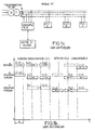
- This process ensuring a wave transmission of the various management messages, as shown in an illustrative manner in FIG. 1b, thus makes it possible to reach any ICC circuit, whatever the position thereof on the LV network.
- the repetition credit is for example brought to zero when the determined address management message has reached the ICC circuit of corresponding specified address, and the initial repetition credit allocated by the hub is chosen according to the hardware configuration of the network. BT and specific security criteria authorizing the repetition by the concentrator of the management message endowed with its repetition credit.
- the bit rate of the transmitted data is 300 bits / second.
- Such a transmission rate allows the data frames carrying these messages to be calibrated temporally on the LV network frequency, 50 Hz, regardless of the phase conductor to which an ICC circuit is connected.
- the transmission mode is of the bidirectional alternating type with transmission to the alternating of a carrier at 61 kHz, respectively 74 kHz each representative of the binary value 0 and 1 respectively. It follows that during a repetition, all the bits are transmitted synchronously. The carriers 61 and 74 kHz cannot, however, be synchronized. The initiative for the exchange is currently due to the concentrator alone.
- the response of the destination ICC circuit benefits, in the same way as the concentrator call - ICC circuit, from repetition with the same repetition credit value.
- the duration of a management message exchange between the concentrator and a given ICC circuit is of the order of 10 to 12 seconds.
- CPL-BT signals For a more detailed description of the characteristics of carrier current signals, CPL-BT signals, reference may usefully be made to European standard EN 50065-1. With reference to the aforementioned standard, it is simply indicated that the type of modulation used for low frequency carriers at 61 kHz and 74 kHz is SFSK modulation, for Spread Frequency Shift Keying , this type of modulation can be understood as a modulation mode FSK whose spectral lines are sufficiently distant from each other to avoid that the disturbance of one by a noise or parasite can practically reach the other. In such a case, the receiver treats the undisturbed line as if it were a simple transmission in OOK mode for ON-OFF KEYING , in English language.
- a logic is represented by the presence of the low frequency carrier at 61 kHz and the absence of the low frequency carrier at 74 kHz, and a logic zero by the absence of the low frequency carrier at 61 kHz and the presence of the low frequency carrier at 74 kHz.
- Document US-A-4 749 992 describes a device in which the PLC / radio frequency and PLC radio frequency channels include a common computer, which delivers digital data to modulate a radio frequency transmitter 42, for RF transmission, and an FM modulator 44 as well as a transmission oscillator 46 for the CPL transmission.
- An RF receiver 38 makes it possible to acquire the data by a computer 40, via a demodulator system 54 and a detector 56 which delivers digital PLC information.
- This device appears complex in that it has two separate parallel channels in the absence of common intermediate frequencies.
- the object of the present invention is to remedy the disadvantages mentioned above by the use of a device for interfacing a common bidirectional link low voltage CPL-BT / radio frequency carriers between a low voltage electrical power distribution line, allowing the transmission of signals by carrier currents, and radio space so as to allow extension transmission of low network management messages voltage to one or more low voltage networks and the generalization and extension of services corresponding.
- Another object of the present invention is the implementation using a device for interfacing a link bidirectional CPL-BT / radio frequency allowing transmission synchronous data transmitted in the form of carrier currents from a first to a second LV network, separate or not from the first LV network.
- the device for interfacing a bidirectional link low voltage carrier currents CPL-BT / radio frequency between a low power distribution line voltage, allowing the transmission of current signals carriers, and the radio space, object of this invention, is remarkable in that it comprises a circuit CPL-BT coupling interconnected to the low voltage line and allowing to deliver, on reception, the first signals representative of information in reception of currents carriers, a first channel, low carrier currents voltage / radio frequency comprising at least first transformation circuits of the first representative signals information in reception of carrier currents in a first intermediate frequency signal modulated in amplitude by these first signals representative of the information on reception of these carrier currents and first frequency transposition circuits of the first intermediate frequency signal into a modulation signal radio frequency transmission.
- a coupling device and transmission-reception at the first transposition circuits in frequency is interconnected to the first circuits of transposition in frequency and receives, on the one hand, in emission, the radio frequency emission modulation signal to transmit a radio frequency signal representative of the information of the carrier currents, and, on the other hand, in reception, a radiofrequency signal of reception.
- a second channel, radio frequency / current low voltage carriers is interconnected to the transmission-reception coupling and includes at least second signal transposition circuits receiving radio frequency as a second frequency signal intermediate, of the same frequency as that of the first intermediate frequency signal, and second circuits transformation of the second intermediate frequency signal as second signals representing information in the emission of carrier currents.
- the second circuits of transformation are interconnected and deliver the second signals representative of information in transmission of carrier currents on the CPL-BT coupling circuit, for transmission of this information in the form of currents carriers on the low voltage line.
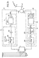
- the interfacing device object of the present invention includes a PLC-LV coupling module 1 interconnected to the LV low voltage line, this coupling module allowing deliver on reception of the first representative signals of information in reception of carrier currents propagating on the LV low voltage line.
- the first ones signals representative of information on reception of carrier currents are noted rcp in Figure 2a.
- the coupling module 1 CPL-BT is a commercially available coupling module such as the coupling module integrated into the circuits I.C.C previously mentioned in the description. At this As such, the coupling module 1 will not be described in detail.
- the interfacing device comprises a first channel, designated by low voltage / radio frequency carrier currents, this channel being denoted I in FIG. 2a and comprising at least a first module 10 for transforming the first signals representative of the information in reception rcp of the carrier currents into a first signal at intermediate frequency, denoted fi 1 in the above-mentioned figure.
- a first channel designated by low voltage / radio frequency carrier currents, this channel being denoted I in FIG. 2a and comprising at least a first module 10 for transforming the first signals representative of the information in reception rcp of the carrier currents into a first signal at intermediate frequency, denoted fi 1 in the above-mentioned figure.
- the first intermediate frequency signal fi 1 is amplitude modulated by the first signals representative of the information on reception of the carrier currents rcp.
- the first channel I also comprises a first module 11 for transposing in frequency the first intermediate frequency signal fi 1 into a radio frequency transmission modulation signal, noted sme in the aforementioned FIG. 2a.
- the first aforementioned channel I is also coupled to a radiofrequency coupling and transmission-reception device 2, this device 2 for coupling and transmission-reception being actually interconnected to the first frequency transposition module 11 in order to receive, on the one hand, in transmission, the modulation signal above-mentioned ems radio frequency emission issued by the first frequency transposition module 11, in order to perform thus the emission of a radiofrequency signal, denoted srfe, representative of information on carrier currents.
- a radio reception signal noted srfr, the representative radiofrequency signal, on the one hand, to the transmission of information on carrier currents and, on the other hand, when receiving reception information radio frequency, being, for the convenience of scoring, globally noted srf (e, r).
- the interfacing device, object of the present invention further includes, interconnected to device 2 of previously mentioned coupling and transmission-reception, a second channel, designated by radio frequency / current channel low voltage carriers, this second channel being denoted II and receiving the reception radio signal srfr previously mentioned.
- the second channel II comprises at least, as shown in FIG. 2a, a second module 20 for transposing the frequency of the radiofrequency reception signal srfr into a second signal at intermediate frequency, denoted fi 2 , this second signal at intermediate frequency having preferably the same frequency value as that of the first intermediate frequency signal fi 1 .
- the second channel II comprises a second module 21 for transforming the second intermediate frequency signal fi 2 into second signals representative of information in transmission of the carrier currents, these second signals being denoted ecp in FIG. 2a.
- the second transformation module 21 of the second intermediate frequency signal is interconnected to CPL-BT coupling module 1 to deliver to the latter the second signal representative of the information in transmission of the ecp carrier currents previously cited, in order to allow the transmission of this information in the form of carrier currents by the coupling module CPL-BT 1 on the LV low voltage line.
- CPL-BT coupling module 1 to deliver to the latter the second signal representative of the information in transmission of the ecp carrier currents previously cited, in order to allow the transmission of this information in the form of carrier currents by the coupling module CPL-BT 1 on the LV low voltage line.
- first module 10 of transformation of the first signals representative of the information received carrier currents
- first module 11 for transposition into frequency and the second channel II and its elements components
- second module 20 for transposition into frequency
- second module 21 for transforming the second intermediate frequency signal in second signals representative of information in transmission of carrier currents
- the CPL-BT 1 coupling module delivers the first signals representative of information in reception of rcp carrier currents at low alternation voltage in the form of a first, then a second signal low frequency of separate center frequency, i.e. signals at the frequency of 61 kHz and 74 kHz respectively, as previously mentioned in the description.
- the first module 10 for transforming the first signals representative of information in reception of currents rcp carriers can advantageously include a first 101 and a second 102 bandpass filter circuit of reception. These filter circuits are connected in parallel and each centered on the center frequency of the first and second low frequency signal respectively, that is to say on the frequency 61 kHz and 74 kHz.
- a circuit 103 for frequency transposition on reception is provided, this circuit 103 making it possible to deliver the first signal at intermediate frequency fi 1 .
- the frequency conversion circuit 103 on reception in fact delivers the first signal at wire intermediate frequency via an amplifier circuit 104 making it possible to adjust the level of the first signal to intermediate frequency fi 1 .
- the second module 21 for transforming the second intermediate frequency signal fi 2 advantageously comprises, in the embodiment shown in FIG. 2a, a circuit 211 for transposition into frequency in transmission, this transmission frequency transposition circuit being connected to the second frequency transposition module 20 of the reception radiofrequency signal srfr to thereby receive the second intermediate frequency signal fi 2 .
- the transmission frequency transposition circuit 211 thus delivers, from the second intermediate frequency signal fi 2 , a second transposed intermediate frequency signal, denoted tfi 2 in FIG. 2a.
- the frequency transposition circuit 211 in transmission receives the second intermediate frequency signal fi 2 by means of an amplifier 210, which of course makes it possible to analogously to the amplifier 104 of the first channel, to adjust the level of the second intermediate frequency signal fi 2 actually delivered to the frequency transposition circuit on transmission 211.
- the frequency transposition circuit on transmission 211 is itself followed, as shown in the Figure 2a, by a first 212 and a second 213 circuit emission bandpass filtering, these filtering circuits being connected in parallel analogously to filters 101 and 102 of the first channel and each centered on one respectively the other of the center frequencies of the first and the second low-frequency signal at 61 kHz and 74 kHz.
- the first 212 and second 213 bandpass filter circuit then deliver the second signals representative of information in emission of currents ecp carriers, these signals being centered on both of the aforementioned center frequencies and delivered to the CPL-BT 1 coupling via amplifier 214 for example.
- amplifiers such as amplifier 104, 210 and 214 have the function, on the one hand, of ensuring an adequate amplification of the transmitted signals and, on the other hand, to ensure decoupling and separation of different floors in accordance with classical notions in the frequency change technique.
- transposition circuit in reception frequency 103 and the transposition circuit in transmission frequency 211 it is indicated, according to a mode of particularly advantageous embodiment of the device interface object of the present invention, that these circuits each have a circuit for changing frequency 1030, respectively 2110, and that they comprise in addition to a common oscillator bearing the reference 4 on the Figure 2a.
- the first module 11 of frequency transposition of the first intermediate frequency signal fi 1 and the second module 20 for transposing into frequency the reception radiofrequency signal srfr previously mentioned in the description are designed and organized according to an architecture analogous to that of the modules 10 for transforming the first signals representative of the information on reception of the carrier currents and 21 of transformation of the second intermediate frequency signal fi 2 into second signals representative of information in transmission of the abovementioned carrier currents ecp.
- the first module 11 of frequency transposition of the first wire intermediate frequency signal into a radio frequency transmission modulation signal advantageously comprises a circuit 110 of transposition in frequency receiving the first signal at intermediate frequency fi 1 and delivering, for example by means of an amplifier 111, the signal for modulating radiofrequency emission sme previously cited in the description.
- the second module 20 for transposing the frequency of the radiofrequency reception signal srfr into a second intermediate frequency signal fi 2 advantageously comprises a circuit 201 for transposing frequency receiving the radiofrequency reception signal srfr via an amplifier 200 for example and delivering the second intermediate frequency signal fi 2 previously mentioned.
- the circuits of transposition in frequency 110 and 201 respectively comprise a frequency change circuit, carrying the reference 1110 respectively 2010 as well as an oscillator common room, bearing the reference 5, delivering the same frequency change signal at change circuits frequency proper 1110 and 2010.
- the coupling circuit 2 of the first channel I and the second channel II is interconnected to an antenna transmission-reception 3, which transmits, respectively receive, the transmit radio frequency signal and the reception radio signal signaled srf (er).
- the coupling circuit 2 can be implemented in the form of a so-called magic tee type circuit.
- the interfacing device that is the subject of the present invention thus makes it possible, thanks to a choice and an implementation of suitable frequency change, to transform the low frequency signals obtained by SFSK modulation on the CPL-BT carrier currents into signals in a UHF band at 433 MHz for example.
- the interfacing device as shown in Figure 2a is satisfactory.
- the choice and the implementation of common local oscillators 4 and 5, when the interfacing device object of the present invention includes two frequency change stages, both on the receiving channel, first channel, than on the sending channel, second track, provides stability in satisfactory frequency, while the switching time, that is to say the carrier establishment time in the direction of reception of PLC / emission carrier currents radio and current set-up time radio / PLC carriers, can be made much lower than the duration of a bit, that is to say 1/300 of a second.
- the time establishment time is around 250 ⁇ s.
- the interfacing device which is the subject of the present invention as described in FIG. 2a, it is indicated that this embodiment has been described with two stages of frequency change per channel, first channel and second channel, but that however, the number of stages of frequency change can be greater without in any way detracting from the nature of transparency sought with respect to the information transmitted.
- the number of frequency change stages is equal to two in each of the aforementioned first and second channels, it is indicated by way of nonlimiting example that when the radiofrequency signal of transmission or reception corresponds to a carrier frequency of 433 MHz, the common value for the first intermediate frequency signal fi 1 and the second intermediate frequency signal fi 2 can be taken equal to the above value 20.4 MHz.
- the second embodiment in accordance with the FIG. 2b, is now described in the case where the module of CPL-BT 1 coupling delivers the first representative signals information on reception of RCP carrier currents alternating low voltage in the form of a first, then of a second logic signal with two complemented values.
- the first signals representative of information in reception of RCP carrier currents actually correspond to 61 kHz low frequency signals and 74 kHz previously mentioned in the description, after detection for example and shaping to deliver the logic signals of aforementioned complemented values.
- the corresponding detection and shaping processing does will not be described in detail because it corresponds to a treatment of conventional type perfectly known to those skilled in the art.
- the first transformation module 10 comprises a circuit 105 generating a subcarrier wave , this circuit being constituted for example by a local oscillator delivering a subcarrier wave at 4 kHz for example, and an amplitude modulation circuit 106, receiving, on the one hand, the subcarrier wave delivered by the generator circuit 105 and, on the other hand, the first signals representative of the information on reception of the RCP carrier currents previously mentioned in the description.
- the amplitude modulator circuit 106 then delivers an amplitude modulated reception subcarrier wave, for example by means of an amplifier 104, this amplitude modulated reception subcarrier wave playing the role of the first frequency signal. intermediate FI 1 and therefore bearing the reference FI 1 .
- the second module 21 for transforming the second intermediate frequency signal FI 2 advantageously comprises an amplitude demodulator circuit 215 receiving the second intermediate frequency signal FI 2 , which corresponds to a subcarrier wave modulated in transmission amplitude , the demodulator circuit 215 delivering a demodulated sub-carrier wave in transmission amplitude, denoted DFI 2 .
- the amplitude demodulator circuit 215 is followed by a shaping circuit 216 receiving the demodulated subcarrier wave in DFI 2 transmission amplitude and delivering to the CPL-BT 1 coupling module the second signals representative of the carrier currents low voltage half-cycle, signals denoted ECP, in the form of a logic signal with two complemented values for re-transmission of the information received by radiofrequency in the form of carrier currents on the LV network.
- ECP the second signals representative of the carrier currents low voltage half-cycle
- first transposition module 11 in frequency and the second transposition module 20 in frequency of the first and second channel I, II it is indicated that these modules can be identical to those of the first embodiment shown in FIG. 2a and that as a result, the building blocks of these the latter bear the same reference.
- the amplitude modulated reception subcarrier FI 1 and the second intermediate frequency signal FI 2 have the same frequency value, i.e. 4 kHz, due to the structure of common local oscillator 5 on the first and second channels.
- the AM 215 demodulator can be constituted by any detection or clipping device constituting in fact a low-pass filter with cut-off frequency of the order of 2 kHz for example, which makes it possible to deliver a detected signal corresponding to the envelope of the second intermediate frequency signal FI 2 , this detected signal being none other than the constituent signal of the demodulated subcarrier wave in transmission amplitude DFI 2 .
- shaping circuit 216 from the demodulated subcarrier wave in DFI 2 transmission amplitude, can consist of a set of flip-flops having an absence of suitable rebound in order to ensure the transmission of the second signals representative of the carrier currents to the low-voltage alternating ECP in the form of the aforementioned logic signal with two complemented values.
- the first frequency transposition module 11 and the second frequency transposition module 20 can be replaced by a frequency modulation transmitter 110-E, respectively a frequency modulation receiver 201-R, the common local oscillator 5 being eliminated.
- the FM transmitter 110-E receives the IF signal 1 as a frequency modulation signal and the receiver 201-R delivers the IF signal 2 from FM reception.
- the presence of carrier currents on the network BT allows module 1 CPL-BT coupling to manage the transition from one to the other state on criteria of first appearance of one or the other signals.
- a detector circuit 12 of the first representative signals information on reception of rcp carrier currents, detector circuit 12 delivering a detection signal correspondent, designated by signal drcp.
- the second channel II comprises a circuit for detection 22 of the radio reception signal srfr.
- This detection circuit 22 delivers a detection signal correspondent, designated by signal dsrfr. Signals from dsrfr and drcp detection are then delivered to the management 6 previously mentioned.
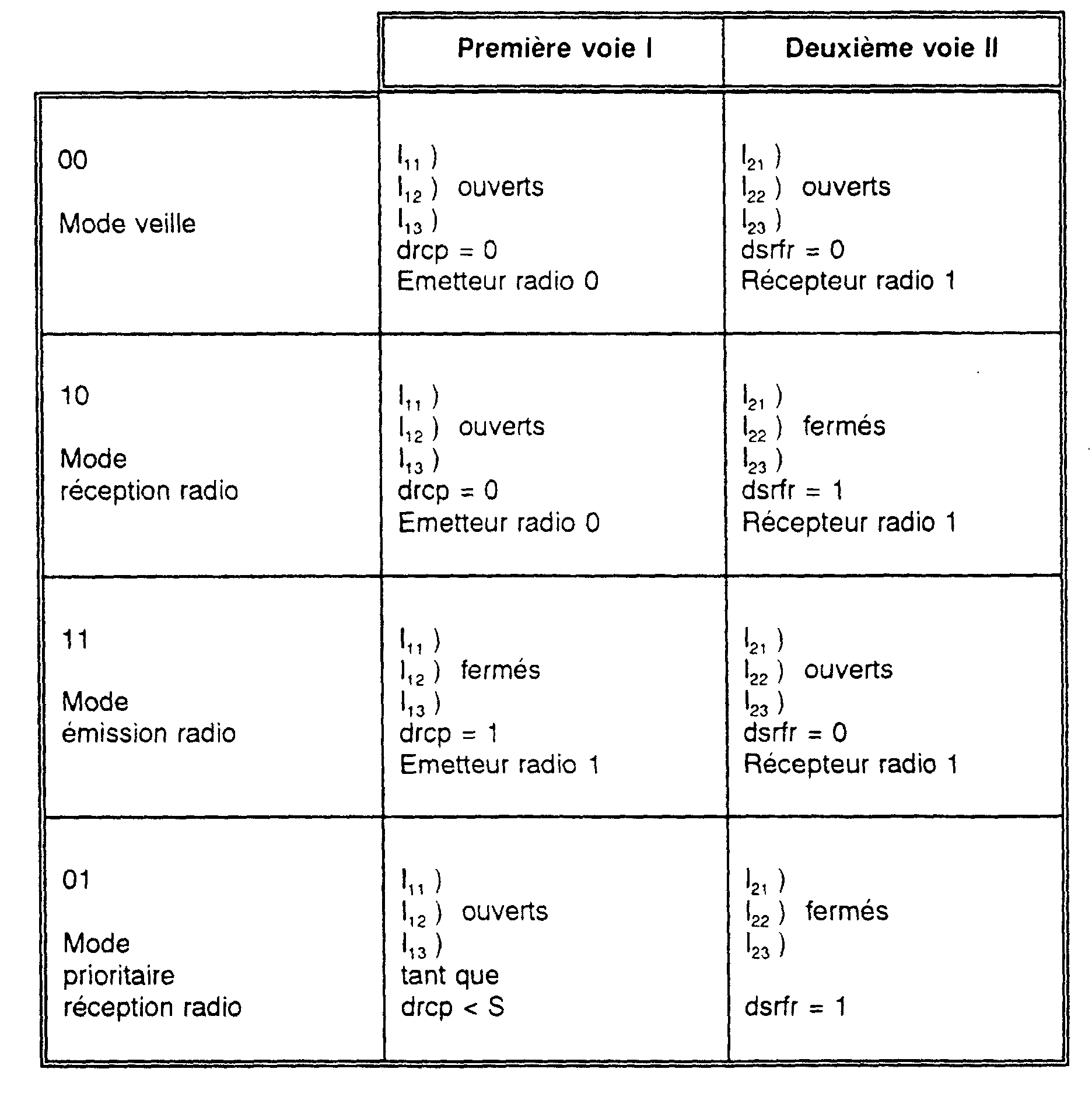
- command and control circuits for the first and second channels I, II can then be provided, these circuits being represented for the first channel I by switches I 11 , I 12 and I 13 , and for the second channel II, I 23 , I 22 and I 21 .
- the switches I 11 , I 21 can advantageously be mounted on the channel delivering the local oscillator signal delivered by the local oscillator 4 to the frequency change circuits 1030 respectively 2110
- the switches I 12 and I 22 can advantageously be mounted on the channels delivering the local oscillator signals from the local oscillator 5 to the frequency change circuits 1110, respectively 2010,
- switch circuits I 13 and I 23 can advantageously be mounted in switching mode in the first channel I at signal input transmission radiofrequency srfe at the coupling circuit 2, respectively at the output of the radiofrequency reception signal srfr of the coupling circuit 2. As shown in FIG.
- the switch I 13 can advantageously be controlled by switching between the output of amplifier 111, that is to say in fact the output of the first channel I, and the reference voltage d u device, while the switch I 23 can be controlled by switching between the input of the amplifier 200, that is to say the input of the second channel II and the reference voltage of the device.
- the aforementioned switches are represented in the form of electromechanical switches for understanding the corresponding functions, it is understood that these various switches can advantageously be produced by controlled electronic switches.
- the control of the aforementioned switches can then advantageously be carried out from the management module 6 to ensure the command and control of the first channel I and the second channel II respectively.
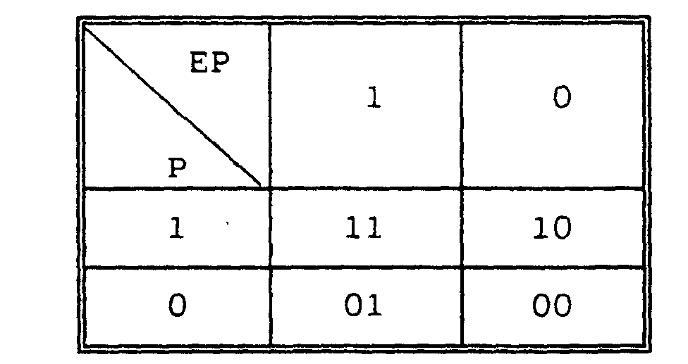
- the management module 6 can advantageously receive two binary variables, called programming or configuration variables, the variables EP, P respectively, capable of each occupying two binary values 0 or 1.
- the value 10 of combination of the variables EP and P corresponds to a radio reception mode for which it an srfr signal exists in the absence of signal reception carrier currents, the signal drcp being at the value 0.
- the state of the corresponding switches is given in the second truth table.
- the combination of the binary values EP and P at the value 11 corresponds to a transmission mode for a duration corresponding to at least one frame per radio broadcast, the signal drcp is equal to 1 and the switches of the first channel I are then closed to ensure the transmission function.
- the corresponding states of the second channel II are also given in the second truth table.
- the interfacing device which is the subject of the present invention, it can then be configured in a so-called priority mode in which radio reception is in fact preferred. , taking into account the difference in sensitivity thresholds between the radio receiver and the CPL-BT coupling module 1 to their respective signals.
- the signal drcp signal for detecting carrier currents in reception
- the switches I 11 , I 12 , I 13 of the first channel I then being kept open as long as the amplitude value of the signal drcp is less than this determined threshold value
- the switches I 21 , I 22 and I 23 then being kept closed and the signal dsrfr being maintained at the value 1 arbitrarily.
- the signals drcp and dsrfr can then be combined at the switching module 6 with the logic signals EP and P to deliver the control signals V1 and V2 symbolized by electromechanical commands in FIGS. 3a and 3b, to control the appropriate opening and / or closing of the switches I 11 , I 12 , I 13 of the first channel I, respectively I 21 , I 22 , I 23 of the second channel II.
- FIG. 4 a network has been shown. distribution system comprising an interconnected main network to a HV / LV substation fitted with a concentrator connected by a connection of the public switched telephone network PSTN to a management Center.
- the LV distribution network is pondered understand a main network made up of four branches directly interconnected to the HV / LV substation and for example three LV secondary networks, noted I, II and III, these secondary LV networks which may consist of isolated hamlets for example.
- these networks are not interconnected with the HV / LV substation equipped of the concentrator shown in Figure 4, but are at otherwise interconnected to other HV / LV stations no represented because they are not equipped with concentrators by definition.
- the branches of the main LV network each have a length around 1000 meters at most. They are equipped of a number of I.C.C circuits and the concentrator transmits data frames to these I.C.C circuits speed of 300 bits per second in alternation operation, as previously mentioned in the description.
- the lower branch of the main LV network is also provided an interfacing device in accordance with the subject of the present invention, this interfacing device being noted for convenience I.C.C-R-A and being of course provided with a bidirectional radio interfacing function.
- each interface device secondary LV networks is in direct vision of the device main network interface.
- each interfacing device can then be provided with an antenna Yagui type constituting the antenna 3 represented in the embodiments previously described. For a frequency of 433 MHz, the power of the transmitters radio allowing emission of the srfe signal does not exceed 0.1 watt.
- the transmit-receive antenna of the interfacing device I.C.C-R-A of the main LV network can on the contrary present qualities of omnidirectionality.
- the circuits I.C.C are represented by a hollow circle and the devices interfacing I.C.C-R-A, B, C, and D are shown by a circle with a cross.
- aforementioned interfacing devices, in accordance with the object of the present invention are mounted for example on a pole support for the conductors of the corresponding LV electrical network.
- Transmission of messages or data frames is carried out according to the process previously described by the description from the concentrator on the LV network main with wave repetition according to the process of emission credit previously described.
- object of the present invention Upon reaching by the aforementioned frames on the lower branch of the network Main LV of the I.C.C-R-A interfacing device, object of the present invention, it practically emits synchronism, i.e. at switching times near either channel, in the form of a radio message, the frame correspondent to the interfaces of secondary LV networks I.C.C-R-B-C, respectively D.
- the I.C.C interfaces represented by a blackened circle, main LV network receive correctly the aforementioned frame with a corresponding credit.
- the interfacing device in accordance with the subject of the present invention I.C.C-R-A Upon receipt of this frame, the interfacing device in accordance with the subject of the present invention I.C.C-R-A re-transmits at switching time near the tracks via radio broadcast, the corresponding messages or frames to devices of interfacing according to the invention arranged on LV networks secondary.
- the show is made with a repeat credit reduced to the value 1.
- FIG. 5e a chronogram of show and rehearsal with rehearsal credit from all of the aforementioned frames in the case of the network of LV distribution shown in Figures 4 and 5a to 5d.
- the interfacing device object of the present invention can be used to ensure the transmission in interactive mode on a distribution network low voltage electrical energy from a plurality of service management messages between a management center and a plurality of customer installations subscribed to these services when these facilities are simply interconnected to the low electrical power distribution network voltage.
- the interfacing device object of this invention has great flexibility of use, because it is sufficient to ensure the transmission of messages from management of the aforementioned services, whether the continuous branches or discontinuities of the electric power distribution network as illustrated in the previously mentioned figures, have at least one interfacing device according to the invention, each subscriber can simply be equipped an I.C.C interface previously mentioned in the description.
- each interfacing device according to the invention is in radio communication with another device for interfacing the same branch or a branch separate, and ensure the transmission of data and information conveyed by carrier currents low voltage CPL-BT in synchronism on each branch constitutive of the network.
- interfacing devices which are the subject of the present invention, it is indicated that these ensure a automated management of all subscribers living in hamlets isolated and to ensure a simplification of the management of the transmission of messages by carrier currents, in the measure where, for LV networks with high circuit density I.C.C, the implementation of several interfacing devices consistent with the object of the present invention allows lighten the wave transmission process on credit rehearsal.
- the implementation of the interfacing device, object of the present invention can be carried out in such a way as to make this device assimilable to a passive component for the network operator, a such a passive component requiring no intervention of the latter's share for long periods of operation.
Landscapes
- Engineering & Computer Science (AREA)
- Power Engineering (AREA)
- Computer Networks & Wireless Communication (AREA)
- Signal Processing (AREA)
- Mobile Radio Communication Systems (AREA)
- Transceivers (AREA)
Description
Ce dispositif concentrateur, lié par une liaison téléphonique par exemple avec un centre de gestion, permet d'envoyer sur le réseau BT des messages de gestion selon un processus de répétition avec crédit.
Les installations de chaque abonné intéressé par les services sont équipées d'un circuit d'Interface Clientèle Communicante, circuit I.C.C., branché entre l'un des conducteurs de phase et le neutre du réseau. Les messages de gestion, émis par exemple par le concentrateur, sur appel du centre de gestion, en un mode semi-interactif, se propagent, dans des conditions de réception correctes sur le réseau BT, sur une distance n'excédant pas 200 à 300 mètres environ.
Pour cette raison, le processus d'émission des messages de gestion consiste en un processus de répétition avec crédit de répétition, tout circuit I.C.C. recevant de l'amont, c'est-à-dire du commutateur lui-même ou d'un circuit I.C.C. amont, un message de gestion qui ne lui est pas destiné procédant à une décrémentation d'une unité du crédit de répétition puis à une réémission du message reçu, avec un crédit de répétition décrémenté. Ce processus, assurant une transmission par vagues des différents messages de gestion, tel que représenté de manière illustrative en figure 1b, permet ainsi d'atteindre tout circuit I.C.C., quelle que soit la position de celui-ci sur le réseau BT. Le crédit de répétition est par exemple porté à zéro lorsque le message de gestion d'adresse déterminée a atteint le circuit I.C.C. d'adresse spécifiée correspondante, et le crédit de répétition initial attribué par le concentrateur est choisi en fonction de la configuration matérielle du réseau BT et de critères spécifiques de sécurité autorisant la répétition par le concentrateur du message de gestion doté de son crédit de répétition.
Le mode de transmission est de type bidirectionnel à l'alternat avec émission à l'alternat d'une porteuse à 61 kHz, respectivement 74 kHz représentatives chacune de la valeur binaire 0 et 1 respectivement.
Il s'ensuit que lors d'une répétition, tous les bits sont émis de façon synchrone. Les porteuses 61 et 74 kHz ne peuvent toutefois pas être synchronisées. L'initiative de l'échange est due à l'heure actuelle au seul concentrateur. La réponse du circuit I.C.C. destinataire bénéficie, de la même manière que l'appel concentrateur - circuit I.C.C., de la répétition avec la même valeur de crédit de répétition. Pour des trames de données dont la durée est de l'ordre de la seconde et compte tenu d'un crédit de répétition initial de l'ordre de 3 ou 4, on peut estimer que la durée d'un échange de message de gestion entre le concentrateur et un circuit I.C.C. donné est de l'ordre de 10 à 12 secondes.
En référence à la norme précitée, on indique simplement que le type de modulation utilisé des porteuses basses fréquences à 61 kHz et 74 kHz est la modulation SFSK, pour Spread Frequency Shift Keying, ce type de modulation pouvant être compris comme un mode de modulation FSK dont les raies spectrales sont suffisamment distantes l'une de l'autre pour éviter que la perturbation de l'une par un bruit ou parasite ne puisse pratiquement atteindre l'autre. Dans un tel cas, le récepteur traite la raie non perturbée comme s'il s'agissait d'une simple transmission en mode O-O-K pour ON-OFF KEYING, en langage anglo-saxon.
Ainsi, un un logique est représenté par la présence de la porteuse basse fréquence à 61 kHz et l'absence de la porteuse basse fréquence à 74 kHz, et un zéro logique par l'absence de la porteuse basse fréquence à 61 kHz et la présence de la porteuse basse fréquence à 74 kHz.
Ce dispositif apparaít complexe dans la mesure où il dispose de deux voies parallèles distinctes en l'absence de fréquences intermédiaires communes.
- la figure 2a représente, sous forme d'un schéma fonctionnel, un dispositif d'interfaçage d'une liaison bidirectionnelle courants porteurs basse tension /radiofréquence, objet de l'invention, dans un premier mode de réalisation ;
- la figure 2b représente, sous forme d'un schéma fonctionnel, un dispositif d'interfaçage d'une liaison bidirectionnelle courants porteurs basse tension /radiofréquence, objet de la présente invention, dans un deuxième mode de réalisation ;
- la figure 2c représente une variante simplifiée du deuxième mode de réalisation représenté en figure 2b ;
- la figure 3a représente un dispositif d'interfaçage conforme au premier mode de réalisation représenté en figure 2a, dans une variante de réalisation dans laquelle ce dispositif est configurable ;
- la figure 3b représente un dispositif d'interfaçage conforme au deuxième mode de réalisation représenté en figure 2b, dans une variante de réalisation dans laquelle ce dispositif est également configurable ;
- la figure 4 représente, à titre illustratif, un réseau de distribution d'énergie électrique basse tension, comportant différentes tranches de réseaux de distribution de hameaux, équipés de dispositifs d'interfaçage conformes à l'objet de la présente invention ;
- les figures 5a à 5d représentent différents états du réseau représenté en figure 4 lors de la transmission successive, par vagues, de messages par crédit de répétition ;
- la figure 5e représente un chronogramme général des trames ou messages émis sur le réseau représenté en figure 4 au cours des étapes successives représentées en figures 5a à 5d.
Claims (9)
- Dispositif d'interfaçage d'une liaison bidirectionnelle courants porteurs basse tension CPL-BT / radiofréquence entre une ligne de distribution d'énergie électrique basse tension, permettant la transmission de signaux par courants porteurs, et l'espace radioélectrique, ce dispositif comportant des moyens (1) de couplage CPL-BT interconnectés à ladite ligne basse tension et permettant de délivrer, en réception, des premiers signaux (rcp) représentatifs d'une information en réception desdits courants porteurs et, en émission, lesdits courants porteurs pour transmission d'une information en émission desdits courants porteurs sur la ligne de basse tension, et un dispositif (2) de couplage et d'émission-réception radiofréquence, caractérisé en ce qu'il comporte :une première voie (I) courants porteurs basse tension/radiofréquence comportant au moins :ledit dispositif (2) de couplage et d'émission-réception radiofréquence étant interconnecté auxdits premiers moyens de transposition (11) en fréquence et recevant d'une part, en émission, ledit signal de modulation d'émission radiofréquence (sme) pour effectuer l'émission d'un signal radiofréquence représentatif de l'information en réception desdits courants porteurs, et, d'autre part, en réception, un signal radiofréquence de réception (srfr), ledit dispositif d'interfaçage comprenant en outre, interconnectée audit dispositif de couplage et d'émission-réception ;des premiers moyens (10) de transformation desdits premiers signaux (rcp) représentatifs de l'information en réception desdits courants porteurs en un premier signal à fréquence intermédiaire (fi1) modulé en amplitude par lesdits premiers signaux (rcp) représentatifs de l'information en réception desdits courants porteurs ;des premiers moyens (11) de transposition en fréquence dudit premier signal à fréquence intermédiaire en un signal de modulation d'émission radiofréquence (sme) ;une deuxième voie (II) radiofréquence /courants porteurs basse tension recevant ledit signal radiofréquence de réception (srfr) et comprenant au moins :des deuxièmes moyens (20) de transposition en fréquence dudit signal radiofréquence de réception (srfr) en un deuxième signal à fréquence intermédiaire (fi2) de même fréquence que celle du premier signal à fréquence intermédiaire (fi1) ;des deuxièmes moyens (21) de transformation du deuxième signal à fréquence intermédiaire (fi2) en deuxièmes signaux (ecp) représentatifs de ladite information en émission desdits courants porteurs, lesdits deuxièmes moyens (21) de transformation étant interconnectés et délivrant lesdits deuxièmes signaux (ecp) représentatifs de ladite information en émission desdits courants porteurs auxdits moyens (1) de couplage CPL-BT, pour transmission de cette information sous forme de courants porteurs sur la ligne basse tension.
- Dispositif selon la revendication 1, caractérisé en ce que lesdits moyens (1) de couplage CPL-BT délivrant lesdits premiers signaux (rcp) représentatifs de l'information en réception desdits courants porteurs à l'alternat basse tension sous forme d'un premier puis d'un deuxième signal basse fréquence de fréquence centrale distincte, lesdits premiers moyens (11) de transformation desdits premiers signaux (rcp) représentatifs de l'information en réception desdits courants porteurs comportent :un premier (101) et un deuxième (102) circuit de filtrage passe bande de réception, connectés en parallèle et centrés chacun sur la fréquence centrale du premier et du deuxième signal basse fréquence respectivement ;des moyens (103) de transposition en fréquence en réception connectés auxdits premier (101) et deuxième (102) circuit de filtrage passe bande de réception et délivrant ledit premier signal à fréquence intermédiaire (fi1) et en ce que lesdits deuxièmes moyens (21) de transformation du deuxième signal à fréquence intermédiaire (fi2) comportent :des moyens (211) de transposition en fréquence en émission, connectés auxdits deuxièmes moyens (20) de transposition en fréquence du signal radiofréquence de réception (srfr), recevant ledit deuxième signal à fréquence intermédiaire (fi2), et délivrant un deuxième signal à fréquence intermédiaire transposé,un premier (212) et un deuxième (213) circuit de filtrage passe-bande d'émission connectés en parallèle et centré chacun sur l'une respectivement l'autre fréquence centrale du premier respectivement du deuxième signal basse fréquence et délivrant lesdits deuxièmes signaux (ecp) représentatifs d'une information en émission desdits courants porteurs centrés sur l'une respectivement l'autre desdites fréquences centrales auxdits moyens (1) de couplage CPL-BT.
- Dispositif selon les revendications 1 et 2, caractérisé en ce que les moyens (20) de transposition en fréquence en réception, les moyens (11) de transposition en fréquence en émission, d'une part, et les premiers (10) et les deuxièmes (21) moyens de transposition en fréquence, d'autre part, comportent chacun :un circuit (110,2010) ; (1030,2110) de changement de fréquence, etun oscillateur (5,4) local commun.
- Dispositif selon la revendication 1, caractérisé en ce que lesdits moyens de couplage CPL-BT délivrant lesdits premiers signaux représentatifs de l'information en réception (RCP) desdits courants porteurs à l'alternat basse tension sous forme d'un signal logique à deux valeurs complémentées, lesdits premiers moyens (10) de transformation comportent :des moyens (105) générateurs d'une onde sous-porteuse,des moyens (106) de modulation en amplitude recevant, d'une part, ladite onde sous-porteuse, et, d'autre part, lesdits premiers signaux (RCP) représentatifs de l'information en réception desdits courants porteurs et délivrant une onde sous-porteuse de réception modulée en amplitude (FI1), jouant le rôle dudit premier signal à fréquence intermédiaire, et en ce que lesdits deuxièmes moyens (21) de transformation comportent :des moyens (215) démodulateurs d'amplitude recevant ledit deuxième signal à fréquence intermédiaire (FI2) correspondant à une onde sous porteuse modulée en amplitude d'émission et délivrant une onde sous-porteuse (DFI2) démodulée en amplitude d'émission ;un circuit de mise en forme (216) recevant l'onde sous-porteuse démodulée en amplitude d'émission et délivrant, auxdits moyens de couplage (1) CPL-BT, lesdits deuxièmes signaux représentatifs desdits courants porteurs à l'alternat basse tension sous forme d'un signal logique (ECP) à deux valeurs complémentées.
- Dispositif selon l'une des revendications 1 à 4, caractérisé en ce que celui-ci comporte en outre un module (6) de gestion de la première (I) et de la deuxième voie (II), ledit module (6) de gestion permettant d'assurer la commutation de l'une ou l'autre desdites voies, entre au moins un état de veille, un état de réception et un état d'émission radio.
- Dispositif selon la revendication 5, caractérisé en ce que ledit module (6) de gestion permet en outre d'assurer la commutation de l'une (I) ou l'autre voie (II) entre un état de veille et un état prioritaire d'émission, ce qui permet de programmer ledit dispositif parmi un ensemble de dispositifs en fonction de l'application considérée.
- Utilisation d'un dispositif selon l'une des revendications 1 à 6 pour assurer la transmission, en mode interactif, sur un réseau de distribution d'énergie électrique basse tension, d'une pluralité de messages de gestion de services entre un centre de gestion et une pluralité d'installations de clients abonnés à ces services, ces installations étant interconnectées au réseau de distribution d'énergie électrique basse tension.
- Utilisation selon la revendication 7, caractérisée en ce que le réseau de distribution d'énergie électrique basse tension étant subdivisé en branches continues ou discontinues, chaque branche comporte au moins un dispositif d'interfaçage selon l'une des revendications 1 à 6 en liaison radioélectrique avec un autre dispositif d'interfaçage de la même branche et/ou d'une branche distincte, deux dispositifs d'interfaçage (I.C.C) en liaison radioélectrique permettant d'assurer la transmission des données et informations véhiculées par lesdits courants porteurs basse tension CPL-BT en synchronisme sur chaque branche constitutive dudit réseau.
- Utilisation selon l'une des revendications 7 ou 8, caractérisée en ce que, pour une branche de réseau de distribution d'énergie électrique basse tension à haute densité d'installations d'abonnés, ladite branche comporte au moins deux dispositifs d'interfaçage en liaison radioélectrique, lesdits dispositifs d'interfaçage (I.C.C) constituant deux à deux un by-pass permettant d'assurer une transmission directe desdits messages de gestion.
Applications Claiming Priority (3)
| Application Number | Priority Date | Filing Date | Title |
|---|---|---|---|
| FR9612562A FR2754657B1 (fr) | 1996-10-15 | 1996-10-15 | Dispositif d'interfacage d'une liaison bidirectionnelle courants porteurs basse tension / radiofrequence |
| FR9612562 | 1996-10-15 | ||
| PCT/FR1997/001824 WO1998017013A1 (fr) | 1996-10-15 | 1997-10-13 | Dispositif d'interfaçage d'une liaison bidirectionnelle courants porteurs basse tension/radiofrequence |
Publications (2)
| Publication Number | Publication Date |
|---|---|
| EP0932943A1 EP0932943A1 (fr) | 1999-08-04 |
| EP0932943B1 true EP0932943B1 (fr) | 2001-07-18 |
Family
ID=9496676
Family Applications (1)
| Application Number | Title | Priority Date | Filing Date |
|---|---|---|---|
| EP97909397A Expired - Lifetime EP0932943B1 (fr) | 1996-10-15 | 1997-10-13 | Dispositif d'interfacage d'une liaison bidirectionnelle courants porteurs basse tension/radiofrequence |
Country Status (6)
| Country | Link |
|---|---|
| US (1) | US6069556A (fr) |
| EP (1) | EP0932943B1 (fr) |
| DE (1) | DE69705736T2 (fr) |
| ES (1) | ES2159120T3 (fr) |
| FR (1) | FR2754657B1 (fr) |
| WO (1) | WO1998017013A1 (fr) |
Families Citing this family (4)
| Publication number | Priority date | Publication date | Assignee | Title |
|---|---|---|---|---|
| FR2793582B1 (fr) * | 1999-05-12 | 2007-09-21 | Soule Materiel Electr | Dispositif de deport de signaux |
| FR2808149B1 (fr) | 2000-04-19 | 2003-01-31 | Electricite De France | Procede et dispositif de controle d'habilitation d'un appareil electrique connecte a un reseau |
| CN104597339B (zh) * | 2014-12-09 | 2019-06-07 | 国网安徽省电力公司淮南供电公司 | 具有语音装置的智能台区识别仪及识别方法 |
| CN106506047B (zh) * | 2016-12-20 | 2019-05-14 | 创达特(苏州)科技有限责任公司 | 一种低压电力线的载波通信方法、装置及系统 |
Family Cites Families (8)
| Publication number | Priority date | Publication date | Assignee | Title |
|---|---|---|---|---|
| US4556864A (en) * | 1982-08-26 | 1985-12-03 | Roy Joseph J | Apparatus and method for communicating digital information on AC power lines |
| US4589075A (en) * | 1983-02-23 | 1986-05-13 | Buennagel James A | Remote load data acquisition and control system for a power network |
| DE3320397A1 (de) * | 1983-06-06 | 1984-12-06 | Siemens AG, 1000 Berlin und 8000 München | Anordnung zur vermittelbaren uebertragung von tonsignalen |
| US4749992B1 (en) * | 1986-07-03 | 1996-06-11 | Total Energy Management Consul | Utility monitoring and control system |
| US4885564A (en) * | 1988-05-03 | 1989-12-05 | Thermo King Corporation | Power line carrier communication system for monitoring refrigerated containers |
| JPH0362631A (ja) * | 1989-07-31 | 1991-03-18 | Nissan Motor Co Ltd | コードレス電話の中継方式 |
| FR2684250B1 (fr) * | 1991-11-27 | 1994-04-01 | Merlin Gerin | Systeme de distribution d'energie electrique de haute qualite. |
| EP0714193A3 (fr) * | 1994-11-24 | 2000-11-22 | Marconi Communications Limited | Système de télécommunication amélioré via le réseau de distribution électrique |
-
1996
- 1996-10-15 FR FR9612562A patent/FR2754657B1/fr not_active Expired - Fee Related
-
1997
- 1997-10-13 WO PCT/FR1997/001824 patent/WO1998017013A1/fr not_active Ceased
- 1997-10-13 US US09/284,507 patent/US6069556A/en not_active Expired - Fee Related
- 1997-10-13 DE DE69705736T patent/DE69705736T2/de not_active Expired - Lifetime
- 1997-10-13 ES ES97909397T patent/ES2159120T3/es not_active Expired - Lifetime
- 1997-10-13 EP EP97909397A patent/EP0932943B1/fr not_active Expired - Lifetime
Also Published As
| Publication number | Publication date |
|---|---|
| US6069556A (en) | 2000-05-30 |
| EP0932943A1 (fr) | 1999-08-04 |
| WO1998017013A1 (fr) | 1998-04-23 |
| FR2754657B1 (fr) | 2002-12-27 |
| DE69705736T2 (de) | 2002-05-23 |
| ES2159120T3 (es) | 2001-09-16 |
| FR2754657A1 (fr) | 1998-04-17 |
| DE69705736D1 (de) | 2001-08-23 |
Similar Documents
| Publication | Publication Date | Title |
|---|---|---|
| EP0281440B1 (fr) | Dispositif pour la transmission à distance de signaux notamment de signaux vidéo | |
| EP0095959B1 (fr) | Système de radiocommunications, à sauts de fréquence | |
| EP0152341B1 (fr) | Procédé de télécommande d'équipements électriques et récepteur correspondant | |
| FR2713421A1 (fr) | Réseau local à transmission radio. | |
| EP0187067B1 (fr) | Système de commutation pour réseau de transmission numérique | |
| FR2459590A1 (fr) | Systeme combine de telediffusion et de transmission audiovisuelle | |
| FR2778802A1 (fr) | Dispositif d'emission et de reception d'ondes hyperfrequences polarisees circulairement | |
| EP0756389A1 (fr) | Circuit d'affectation d'un canal de transmission sur le réseau électrique | |
| EP0541406A1 (fr) | Procédé et dispositif pour la transmission de deux informations dans le cadre d'une liaison dite à étalement de spectre | |
| WO1998017013A1 (fr) | Dispositif d'interfaçage d'une liaison bidirectionnelle courants porteurs basse tension/radiofrequence | |
| EP0403339A1 (fr) | Base de transmission pour un dispositif de communication radio téléphonique | |
| FR2697699A1 (fr) | Dispositif de réamplification d'un signal radiofréquence, notamment pour des applications domestiques, et systèmes de réception correspondant. | |
| EP0755128A1 (fr) | Circuit de transmission de données binaires sur le réseau électrique utilisant plusieurs canaux de transmission | |
| EP0083895B1 (fr) | Circuit hyperfréquences remplissant les fonctions de modulateur, de mélangeur et de séparateur émission-réception et dispositifs utilisant un tel circuit | |
| EP1209823A1 (fr) | Procédé et système de télécommunication multimedia par satellites | |
| FR2721756A1 (fr) | Système d'antennes d'émission-réception omnidirectionnel à diversité angulaire et de polarisation. | |
| CA2164435C (fr) | Selection d'un satellite de rattachement | |
| EP0770286B1 (fr) | Procede et dispositif de transmission entre une pluralite d'unites locales connectees a differents reseaux de distribution de courant electrique | |
| FR2512300A1 (fr) | Systeme de transmission numerique a l'alternat a niveaux optimises | |
| FR2515400A1 (fr) | Installation de telesurveillance | |
| FR2680935A1 (fr) | Installation a reseau filaire de distribution de programmes audiovisuels et communication numerique a pont de donnees numeriques. | |
| EP0225269A1 (fr) | Modulateur par déplacement de phase MAQ 22n et, en particulier, modulateur MDP4 | |
| EP0876720A1 (fr) | Terminaux emetteurs/recepteurs utilisant un signal hertzien bidirectionnel a frequence porteuse unique pour les deux directions | |
| FR2752345A1 (fr) | Systeme de transmission par satellite presentant un canal de retour | |
| EP1400030A1 (fr) | Installation pour reseau de radiocommunication |
Legal Events
| Date | Code | Title | Description |
|---|---|---|---|
| PUAI | Public reference made under article 153(3) epc to a published international application that has entered the european phase |
Free format text: ORIGINAL CODE: 0009012 |
|
| 17P | Request for examination filed |
Effective date: 19990421 |
|
| AK | Designated contracting states |
Kind code of ref document: A1 Designated state(s): CH DE ES FR GB IE IT LI SE |
|
| 17Q | First examination report despatched |
Effective date: 19990806 |
|
| GRAG | Despatch of communication of intention to grant |
Free format text: ORIGINAL CODE: EPIDOS AGRA |
|
| GRAG | Despatch of communication of intention to grant |
Free format text: ORIGINAL CODE: EPIDOS AGRA |
|
| GRAH | Despatch of communication of intention to grant a patent |
Free format text: ORIGINAL CODE: EPIDOS IGRA |
|
| GRAG | Despatch of communication of intention to grant |
Free format text: ORIGINAL CODE: EPIDOS AGRA |
|
| GRAH | Despatch of communication of intention to grant a patent |
Free format text: ORIGINAL CODE: EPIDOS IGRA |
|
| GRAH | Despatch of communication of intention to grant a patent |
Free format text: ORIGINAL CODE: EPIDOS IGRA |
|
| GRAA | (expected) grant |
Free format text: ORIGINAL CODE: 0009210 |
|
| AK | Designated contracting states |
Kind code of ref document: B1 Designated state(s): CH DE ES FR GB IE IT LI SE |
|
| REG | Reference to a national code |
Ref country code: CH Ref legal event code: EP |
|
| REG | Reference to a national code |
Ref country code: IE Ref legal event code: FG4D Free format text: FRENCH |
|
| REF | Corresponds to: |
Ref document number: 69705736 Country of ref document: DE Date of ref document: 20010823 |
|
| REG | Reference to a national code |
Ref country code: CH Ref legal event code: NV Representative=s name: A. BRAUN, BRAUN, HERITIER, ESCHMANN AG PATENTANWAE |
|
| REG | Reference to a national code |
Ref country code: ES Ref legal event code: FG2A Ref document number: 2159120 Country of ref document: ES Kind code of ref document: T3 |
|
| GBT | Gb: translation of ep patent filed (gb section 77(6)(a)/1977) |
Effective date: 20010904 |
|
| ITF | It: translation for a ep patent filed | ||
| REG | Reference to a national code |
Ref country code: GB Ref legal event code: IF02 |
|
| PLBE | No opposition filed within time limit |
Free format text: ORIGINAL CODE: 0009261 |
|
| STAA | Information on the status of an ep patent application or granted ep patent |
Free format text: STATUS: NO OPPOSITION FILED WITHIN TIME LIMIT |
|
| 26N | No opposition filed | ||
| PGFP | Annual fee paid to national office [announced via postgrant information from national office to epo] |
Ref country code: SE Payment date: 20030917 Year of fee payment: 7 |
|
| PGFP | Annual fee paid to national office [announced via postgrant information from national office to epo] |
Ref country code: IE Payment date: 20030924 Year of fee payment: 7 |
|
| PGFP | Annual fee paid to national office [announced via postgrant information from national office to epo] |
Ref country code: CH Payment date: 20031013 Year of fee payment: 7 |
|
| PG25 | Lapsed in a contracting state [announced via postgrant information from national office to epo] |
Ref country code: IE Free format text: LAPSE BECAUSE OF NON-PAYMENT OF DUE FEES Effective date: 20041013 |
|
| PG25 | Lapsed in a contracting state [announced via postgrant information from national office to epo] |
Ref country code: SE Free format text: LAPSE BECAUSE OF NON-PAYMENT OF DUE FEES Effective date: 20041014 |
|
| PG25 | Lapsed in a contracting state [announced via postgrant information from national office to epo] |
Ref country code: LI Free format text: LAPSE BECAUSE OF NON-PAYMENT OF DUE FEES Effective date: 20041031 Ref country code: CH Free format text: LAPSE BECAUSE OF NON-PAYMENT OF DUE FEES Effective date: 20041031 |
|
| EUG | Se: european patent has lapsed | ||
| REG | Reference to a national code |
Ref country code: CH Ref legal event code: PL |
|
| REG | Reference to a national code |
Ref country code: IE Ref legal event code: MM4A |
|
| REG | Reference to a national code |
Ref country code: FR Ref legal event code: PLFP Year of fee payment: 19 |
|
| REG | Reference to a national code |
Ref country code: FR Ref legal event code: PLFP Year of fee payment: 20 |
|
| PGFP | Annual fee paid to national office [announced via postgrant information from national office to epo] |
Ref country code: GB Payment date: 20161014 Year of fee payment: 20 Ref country code: FR Payment date: 20161028 Year of fee payment: 20 Ref country code: DE Payment date: 20161013 Year of fee payment: 20 |
|
| PGFP | Annual fee paid to national office [announced via postgrant information from national office to epo] |
Ref country code: IT Payment date: 20161011 Year of fee payment: 20 Ref country code: ES Payment date: 20161027 Year of fee payment: 20 |
|
| REG | Reference to a national code |
Ref country code: DE Ref legal event code: R071 Ref document number: 69705736 Country of ref document: DE |
|
| REG | Reference to a national code |
Ref country code: GB Ref legal event code: PE20 Expiry date: 20171012 |
|
| PG25 | Lapsed in a contracting state [announced via postgrant information from national office to epo] |
Ref country code: GB Free format text: LAPSE BECAUSE OF EXPIRATION OF PROTECTION Effective date: 20171012 |
|
| REG | Reference to a national code |
Ref country code: ES Ref legal event code: FD2A Effective date: 20180508 |
|
| PG25 | Lapsed in a contracting state [announced via postgrant information from national office to epo] |
Ref country code: ES Free format text: LAPSE BECAUSE OF EXPIRATION OF PROTECTION Effective date: 20171014 |