EP0933103A2 - Suspension de roue pour des planches de glisse - Google Patents
Suspension de roue pour des planches de glisse Download PDFInfo
- Publication number
- EP0933103A2 EP0933103A2 EP99100627A EP99100627A EP0933103A2 EP 0933103 A2 EP0933103 A2 EP 0933103A2 EP 99100627 A EP99100627 A EP 99100627A EP 99100627 A EP99100627 A EP 99100627A EP 0933103 A2 EP0933103 A2 EP 0933103A2
- Authority
- EP
- European Patent Office
- Prior art keywords
- wheel
- der
- suspension according
- die
- skid
- Prior art date
- Legal status (The legal status is an assumption and is not a legal conclusion. Google has not performed a legal analysis and makes no representation as to the accuracy of the status listed.)
- Granted
Links
- 239000000725 suspension Substances 0.000 title claims abstract description 166
- 239000005060 rubber Substances 0.000 claims abstract description 4
- 229910000639 Spring steel Inorganic materials 0.000 claims abstract 2
- 239000013013 elastic material Substances 0.000 claims abstract 2
- 229920005830 Polyurethane Foam Polymers 0.000 claims 1
- 229920001821 foam rubber Polymers 0.000 claims 1
- 239000011496 polyurethane foam Substances 0.000 claims 1
- 230000033001 locomotion Effects 0.000 abstract description 36
- 230000009471 action Effects 0.000 abstract description 9
- 229920001971 elastomer Polymers 0.000 abstract description 7
- 239000006260 foam Substances 0.000 abstract description 2
- 230000008901 benefit Effects 0.000 description 35
- 230000000694 effects Effects 0.000 description 18
- XLYOFNOQVPJJNP-UHFFFAOYSA-N water Chemical compound O XLYOFNOQVPJJNP-UHFFFAOYSA-N 0.000 description 18
- 238000010276 construction Methods 0.000 description 17
- 230000000750 progressive effect Effects 0.000 description 16
- 230000006835 compression Effects 0.000 description 12
- 238000007906 compression Methods 0.000 description 12
- 238000013461 design Methods 0.000 description 10
- 238000005096 rolling process Methods 0.000 description 10
- 230000001133 acceleration Effects 0.000 description 8
- 238000013016 damping Methods 0.000 description 8
- 230000008859 change Effects 0.000 description 6
- 238000006073 displacement reaction Methods 0.000 description 6
- 230000007246 mechanism Effects 0.000 description 6
- 238000000034 method Methods 0.000 description 5
- 210000002023 somite Anatomy 0.000 description 5
- 229910000831 Steel Inorganic materials 0.000 description 4
- 238000013459 approach Methods 0.000 description 4
- 230000005540 biological transmission Effects 0.000 description 4
- 239000000806 elastomer Substances 0.000 description 4
- 239000000463 material Substances 0.000 description 4
- 239000010959 steel Substances 0.000 description 4
- 238000004804 winding Methods 0.000 description 4
- 206010041953 Staring Diseases 0.000 description 3
- 239000006096 absorbing agent Substances 0.000 description 3
- 239000012530 fluid Substances 0.000 description 3
- 238000009434 installation Methods 0.000 description 3
- 210000002414 leg Anatomy 0.000 description 3
- 229910052751 metal Inorganic materials 0.000 description 3
- 239000002184 metal Substances 0.000 description 3
- 239000004033 plastic Substances 0.000 description 3
- 229920003023 plastic Polymers 0.000 description 3
- 230000036316 preload Effects 0.000 description 3
- 230000008569 process Effects 0.000 description 3
- 238000005086 pumping Methods 0.000 description 3
- 230000035939 shock Effects 0.000 description 3
- 239000003381 stabilizer Substances 0.000 description 3
- 230000001360 synchronised effect Effects 0.000 description 3
- 238000013519 translation Methods 0.000 description 3
- 244000089486 Phragmites australis subsp australis Species 0.000 description 2
- 208000012886 Vertigo Diseases 0.000 description 2
- 229910052782 aluminium Inorganic materials 0.000 description 2
- XAGFODPZIPBFFR-UHFFFAOYSA-N aluminium Chemical compound [Al] XAGFODPZIPBFFR-UHFFFAOYSA-N 0.000 description 2
- 238000006243 chemical reaction Methods 0.000 description 2
- 238000012937 correction Methods 0.000 description 2
- 238000007688 edging Methods 0.000 description 2
- 230000005484 gravity Effects 0.000 description 2
- 210000003127 knee Anatomy 0.000 description 2
- 230000007935 neutral effect Effects 0.000 description 2
- 229920002635 polyurethane Polymers 0.000 description 2
- 239000004814 polyurethane Substances 0.000 description 2
- 230000008092 positive effect Effects 0.000 description 2
- 238000005381 potential energy Methods 0.000 description 2
- 230000002787 reinforcement Effects 0.000 description 2
- 125000006850 spacer group Chemical group 0.000 description 2
- 239000004575 stone Substances 0.000 description 2
- 238000006467 substitution reaction Methods 0.000 description 2
- 240000000731 Fagus sylvatica Species 0.000 description 1
- 206010016173 Fall Diseases 0.000 description 1
- 241000270295 Serpentes Species 0.000 description 1
- 239000004809 Teflon Substances 0.000 description 1
- 229920006362 Teflon® Polymers 0.000 description 1
- 230000009286 beneficial effect Effects 0.000 description 1
- 239000000969 carrier Substances 0.000 description 1
- 239000002131 composite material Substances 0.000 description 1
- 150000001875 compounds Chemical class 0.000 description 1
- 230000007797 corrosion Effects 0.000 description 1
- 238000005260 corrosion Methods 0.000 description 1
- 230000008878 coupling Effects 0.000 description 1
- 238000010168 coupling process Methods 0.000 description 1
- 238000005859 coupling reaction Methods 0.000 description 1
- 230000001419 dependent effect Effects 0.000 description 1
- 230000000994 depressogenic effect Effects 0.000 description 1
- 230000009977 dual effect Effects 0.000 description 1
- 239000013536 elastomeric material Substances 0.000 description 1
- 238000005516 engineering process Methods 0.000 description 1
- 230000001771 impaired effect Effects 0.000 description 1
- 230000000977 initiatory effect Effects 0.000 description 1
- 239000000314 lubricant Substances 0.000 description 1
- 238000012986 modification Methods 0.000 description 1
- 230000004048 modification Effects 0.000 description 1
- JTJMJGYZQZDUJJ-UHFFFAOYSA-N phencyclidine Chemical compound C1CCCCN1C1(C=2C=CC=CC=2)CCCCC1 JTJMJGYZQZDUJJ-UHFFFAOYSA-N 0.000 description 1
- 229920000642 polymer Polymers 0.000 description 1
- 238000011084 recovery Methods 0.000 description 1
- 230000001020 rhythmical effect Effects 0.000 description 1
- 238000007789 sealing Methods 0.000 description 1
- 239000000126 substance Substances 0.000 description 1
- 230000009747 swallowing Effects 0.000 description 1
- 238000012546 transfer Methods 0.000 description 1
Images





Classifications
-
- A—HUMAN NECESSITIES
- A63—SPORTS; GAMES; AMUSEMENTS
- A63C—SKATES; SKIS; ROLLER SKATES; DESIGN OR LAYOUT OF COURTS, RINKS OR THE LIKE
- A63C17/00—Roller skates; Skate-boards
- A63C17/01—Skateboards
- A63C17/011—Skateboards with steering mechanisms
- A63C17/013—Skateboards with steering mechanisms with parallelograms, follow up wheels or direct steering action
-
- A—HUMAN NECESSITIES
- A63—SPORTS; GAMES; AMUSEMENTS
- A63C—SKATES; SKIS; ROLLER SKATES; DESIGN OR LAYOUT OF COURTS, RINKS OR THE LIKE
- A63C17/00—Roller skates; Skate-boards
- A63C17/0046—Roller skates; Skate-boards with shock absorption or suspension system
-
- A—HUMAN NECESSITIES
- A63—SPORTS; GAMES; AMUSEMENTS
- A63C—SKATES; SKIS; ROLLER SKATES; DESIGN OR LAYOUT OF COURTS, RINKS OR THE LIKE
- A63C17/00—Roller skates; Skate-boards
- A63C17/01—Skateboards
-
- A—HUMAN NECESSITIES
- A63—SPORTS; GAMES; AMUSEMENTS
- A63C—SKATES; SKIS; ROLLER SKATES; DESIGN OR LAYOUT OF COURTS, RINKS OR THE LIKE
- A63C17/00—Roller skates; Skate-boards
- A63C17/12—Roller skates; Skate-boards with driving mechanisms
-
- A—HUMAN NECESSITIES
- A63—SPORTS; GAMES; AMUSEMENTS
- A63C—SKATES; SKIS; ROLLER SKATES; DESIGN OR LAYOUT OF COURTS, RINKS OR THE LIKE
- A63C17/00—Roller skates; Skate-boards
- A63C17/26—Roller skates; Skate-boards with special auxiliary arrangements, e.g. illuminating, marking, or push-off devices
- A63C17/262—Roller skates; Skate-boards with special auxiliary arrangements, e.g. illuminating, marking, or push-off devices with foot bindings or supports therefor
-
- A—HUMAN NECESSITIES
- A63—SPORTS; GAMES; AMUSEMENTS
- A63C—SKATES; SKIS; ROLLER SKATES; DESIGN OR LAYOUT OF COURTS, RINKS OR THE LIKE
- A63C2203/00—Special features of skates, skis, roller-skates, snowboards and courts
- A63C2203/40—Runner or deck of boards articulated between both feet
Definitions
- the invention relates to a wheel suspension according to DE 44 26 337 C, which describes the wheel suspension of a preferably four-wheeled roller board, by shifting weight or by tilting the base towards the inside of the curve Side is steered.
- wheel suspension according to DE 44 26 337 C, which describes the wheel suspension of a preferably four-wheeled roller board, by shifting weight or by tilting the base towards the inside of the curve Side is steered.
- roller boards spinateboards, Beach surfers or similar
- torsion beam suspension which in Connection with a suspension opposite the rigid axle suspension for superior driving characteristics both on the road and off-road.
- the twist beam axle described in the cited patent is based on the the trailing arm independent wheel suspension known from motor vehicle construction, in which the handlebars are arranged substantially in the longitudinal direction of the vehicle and around one Transverse axis are rotatably mounted on the vehicle body (swivel joint).
- the handlebars as well as the wheels attached to their ends turn when they compress and rebound on a circular path around this transverse axis and always keep their initial camber angle relative to the build. Therefore, during straight-ahead driving the camber angle of the wheels relative to the road is also constant when cornering
- this property leads to the disadvantage in motor vehicles that the Body and thus also the wheels tilt outward on the bend and thereby the wheels with increasing lateral acceleration (i.e. with increasingly positive camber) Lose cornering power.
- a purely trailing arm independent wheel suspension is unsuitable for roller boards, because the handlebars not only their camber but also their Maintain a constant steering angle relative to the body.
- the handlebars In order to initiate a Cornering automatically the inclination of the body or the standing area in a steering angle is implemented is between the opposite trailing arms an axis requires a kinematic cross-link, the steering angle generated as soon as the handlebars compress and rebound in opposite directions (indication for Cornering).
- the trailing arms are close to yours Swivel joint each provided with a lever arm that is approximately perpendicular to Longitudinal axis of the handlebar is and at its end a connecting element to each opposite handlebars.
- the swivel joints must enable trailing arms to make such a steering lock be replaced by cardan or ball joints.
- These joints point in contrast to the swivel joint several degrees of freedom of rotation and thereby clear also the trailing arms - in addition to the rotational movement about the transverse axis - relative to Establish a second degree of freedom of rotation: The rotation about an approximately vertical Axis of rotation (steering axis). This is due to the kinematic cross-connection second degree of freedom, however, canceled again, i.e. the steering angle of the wheels stands in a fixed assignment to the angle of inclination of the body or the footprint.
- the length of the lever (the vertical distance) is of particular importance here between the connecting elements and the gimbal of the Trailing arm on the body) the length of the transverse composite (the horizontal distance of the two opposite lever arms from each other) and the handlebar length (Distance of the wheels from the gimbal):
- the main object of the present invention is therefore for very agile roller boards the wheel suspension while maintaining the essential kinematic properties further improve such that they have a lower height of the roller board and allows an extremely low standing position.
- At least one of the joints must be as The hinge remains, otherwise the wheel suspension has a degree of freedom relative to the body would have too much and e.g. when exposed to lateral forces could fold away.
- the "gimbal" suspension of the trailing arms the according to the main claim a characteristic feature of the present invention as is the parent application, means that the trailing arm in essentially around an approximately horizontal axis (for compression and rebound) and about an approximately vertical axis (for steering), but not about its own (approximately turn the longitudinal axis).
- the redundant degree of freedom can, however, be an alternative to such swivel joints can also be lifted by a third ball-jointed auxiliary link, which supports the wheel suspension on the side and the lateral forces on the body transmits (e.g. Fig. 14-16).
- a third ball-jointed auxiliary link which supports the wheel suspension on the side and the lateral forces on the body transmits (e.g. Fig. 14-16).
- such four-link chains are made from the flat four-link chain are derived and in which at least when driving straight the handlebars around move transverse horizontal axes of rotation, called “quasi-flat” four-link chains, to differentiate them from the "real" spatial four-link chains, at which the auxiliary handlebars partly rotate around vertical or oblique axes.
- the versatile kinematic and constructive properties of the four-link chain can not only be used to optimize installation space, they are also used to optimize driving behavior.
- the joints can be achieved, for example, that the structure at Initiation of cornering raises and lowers again at the exit of the curve, see above that the standboard is back in his solely by the weight of the driver horizontal straight position can be reset (so-called weight reset; In the case of roller boards, the steering reset is usually carried out by special Spring elements). 9 and 10, this becomes extreme advantageous effect explained in more detail.
- An additional aim of the invention is the transfer of the outstanding driving characteristics the wheel suspension according to the invention also on skid vehicles, such as they are used e.g. as ice surfers.
- skid vehicles such as they are used e.g. as ice surfers.
- DE patent 44 26 337 proposes the kinematic advantages of the torsion beam axles can also be used with such skid vehicles.
- the present invention is also intended for the optional use of runners for torsion beam axles based on four-link chains.
- the initial shape of the four-link chain (with four swivel or cardan or ball joints) is realized.
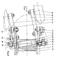
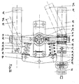
- the trailing arms 3 are each connected to the structure 4 via two auxiliary links 1 , 2 , which is screwed onto the stand board 11 and in this example consists of simple angle profiles.
- the handlebars On the front axle, left in Fig. 1, the handlebars are shown in normal position (straight ahead); on the rear axle each in a position that corresponds to extreme cornering: the inside left trailing arm 3 "' is drawn in the fully sprung position and the outside right trailing link 3"" in the fully sprung position.
- the lines of action of the two auxiliary links 1 , 2 enclose an angle a and intersect at the instantaneous pole M about which the longitudinal link 3 is currently rotating Lines of action on the inside of the (spring-loaded) pole Me and on the outside of the (spring-loaded) pole Ma.
- the momentary poles move on pole path P.
- part of the swivel joints must be designed as a cardan joint or ball joint in order to allow the longitudinal control arm to be steered by the angle ⁇ in plan view (FIG. 2).
- these are the joints 5 , 7 , 8 , while the joint 6 remains as a swivel joint in order to be able to support the torsional forces introduced by the wheel 10 and transmitted via the trailing arm 3 .
- the lateral support would be missing.
- the constructive design of the handlebars and joints as well as their mode of action are not dealt with here; they are largely identical to the components from the second exemplary embodiment (FIGS. 3-8) and are dealt with in more detail there.
- the kinematic cross-connection 9 is designed here as a swivel joint: on the trailing arms 3 , a shaft 15 'is pressed in on the left and a pipe 15 "is pressed in on the right, which surround one another concentrically and are supported one inside the other by the sliding bushes 16' and 16" .
- these also permit a displacement movement in the axial direction, which is necessary in order to avoid the trailing arms being squeezed when cornering.
- the steering angle ⁇ is greater, the further the connecting element 9 is in the vertical direction from the respective instantaneous pole by which the associated trailing arm rotates (and the smaller the longer the trailing arm and the longer the transverse connection).
- the vertical distance to the instantaneous pole can be varied as desired via the angle ⁇ of the two auxiliary links to one another, in the present exemplary embodiment it is far below the standing board (even below the roadway), although all of the links are arranged above. This illustrates the kinematic advantage over the parent registration.
- the cross-connection is moved in the other direction, i.e. away from the wheels, the opposite effect results, ie the wheels tilt even further towards the inside of the curve like the standing board.
- Similar kinematic variation options can be used if the auxiliary links, as in the second exemplary embodiment, are selected to be of different lengths.
- the wheel suspension also has a second degree of freedom that is used for the suspension.
- the main function of the suspension is to allow a relative movement between the body and the road (which in turn is made possible by the relative movements of the handlebars relative to the body) to cushion the bumps on the road surface and then to allow the body to move again as quickly as possible (i.e. without annoying reverberation, which is good damping assumes) to return to its normal position.
- lifting suspension it can also be used in the straight-ahead position or the assembly in the horizontal starting position. (Rolling is the side slope of the body when cornering in motor vehicle construction).
- the steering reset can either take place via separate suspension elements or - as in Fig. 1 - also be carried out by the lifting suspension.
- four tension springs 12 are selected as spring elements, which are suspended at the top of the trailing arms and at the bottom of the stand board in the spring element holders 13 , 14 and on which the stand board is "hanging". The springs are deflected every time you move your trailing arm in and out, making them effective for both steering and suspension movements (roll and lift suspension).
- the roller board from FIG. 1 is also equipped with foot straps 17 and a so-called mast foot 18 , with which a surf sail rig 20 (of which only the lower part of the mast is shown in broken lines in FIG. 1) can be attached to the stand board. So that the rig can be inclined to control and meter the wind power on all sides, it is connected to the mast base via a universal joint 19 (usually a rubber notch bearing). Since these are commercially available standard parts, they are not described in detail here.
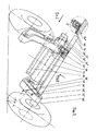
- a similar (quasi-flat) four-link chain is shown in a detailed version, but in contrast to Fig. 1, the spring forces are not via two tension springs per axis, but rather via a central compression spring (32 ) are supported on the body or standing board, and the handlebars are not arranged above, but below the standing board.
- the “first” auxiliary arm 21 (facing the wheel) is always under pressure and the “second” auxiliary arm 22 is always under tension.
- the distance between the trailing arm-side joints 25 , 26 is smaller than the distance between the body-side joints 27 , 28 .
- the "second" trailing arm-side joint ( 26 ) is designed as a swivel joint, while commercially available ball joints were chosen for the remaining 3 joints.
- the two joints 25 , 27 of the first auxiliary link 21 are pure ball joints (the steel ball heads rotate in plastic ball sockets, which are sealed by elastic sleeves and are mounted in steel housings);
- the gimbal joint 28 of the second auxiliary link is shown as an angle joint (swivel joint with a spherical sliding surface; does not allow angular deflections as large as pure ball joints).
- the angle joint 28 is screwed into the auxiliary link 22 and secured by the lock screw 39 .
- the rotary joint 26 is to reduce the component count, a structural unit with the storage of the connecting member 29, via the kinematic occurs the cross-laminated to the opposite trailing arms.
- the connecting element 29 is designed here as a separate tube which concentrically surrounds the tube pieces 35 ' , 35 " pressed into the cast aluminum longitudinal link 23' , 23" and is supported by the sliding bushes 36 thereon. (For example, commercially available Teflon bearings that do not require any lubricant can be used as sliding bushes).
- the pipe sections 35 ' , 35 "in turn comprise the shafts 38' , 38" of the rotary joints 26 via sliding bushes (37).
- the shafts 38 are pressed into the "second" auxiliary links 22 and connected to the angle joint 28 via them.
- This “double” swivel joint thus enables both the longitudinal links 23 to rotate relative to their auxiliary links 21 , 22 and also the longitudinal links to rotate relative to one another or to the connecting element 29 .
- the pairs of bushings 36 , 37 are each mounted at a large distance from one another in order to obtain the broadest possible support base for the forces and moments which are introduced by the wheels into the trailing arms.
- the material properties of the spring element can be changed (e.g. via the density of the Foam), there are numerous possible variations for fine-tuning suspension and damping behavior.
- a subsequent change in the suspension properties - e.g. adapting to different driver weights or changing the ground clearance - can be carried out simply by moving the spring element holder 34 on the underside of the standing board: either by moving the screwing points in the longitudinal direction or by a stepless adjustment mechanism as shown in Fig. 6 and 7 can be seen:
- the holder 34 has on its contact surface to the stand board on both sides an extension which engages in a recess in the body frame 24 and is clamped in when the body is screwed onto the underside of the stand board. To adjust the holder, it is sufficient to loosen the fastening screws and tighten them again after the adjustment.
- the holder - as shown in view X - could be fixed by a separate fastening rail 40 which is screwed onto the structure 24 .
- the connecting element 29 is in the normal position approximately perpendicular to the virtual rotary pole M.
- the connecting element forms a structural unit with the rotary bearing 26 , the associated auxiliary link must be used for this 22 in the normal position approximately vertically and the other auxiliary link 21 are correspondingly inclined in order to obtain a position of the instantaneous pole M exactly below the cross connection.
- the different lengths of the auxiliary links 21 and 22 have the result that the swivel joint 26 travels a greater distance when rebounding than when compressing, so that it is in a higher position ( 26 " ) on the outside of the bend than the standing surface 31 ( 26" ) than on the inside ( 26 ' ) and thus the connecting element 29 is slightly inclined in the front view (Fig. 7).
- This inclination by the angle b leads to the camber angle ⁇ of the wheels 30 increasing relative to the road by this angle ⁇ , that is to say the wheels are somewhat are more inclined towards the inside of the curve than the footprint 31.
- the "cornering effect” is thus increased. Depending on the requirements of the driving behavior, this effect can be compensated for or even increased by the fact that the kinematic cross-connection in the normal position is not exactly vertical above the Is arranged momentary pole, but something before or after it.
- the connecting element 29 has some axial play between the trailing arms 23 ' and 23 " in order to enable axial displacement of the trailing arms (in the transverse direction of the vehicle) to one another.
- the trailing arms are transverse in their transverse joints via their swivel joints 26' and 26 " and auxiliary links 22 ' and 22" are fixed to the body and therefore not only perform a rotational movement relative to each other during asynchronous compression and rebound, but also a slight displacement movement. Since the connecting tube is also rotatable with respect to the trailing arms (or their pipe sections 35 ' , 35 " ), it would assume an undefined position without the spring element 32 , against which it always rests and is fixed by friction.
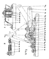
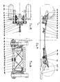
- FIG. 8 shows two exemplary embodiments of a four-bar chain, each with three rotary and one thrust joint: on the front axle, on the left in the picture, as a thrust crank mechanism (with the body-side joint 48 ' as a thrust joint) and on the rear axle as a crank loop (with the trailing arm-side joint 46 "' as a sliding joint).
- the thrust joint is realized on the front axle in the form of a rail 48 ' (slightly curved in the side view) in which - similar to the suspension of a sliding door - a small wheel 42' rolls, which is mounted on the trailing arm 43 ' by means of a swivel joint 46' and is led through the rail.
- the "first" auxiliary link 41 with its two ball joints 45 and 47 corresponds in principle to the auxiliary links 1 and 21 of the previous examples, while the function of the second auxiliary link as a transmission link between the thrust joint 48 'and the pivot joint 46' is taken over here by the wheel 42 '.
- a straight rail could also be used (then there would be a straight-thrust crank drive), but the curved path chosen here has the advantageous feature in some applications that the momentary pole during compression and rebound (shown in dashed lines) is less pronounced in the vertical direction moves and thus ensures a travel behavior that is more independent of the travel. If the rail were curved in the other direction, ie downwards at its ends, the pole track would be correspondingly steeper.
- the thrust crank drive has the advantage over the four-swivel chain that the swivel 46 'moves on a (almost) horizontal path and thus takes up only minimal vertical space.
- This configuration space advantage is fully exploited in the configuration of FIG. 8:
- the auxiliary link 41 ' is arranged in such a way that, when fully deflected - the most critical driving condition with regard to ground clearance - it almost bears against the underside of the standing board.
- Both the ball joint of the trailing arm 45e and its swivel joint 46'e are here in their highest vertical position, ie at the greatest possible distance from the road, so that an extremely low standing board position can be achieved.
- the fact that the auxiliary link moves away from the standing board when rebounding ( 45a ) is irrelevant to the ground clearance.
- the auxiliary link on the outside occupies a position (45'a) in which - like the large vertical distance of the (sprung) instantaneous pole Ma from the path of the swivel joint 46 'shows - a very strong sliding movement of the trailing arm in the horizontal direction and thus causes a large change in steering angle.
- a thrust joint in the form of a telescopic shock absorber (similar to the McPherson strut known from automotive engineering) is used, which is more complex than the front axle, but is more resistant to wear and corrosion.
- a piston rod 42 "' with attached piston 46"' slides in a hollow cylinder which forms a structural unit with the trailing arm 43 "' and displaces a hydraulic fluid (eg shock absorber oil) from a cylinder chamber when it springs in and out
- a hydraulic fluid eg shock absorber oil
- the other displaced hydraulic fluid flows through the valves 55 in the piston and opposes the piston movement a flow resistance (due to fluid friction), which dampens the vehicle vibrations and can be varied as desired via the adjustment of the valves, for example via the opening cross section of the Valves or the spring preload when using spring-loaded check valves.
- the piston rod 42 "'performs the function of the" second "auxiliary link, which by means of the ball joint 48 "'at the construction 44"' g is stored.
- Its trailing arm-side joint is the thrust joint, which is composed of the piston rod 42 "', the piston 46"' and the hollow cylinder.
- the first auxiliary link 43 "' with its ball joints 45"' and 47 “' as well as the connecting element 49"' (which is designed as a tube in FIG. 3-7, which comprises two shafts of the same diameter concentrically) are functionally identical to the corresponding ones Components of the front axle.
- the crank loop of the rear axle therefore has a kinematic behavior similar to that of the thrust crank drive of the front axle, but with a much steeper pole track; ie with an even more declining roll kinematics.
- FIG. 9 shows the wheel suspension from FIG. 8 in a top view, although some functional parts are varied compared to the side view: on the front axle, on the left in the picture, a functionally equivalent swivel joint 58 'is used instead of the wear-prone sliding joint 48'.
- a functionally equivalent swivel joint 58 ' is used instead of the wear-prone sliding joint 48'.
- the axis of the pivot joint 58 ' is approximately vertical and the associated (“second") auxiliary link 56' extends roughly across the direction of travel.
- the trailing arm-side joint 57 'of the auxiliary link 56' therefore moves in a top view on a circular path around the swivel joint 58 ', but describes an approximately horizontal straight line in the side view, so that there is a kinematic straight line in the projection onto the plane of the drawing.
- This variant therefore combines the practical advantages of the four-link chain (no wear-prone straight guide joints) with the kinematic advantages of the thrust crank mechanism (low vertical space requirement). It is one of the four-link chains because the axes of rotation of the two auxiliary links (41 'and 56') are not arranged parallel to each other.
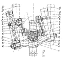
- a variant of the spatial four-link chain with a kinematic cross-connection (derived from the front axle suspension of FIG. 9) is carried out in detailed construction.
- an additional practical advantage is used, which results from the vertical axis of rotation of the "second" auxiliary link 62: the two auxiliary links are suspended here from a common pivot bearing 68 and rigidly connected to one another.
- This component is referred to below as a cross member 69 , into which a shaft 74 is cast and at the ends of which the longitudinal links 63 are guided on swivel joints 66 .
- the swivel joints 66 and 68 are each designed as double-row ball bearings 76 and 78 , the outer rings of which are pressed into the trailing arms 63 and the cross member 69, and the inner rings of which are pushed onto the shaft 80 and the screw of the swivel joint 68 and through the spacer tubes 75 and 77 are separated.
- the cross member 69 rigidly connects the left trailing arm 63 ' to the right 63 " and thus also advantageously takes over the function of the kinematic cross-connection. Since it is attached directly to the body by means of the swivel joint 68, it points with the rotation around this joint. in contrast to all the previous examples - but only a single degree of freedom relative to the body or the footprint.
- this degree of freedom of suspension consists in the fact that the kinematic cross-connection can also move in the longitudinal direction of the vehicle relative to the bodywork, thus allowing the two trailing arms to deflect or rebound synchronously) Rebound movements "of the trailing arms, but find them "Spring movements” no longer take place against the resistance of springs, but are kinematically dependent on one another via the cross-connection:
- the suspension is not only used for cost reasons, but mainly to fully exploit the kinematic advantages of the special shape of the torsion beam axle selected here.
- the (first) auxiliary link 61 is arranged "upside down", ie the body-side ball joint 67 is located below the trailing arm side ball joint 65 , as in FIG. 1, whereby the auxiliary link 61 is always subjected to tension .
- this arrangement has the advantage that the auxiliary link does not approach its extended position when it is deflected, but when it springs out, so that - as already mentioned - the body does not lower when the side is inclined, but rather rises ("support effect” or Progressive roll kinematics)
- This effect can also be seen from the fact that the spring deflection (height difference between 70NL and 70e) is significantly less than the spring deflection (difference between 70NL and 70a) of the driver, enables a completely new form of steering reset for roller boards: the weight reset.
- Twist-beam suspension offers and detailed in the master registration is received.
- the rigid axle roller board to call much better cornering power of the wheels through the inclination of the wheels with the base board is brought about in and out especially beneficial when "pumping" in fast change curves (higher speeds possible).
- This could increase this cornering effect be that the steering axis defined by the pivot 68 and thus also the path of the rotary joints 66 in the side view (Fig. 10) somewhat clockwise would be pivoted.
- the wheel suspension shows - although kinematically completely different - a certain similarity to a special form of rigid axle wheel suspension on, which is known from the published patent application 28 45 942.
- trailing arms (swing arms" 18, 20) rotatably suspended on which the wheels (26, 28) are mounted. These trailing arms are however so short that they have no significant influence on the steering and fall behavior of the wheels.
- Their function is only to: For the purpose of cushioning road impacts, a relative movement in vertical Allow direction between the cross member and the wheels; therefore they are via additional suspension elements (30, 82, 84, 116, 118, 176) with the cross member 16 connected.
- the steering function is performed solely by the cross member according to the usual Principle of rigid axle wheel suspensions for roller boards:
- the rigid axle or the Cross member is over a swivel bearing (pivot 44 with hole 36) hung on the underside of the stand board and is thus at a side inclination of the standing board forced to turn; the Resetting to the straight-ahead position takes place via a spring element ("buffer" 48).
- the size of the steering lock i.e. the assignment of steering angle and side inclination of the standing board, is determined by the angular position of the swivel joint 36/44.
- the axes of rotation must be inclined so that their lines of action cut below the standing board (otherwise the steering lock would be in the wrong direction).
- both turns are made against the resistance of independent spring elements: the steering movement against the buffer 48 (roll suspension) and the spring movement against the suspension elements, e.g. 30 (lifting suspension). Since both spring elements are connected in series and therefore can spring independently of each other, the suspension functions do not separate properly, i.e. the buffer 48 can also when springing respond and the suspension element when steering and vice versa. The result is an indifferent driving behavior influenced by many coincidences (e.g. vibration processes when driving over bumps where the axle beam 16 can swing back and forth between the springs 48 and 30). In the Master registration will address these disadvantages in detail.
- Helical compression springs as in Fig. 12/13 could also be arranged in an analogous arrangement in Fig. 11/12 are used to cushion the cross member 69 there against the structure 64. Since this cross member 69, however, without a longitudinal degree of freedom is rotatably attached to the structure, such springs would only be used for rotary movements of the cross member about its vertical axis of rotation and thus only serve to reset the steering (roll suspension). You would be in Fig. 10/11, however, only makes sense if there is the kinematic weight recovery effect was not sufficiently implemented or an additional steering provision would be desirable to e.g. the wheels already in during a jump attributed to the flight phase in the straight ahead position.
- FIGS. 14 to 16 is a wheel suspension in the form of a quasi-seven four-link chain, which is designed such that all the auxiliary links are always under tension and can therefore be designed as a rope like the auxiliary link 82 from FIGS. 12/13.
- the four-link chain is therefore kinematically a hybrid form from the first two exemplary embodiments (FIGS. 1-2 and 3-7).
- auxiliary links 101 and 102 it also has a third auxiliary link 115 , which supports the second (102) laterally and thus eliminates the use of a rotary joint in the four-link chain. All joints are therefore gimbal-type cable connections as with the auxiliary link from Fig. 12/13.
- auxiliary links on a vehicle axle consist of a single piece of rope. Its ends are thickened cylindrically and each is suspended in the first joint 107 on the body side . From there, in its function as the "first" auxiliary link 101, it leads to the first trailing arm-side joint 105 , which is designed as a fixed roller and is screwed to the trailing link 103. From this role it is stretched to the role of the second longitudinal-link joint 106 , which is screwed together with the connecting element 109 to the longitudinal link 103; see rear view (Fig. 16). From this picture it can be seen that the groove of the rollers serves to guide the rope in the articulation points.
- a roller segment or - as an additional kinematic variation option - a spiral guide as on the trailing arm 83 in Fig. 12 could be used.
- the configuration in Fig. 14 offers Roll as guide elements, because here the wrap angles of the rope are each well over 90 °).
- the fastening element 118 (only shown in FIGS. 14 and 15). By loosening this fastening element, the cable can be moved on the trailing arm and thus the length of the auxiliary links 101 and 102 can be varied in a simple manner.
- the rope now leads upwards from the second trailing arm-side joint 106 to the second body-side joint 108 ' and is fastened there on the stand board 111 with the aid of a clamp.
- This clamp is part of the superstructure 104 - a sheet metal construction which is pulled down from the second superstructure-side articulation point 108 to the first superstructure-side articulation point 106 and from there up to the front fastening screw on the stand board.
- the cable goes diagonally downwards from the second articulation point 108' to the center of the vehicle, is clamped there to the connecting element 109 by means of the clamp 116 and the pipe protection sleeve 117, and leads again diagonally upwards ( 115 " ) to the opposite articulation point 108 "on the body side .
- the two third auxiliary links 115 'and 115 support the connecting element 109 laterally in the manner of a truss and thus transmit the lateral forces introduced via the trailing arms to the body 104.
- the connecting element 109 is not designed as a (torsion-free) rotating or rotating thrust joint, but rather as a torsion-soft tube, as is known, for example, as a tube stabilizer from motor vehicle construction. To reduce the torsional rigidity, it can be partially or fully slotted.
- the tube 109 connects the two trailing arms 103 'and 103 "to one another in a flexurally stiff but torsionally soft manner and thus allows the two trailing arms to rotate relative to one another about the tube axis if the trailing arms deflect and deflect differently (cornering).
- This rotating movement is caused by the torsional stiffness of the pipe opposes a spring resistance, with which the connecting element 109 takes over the function of the roll suspension or the steering reset.
- the torsion spring rate can be varied via the pipe wall thickness and the length of the slot such that the entire roll suspension is applied by the pipe 109 alone Therefore, only one coil spring 112 is used here per vehicle axle, which engages in the center of the tube and therefore works exclusively as a lift spring, because it is not deflected in the same amount as asynchronous spring and rebound movements (pure cornering).
- Holder 113 is by means of the mounting bracket 116 is screwed to the tube 109, and the "body-side" spring plate 114 is attached directly to the underside of the stand board.
- the division of the lifting and rolling springs into two different spring elements has the advantage that the lifting and rolling spring rates can be adjusted independently of one another and subsequently changed independently of one another; Eg exchange of the coil spring to adapt to different driver weights or floor clearance requirements.
- tube 109 is twisted during asynchronous compression and rebound, twist the trailing arms are relative to each other - without axial displacement.
- the pipe 109 does not allow length compensation, which is why here strictly speaking, there is no kinematically exact suspension either. This in the present case, however, does not have a negative impact on driving behavior, since when cornering (if in FIG.
- the connecting element 109 is out of the drawing plane unscrewed and shortened in the projection to the drawing level) only one of the two "third" auxiliary links 115 'and 115 "due to lateral forces on the train is loaded and the other due to bulging of the rope - with simultaneous lifting of the connecting element - ensures the necessary length compensation.
- the wheel suspension according to the invention is used exclusively in four-wheel (or four-skid), two-axle and two-track vehicles which are controlled with both legs by means of inclined positions of the standing board.
- its main features in particular the wheels or runners inclined with the body when cornering - suggest that the torsion-beam axles also be paired with known axle designs of single-track vehicles (such as motorcycles or bicycles), the wheels of which are also placed in the curve.
- single-track vehicles such as motorcycles or bicycles
- the advantages of single-track vehicles can be combined with those of the two-track vehicle (including stability). 17 to 19 show two such exemplary embodiments.
- the exemplary embodiment from FIGS. 17/18 is also provided with a vehicle brake on the front axle.
- the braking torque is also transmitted here to the front wheels 124 'and 124 "via a V-belt drive.
- the V-belts 126' and 126" which are attached with their front ends to the brake pedal lever 128 and are suspended at the rear on the connecting element of the compound handlebar axle in normal driving a little bit down.
- the driver steps on the brake pedal lever 128, thereby tensioning both V-belts 126 'and 126 "against the pulleys 125' and 125" and thus generates a frictional force between the V-belt and the pulley or a braking torque on the front wheels.
- the brake could also be operated by hand using Bowden cables, and any other brake systems from the construction of bicycles, motorcycles or motor vehicles could also be used instead of the V-belt pulleys; such as disc, drum, rim or tire brakes.
- the torsion beam link 131 is used on the rear axle and combined with a single-track front axle 133 .
- the single-track axle 133 can be steered and is therefore similar to a bicycle, motorcycle or scooter front axle:
- the front wheel 134 is mounted in a fork 513 , which in turn is connected to the by means of an approximately vertical swivel 136
- Standboard 132 is connected and can be controlled by the driver using the handlebar 137 . Similar to a scooter, the driver stands on the stand board 132 and holds onto the handlebar 137.
- FIG. 20 shows another application of the wheel suspension according to the invention in combination with an articulated vehicle body.
- the standing area is divided into two in the manner of a so-called snakeboard, the two segments 142 ' and 142 "being connected to one another in an articulated manner via a connecting link 143.
- the swivel joints 144 twist the two segments towards each other in order to steer the vehicle in the desired direction of travel and to be able to move by rhythmic alternating cornering - in contrast to the original snakeboard, in which the unguided rigid axles do not allow the sides of the standing surfaces to tilt and the driver to one force an upright foot position, he can lie fully in the curve when using a torsion beam wheel suspension and actively use its self-steering behavior.
- the vehicle could be set in motion by the snakeboard-typical meandering movements and then moved on like a snowboard by tilting the standing board , I agree Both curve techniques can also be varied with each other as desired.
- Additional application 196 02 447.1-15 describes a constructive option how such an Ackermann geometry is realized with skid vehicles lets: In contrast to the wheels, which perform a "free" rotation when rolling, The runners only perform a narrowly limited rotation when they move in and out Rotate rebound in their bearings relative to the trailing arm.
- the skid axis of rotation therefore does not have to be at least approximately transverse-horizontal, like wheel rotation axes be arranged to the direction of travel, but can take any angle.
- This additional degree of freedom of the skid suspension compared to the Wheel suspension is used advantageously for generating an additional Steering effect used, which overlaps the steering angle of the torsion beam axis.
- both handlebars turn around their respective instantaneous poles and strike a steering angle; at the same time the runners turn in opposite directions Handlebar rotation back to their horizontal position and thereby generate an additional one Steering angle, provided the skid axis is not parallel to the kinematic Cross bond lie.
- the skid axes of rotation must be set at an angle so that somewhat reinforced by the additional steering effect of the inside steering angle and the outside of the curve is withdrawn somewhat, so that accordingly longer way, which the outside of the curve covers the inner skids, the curve radii are corrected and intersect at the curve center.
- Such boards can only be steered by rig control by moving the sail forward or backward is inclined. Because here the base board as well as the runners are inclined to There is almost no lateral acceleration possible to change the ice surface). Unless the ice is cleared after every snowfall, they are optimal Ice conditions - with a bare and flat ice surface - quite rare. Therefore recommends there is also the use of a suspension for ice surfers for universal applications, which costs a bit of height due to its travel requirements, but it does Even with bumpy or snow-covered ice for excellent driving characteristics worries.
- torsion beam axles according to the invention are used in the known Snake boards are used instead of their unguided rigid axles. Also there the typical snakeboard steering and locomotion (twisting both Legs to each other) thanks to the much more elegant snowboard curve technology (Body or hips with the base sloping inwards).
Landscapes
- Vehicle Body Suspensions (AREA)
Applications Claiming Priority (2)
| Application Number | Priority Date | Filing Date | Title |
|---|---|---|---|
| DE19803412 | 1998-01-29 | ||
| DE19803412A DE19803412A1 (de) | 1998-01-29 | 1998-01-29 | Radaufhängung für Rollbretter |
Publications (3)
| Publication Number | Publication Date |
|---|---|
| EP0933103A2 true EP0933103A2 (fr) | 1999-08-04 |
| EP0933103A3 EP0933103A3 (fr) | 2000-04-12 |
| EP0933103B1 EP0933103B1 (fr) | 2003-12-03 |
Family
ID=7856012
Family Applications (1)
| Application Number | Title | Priority Date | Filing Date |
|---|---|---|---|
| EP99100627A Expired - Lifetime EP0933103B1 (fr) | 1998-01-29 | 1999-01-14 | Suspension de roue pour des planches de glisse |
Country Status (2)
| Country | Link |
|---|---|
| EP (1) | EP0933103B1 (fr) |
| DE (2) | DE19803412A1 (fr) |
Cited By (13)
| Publication number | Priority date | Publication date | Assignee | Title |
|---|---|---|---|---|
| FR2823987A1 (fr) | 2001-04-27 | 2002-10-31 | Patrick Pierron | Chassis a deformation controlee pour un engin de glisse, notamment pour une planche a roulettes |
| WO2004011109A1 (fr) * | 2002-07-25 | 2004-02-05 | David Stratton | Planche a cerf-volant |
| WO2003095042A3 (fr) * | 2002-05-08 | 2004-03-18 | George Anthony Ltd | Planche de surf cerf-volant |
| WO2005025690A1 (fr) * | 2003-09-15 | 2005-03-24 | George French | Planche a roulettes tout-terrain |
| GB2426462A (en) * | 2005-05-25 | 2006-11-29 | Griffith Wilter | A steering mechanism for a snow board |
| US7967096B2 (en) | 2008-03-20 | 2011-06-28 | Zuumcraft, Inc. | Lean steering truck with a torsion spring assembly |
| EP3470319A1 (fr) * | 2017-10-11 | 2019-04-17 | 4 Traders GmbH | Rouleau à 3 roues à commande électrique |
| CN110052015A (zh) * | 2019-04-25 | 2019-07-26 | 林树森 | 一种可折叠电动滑板车 |
| US20210171132A1 (en) * | 2019-12-06 | 2021-06-10 | James Matthew Underwood | Stand up vehicle |
| CN113682751A (zh) * | 2021-08-11 | 2021-11-23 | 弥费实业(上海)有限公司 | 一种空中搬运装置及搬运系统 |
| WO2022024036A1 (fr) | 2020-07-30 | 2022-02-03 | Alcance Gradual, Lda | Planche à roulettes à suspension et direction indépendantes |
| US11325020B1 (en) | 2020-12-10 | 2022-05-10 | Milton, LLC | Electric skateboard |
| US12017135B2 (en) | 2021-06-24 | 2024-06-25 | Milton, LLC | Electric vehicle hub |
Families Citing this family (11)
| Publication number | Priority date | Publication date | Assignee | Title |
|---|---|---|---|---|
| DE10001719C2 (de) * | 2000-01-17 | 2002-03-07 | Marc Prager | Fahrgestell für Sportgeräte |
| DE20012267U1 (de) | 2000-07-15 | 2000-12-21 | Rohde, Holger, 53859 Niederkassel | Rollbrett |
| DE10047205A1 (de) * | 2000-09-23 | 2002-04-18 | Edmund Wagner | Körperkraftbetriebenes, lenkbares Fahrzeug zum Selbsttransport |
| DE10060663C1 (de) * | 2000-12-06 | 2002-01-31 | Wolfram Gorisch | Mehrspuriges, durch Neigung gelenktes Rollgerät |
| US6913272B2 (en) * | 2002-08-23 | 2005-07-05 | Chuck Chang | Skateboard having a three-dimensional independent suspension balance system |
| DE102004010051B4 (de) | 2004-03-02 | 2019-03-07 | Bayerische Motoren Werke Aktiengesellschaft | Durch Gewichtsverlagerung steuerbares Fahrgerät, insbesondere Schlitten |
| DE102004045464B3 (de) * | 2004-09-20 | 2006-03-09 | Chuck Chang | Skateboard-Radset mit einer Aufhängungsvorrichtung |
| DE102007031237B4 (de) | 2007-07-05 | 2009-05-07 | Gorisch, Wolfram, Dr. | Kippwinkel-gelenktes Rollgerät mit versetzten Rollen |
| WO2017035285A1 (fr) * | 2015-08-26 | 2017-03-02 | Prathamesh Manik Shinde | Planche à roulettes à mécanisme de direction multi-pivotant |
| US11406890B1 (en) | 2017-08-25 | 2022-08-09 | David Jackson | Skateboard assembly |
| DE102020204959B4 (de) | 2020-04-20 | 2022-03-17 | Volkswagen Aktiengesellschaft | Kraftfahrzeug |
Citations (3)
| Publication number | Priority date | Publication date | Assignee | Title |
|---|---|---|---|---|
| DE2845942A1 (de) | 1977-10-25 | 1979-06-13 | Robert D Johnson | Skateboard-fahrgestell |
| DE4426337C2 (de) | 1994-07-25 | 1997-01-09 | Rudi Mueller | Radaufhängung für Rollbrett |
| DE19602447A1 (de) | 1994-07-25 | 1997-07-31 | Rudi Mueller | Fahrwerke, insbesondere für Kufenfahrzeuge |
Family Cites Families (8)
| Publication number | Priority date | Publication date | Assignee | Title |
|---|---|---|---|---|
| DE2701761A1 (de) * | 1977-01-18 | 1978-07-20 | Albert Stuebbe Fa | Skate-board |
| DE2951893C2 (de) * | 1979-12-21 | 1983-01-05 | Adam Opel AG, 6090 Rüsselsheim | Bobschlitten |
| FR2638977B1 (fr) * | 1988-10-26 | 1991-10-11 | Battel Gerard | Engin autopropulse plus particulierement patins a roulettes motorises |
| FR2675703B1 (fr) * | 1991-04-24 | 1994-10-07 | Cartier Millon Guy | Skateboard. |
| US5263725A (en) * | 1992-02-24 | 1993-11-23 | Daniel Gesmer | Skateboard truck assembly |
| ES2072227B1 (es) * | 1992-04-09 | 1996-05-01 | John De Courcey Milne | Vehiculo deportivo |
| JP2993652B2 (ja) * | 1993-02-13 | 1999-12-20 | ユニテック 株式会社 | 電動遊戯具 |
| DE29518632U1 (de) * | 1995-11-24 | 1996-01-18 | Lin Liao, Yu-Ying, Feng Yuan | Skateboard |
-
1998
- 1998-01-29 DE DE19803412A patent/DE19803412A1/de not_active Withdrawn
-
1999
- 1999-01-14 EP EP99100627A patent/EP0933103B1/fr not_active Expired - Lifetime
- 1999-01-14 DE DE59907900T patent/DE59907900D1/de not_active Expired - Fee Related
Patent Citations (3)
| Publication number | Priority date | Publication date | Assignee | Title |
|---|---|---|---|---|
| DE2845942A1 (de) | 1977-10-25 | 1979-06-13 | Robert D Johnson | Skateboard-fahrgestell |
| DE4426337C2 (de) | 1994-07-25 | 1997-01-09 | Rudi Mueller | Radaufhängung für Rollbrett |
| DE19602447A1 (de) | 1994-07-25 | 1997-07-31 | Rudi Mueller | Fahrwerke, insbesondere für Kufenfahrzeuge |
Cited By (17)
| Publication number | Priority date | Publication date | Assignee | Title |
|---|---|---|---|---|
| FR2823987A1 (fr) | 2001-04-27 | 2002-10-31 | Patrick Pierron | Chassis a deformation controlee pour un engin de glisse, notamment pour une planche a roulettes |
| WO2003095042A3 (fr) * | 2002-05-08 | 2004-03-18 | George Anthony Ltd | Planche de surf cerf-volant |
| GB2404870A (en) * | 2002-05-08 | 2005-02-16 | George Anthony Ltd | Kiteboard |
| WO2004011109A1 (fr) * | 2002-07-25 | 2004-02-05 | David Stratton | Planche a cerf-volant |
| WO2005025690A1 (fr) * | 2003-09-15 | 2005-03-24 | George French | Planche a roulettes tout-terrain |
| GB2426462A (en) * | 2005-05-25 | 2006-11-29 | Griffith Wilter | A steering mechanism for a snow board |
| GB2426462B (en) * | 2005-05-25 | 2010-05-05 | Griffith Wilter | Snowboarding mechanisms |
| US7967096B2 (en) | 2008-03-20 | 2011-06-28 | Zuumcraft, Inc. | Lean steering truck with a torsion spring assembly |
| EP3470319A1 (fr) * | 2017-10-11 | 2019-04-17 | 4 Traders GmbH | Rouleau à 3 roues à commande électrique |
| CN110052015A (zh) * | 2019-04-25 | 2019-07-26 | 林树森 | 一种可折叠电动滑板车 |
| US20210171132A1 (en) * | 2019-12-06 | 2021-06-10 | James Matthew Underwood | Stand up vehicle |
| US11970223B2 (en) * | 2019-12-06 | 2024-04-30 | James Matthew Underwood | Stand up vehicle |
| WO2022024036A1 (fr) | 2020-07-30 | 2022-02-03 | Alcance Gradual, Lda | Planche à roulettes à suspension et direction indépendantes |
| US11325020B1 (en) | 2020-12-10 | 2022-05-10 | Milton, LLC | Electric skateboard |
| US12017135B2 (en) | 2021-06-24 | 2024-06-25 | Milton, LLC | Electric vehicle hub |
| CN113682751A (zh) * | 2021-08-11 | 2021-11-23 | 弥费实业(上海)有限公司 | 一种空中搬运装置及搬运系统 |
| CN113682751B (zh) * | 2021-08-11 | 2023-12-15 | 弥费实业(上海)有限公司 | 一种空中搬运装置及搬运系统 |
Also Published As
| Publication number | Publication date |
|---|---|
| EP0933103B1 (fr) | 2003-12-03 |
| EP0933103A3 (fr) | 2000-04-12 |
| DE19803412A1 (de) | 1999-08-05 |
| DE59907900D1 (de) | 2004-01-15 |
Similar Documents
| Publication | Publication Date | Title |
|---|---|---|
| EP0933103B1 (fr) | Suspension de roue pour des planches de glisse | |
| EP2086824B1 (fr) | Véhicule à trois roues | |
| DE69911372T2 (de) | Vorderradgabel- aufhängung für mountainbike und motorrad | |
| DE60025538T2 (de) | Vorrichtung für kippfahrzeug | |
| EP3099556B1 (fr) | Véhicule à cadre inclinable | |
| US4185847A (en) | Skateboard truck with independent wheel suspension | |
| DE10041046A1 (de) | Aufhängungssystem für Fahrzeuge | |
| DE4426337C2 (de) | Radaufhängung für Rollbrett | |
| DE102017001556A1 (de) | Fahrzeug mit Stabilisationselement | |
| DE102009042662A1 (de) | Achsmodul für Pendelachse eines Kraftfahrzeugs | |
| DE202016008844U1 (de) | "AFW"-Fahrzeugaufhängung (Varianten) | |
| WO2020164861A1 (fr) | Véhicule à châssis inclinable et système amortisseur à ressort | |
| DE102012107154B4 (de) | Fahrzeug | |
| DE102012003894A1 (de) | Vorderachsvorrichtung für ein mobil einsetzbares, insbesondere dreispuriges Fahrzeug, wie Trainingsgerät, Fahrrad oder Liegefahrrad, welches über einen zur Vorderachse verschwenkbaren Rahmen verfügt und welche durch eine Kopplungsvorrichtung an den Rahmen des Trainingsgerätes, Fahrrades oder Liegefahrrades koppelbar oder gekoppelt ist. | |
| EP2907734B1 (fr) | Suspension avant d'un véhicule | |
| DE102019109936A1 (de) | Frontgetriebenes Fahrzeug, insbesondere in Art eines Scooters | |
| DE19602447C2 (de) | Fahrwerke, insbesondere für Kufenfahrzeuge | |
| DE102006052041A1 (de) | Fahrzeug mit drei Rädern | |
| DE102017001557A1 (de) | Fahrzeug mit Ausgleichsgetriebe | |
| EP2032412B1 (fr) | Luge dirigeable équipée de deux patins | |
| DE102020003297A1 (de) | Dreirädriges Fahrzeug, insbesondere Lastendreirad | |
| DE102011106474A1 (de) | Straßenfahrzeug | |
| DE102019009125A1 (de) | Fahrzeug mit Neigerahmen und Lenkungssystem | |
| DE102004010051A1 (de) | Durch Gewichtsverlagerung steuerbares Fahrgerät, insbesondere Schlitten | |
| DE10256680A1 (de) | Einspuriges Rollsportgerät |
Legal Events
| Date | Code | Title | Description |
|---|---|---|---|
| PUAI | Public reference made under article 153(3) epc to a published international application that has entered the european phase |
Free format text: ORIGINAL CODE: 0009012 |
|
| AK | Designated contracting states |
Kind code of ref document: A2 Designated state(s): DE FR GB IT |
|
| AX | Request for extension of the european patent |
Free format text: AL;LT;LV;MK;RO;SI |
|
| PUAL | Search report despatched |
Free format text: ORIGINAL CODE: 0009013 |
|
| AK | Designated contracting states |
Kind code of ref document: A3 Designated state(s): AT BE CH CY DE DK ES FI FR GB GR IE IT LI LU MC NL PT SE |
|
| AX | Request for extension of the european patent |
Free format text: AL;LT;LV;MK;RO;SI |
|
| 17P | Request for examination filed |
Effective date: 20000427 |
|
| AKX | Designation fees paid |
Free format text: DE FR GB IT |
|
| GRAH | Despatch of communication of intention to grant a patent |
Free format text: ORIGINAL CODE: EPIDOS IGRA |
|
| GRAS | Grant fee paid |
Free format text: ORIGINAL CODE: EPIDOSNIGR3 |
|
| GRAA | (expected) grant |
Free format text: ORIGINAL CODE: 0009210 |
|
| AK | Designated contracting states |
Kind code of ref document: B1 Designated state(s): DE FR GB IT |
|
| REG | Reference to a national code |
Ref country code: GB Ref legal event code: FG4D Free format text: NOT ENGLISH |
|
| GBT | Gb: translation of ep patent filed (gb section 77(6)(a)/1977) |
Effective date: 20031203 |
|
| REF | Corresponds to: |
Ref document number: 59907900 Country of ref document: DE Date of ref document: 20040115 Kind code of ref document: P |
|
| ET | Fr: translation filed | ||
| PLBE | No opposition filed within time limit |
Free format text: ORIGINAL CODE: 0009261 |
|
| STAA | Information on the status of an ep patent application or granted ep patent |
Free format text: STATUS: NO OPPOSITION FILED WITHIN TIME LIMIT |
|
| 26N | No opposition filed |
Effective date: 20040906 |
|
| PGFP | Annual fee paid to national office [announced via postgrant information from national office to epo] |
Ref country code: DE Payment date: 20080228 Year of fee payment: 10 |
|
| PGFP | Annual fee paid to national office [announced via postgrant information from national office to epo] |
Ref country code: GB Payment date: 20090128 Year of fee payment: 11 |
|
| PGFP | Annual fee paid to national office [announced via postgrant information from national office to epo] |
Ref country code: IT Payment date: 20090129 Year of fee payment: 11 |
|
| PG25 | Lapsed in a contracting state [announced via postgrant information from national office to epo] |
Ref country code: DE Free format text: LAPSE BECAUSE OF NON-PAYMENT OF DUE FEES Effective date: 20090801 |
|
| PGFP | Annual fee paid to national office [announced via postgrant information from national office to epo] |
Ref country code: FR Payment date: 20090129 Year of fee payment: 11 |
|
| GBPC | Gb: european patent ceased through non-payment of renewal fee |
Effective date: 20100114 |
|
| REG | Reference to a national code |
Ref country code: FR Ref legal event code: ST Effective date: 20100930 |
|
| PG25 | Lapsed in a contracting state [announced via postgrant information from national office to epo] |
Ref country code: FR Free format text: LAPSE BECAUSE OF NON-PAYMENT OF DUE FEES Effective date: 20100201 |
|
| PG25 | Lapsed in a contracting state [announced via postgrant information from national office to epo] |
Ref country code: GB Free format text: LAPSE BECAUSE OF NON-PAYMENT OF DUE FEES Effective date: 20100114 |
|
| PG25 | Lapsed in a contracting state [announced via postgrant information from national office to epo] |
Ref country code: IT Free format text: LAPSE BECAUSE OF NON-PAYMENT OF DUE FEES Effective date: 20100114 |