EP0933113A1 - Appareil de separation - Google Patents
Appareil de separation Download PDFInfo
- Publication number
- EP0933113A1 EP0933113A1 EP98310112A EP98310112A EP0933113A1 EP 0933113 A1 EP0933113 A1 EP 0933113A1 EP 98310112 A EP98310112 A EP 98310112A EP 98310112 A EP98310112 A EP 98310112A EP 0933113 A1 EP0933113 A1 EP 0933113A1
- Authority
- EP
- European Patent Office
- Prior art keywords
- fluid
- inlet
- chamber
- outlet
- communicating
- Prior art date
- Legal status (The legal status is an assumption and is not a legal conclusion. Google has not performed a legal analysis and makes no representation as to the accuracy of the status listed.)
- Withdrawn
Links
- 238000000926 separation method Methods 0.000 title claims abstract description 12
- 239000012530 fluid Substances 0.000 claims abstract description 44
- 239000007787 solid Substances 0.000 claims abstract description 21
- XLYOFNOQVPJJNP-UHFFFAOYSA-N water Substances O XLYOFNOQVPJJNP-UHFFFAOYSA-N 0.000 claims abstract description 20
- 238000001914 filtration Methods 0.000 claims abstract description 7
- 230000000694 effects Effects 0.000 claims abstract description 6
- 239000006261 foam material Substances 0.000 claims description 2
- 239000006260 foam Substances 0.000 abstract description 2
- 239000000356 contaminant Substances 0.000 abstract 1
- 239000010419 fine particle Substances 0.000 abstract 1
- 239000002245 particle Substances 0.000 abstract 1
- 241000894006 Bacteria Species 0.000 description 2
- 239000003344 environmental pollutant Substances 0.000 description 2
- 230000005484 gravity Effects 0.000 description 2
- 231100000719 pollutant Toxicity 0.000 description 2
- 239000011435 rock Substances 0.000 description 2
- 238000004062 sedimentation Methods 0.000 description 2
- 239000011343 solid material Substances 0.000 description 2
- 241000251468 Actinopterygii Species 0.000 description 1
- 241000195493 Cryptophyta Species 0.000 description 1
- 238000004140 cleaning Methods 0.000 description 1
- 238000012423 maintenance Methods 0.000 description 1
- 239000011148 porous material Substances 0.000 description 1
- 230000008092 positive effect Effects 0.000 description 1
- 239000002893 slag Substances 0.000 description 1
- 239000002699 waste material Substances 0.000 description 1
Images
Classifications
-
- B—PERFORMING OPERATIONS; TRANSPORTING
- B04—CENTRIFUGAL APPARATUS OR MACHINES FOR CARRYING-OUT PHYSICAL OR CHEMICAL PROCESSES
- B04C—APPARATUS USING FREE VORTEX FLOW, e.g. CYCLONES
- B04C9/00—Combinations with other devices, e.g. fans, expansion chambers, diffusors, water locks
-
- B—PERFORMING OPERATIONS; TRANSPORTING
- B01—PHYSICAL OR CHEMICAL PROCESSES OR APPARATUS IN GENERAL
- B01D—SEPARATION
- B01D29/00—Filters with filtering elements stationary during filtration, e.g. pressure or suction filters, not covered by groups B01D24/00 - B01D27/00; Filtering elements therefor
- B01D29/01—Filters with filtering elements stationary during filtration, e.g. pressure or suction filters, not covered by groups B01D24/00 - B01D27/00; Filtering elements therefor with flat filtering elements
-
- B—PERFORMING OPERATIONS; TRANSPORTING
- B01—PHYSICAL OR CHEMICAL PROCESSES OR APPARATUS IN GENERAL
- B01D—SEPARATION
- B01D29/00—Filters with filtering elements stationary during filtration, e.g. pressure or suction filters, not covered by groups B01D24/00 - B01D27/00; Filtering elements therefor
- B01D29/88—Filters with filtering elements stationary during filtration, e.g. pressure or suction filters, not covered by groups B01D24/00 - B01D27/00; Filtering elements therefor having feed or discharge devices
- B01D29/90—Filters with filtering elements stationary during filtration, e.g. pressure or suction filters, not covered by groups B01D24/00 - B01D27/00; Filtering elements therefor having feed or discharge devices for feeding
- B01D29/908—Filters with filtering elements stationary during filtration, e.g. pressure or suction filters, not covered by groups B01D24/00 - B01D27/00; Filtering elements therefor having feed or discharge devices for feeding provoking a tangential stream
-
- B—PERFORMING OPERATIONS; TRANSPORTING
- B01—PHYSICAL OR CHEMICAL PROCESSES OR APPARATUS IN GENERAL
- B01D—SEPARATION
- B01D36/00—Filter circuits or combinations of filters with other separating devices
- B01D36/04—Combinations of filters with settling tanks
- B01D36/045—Combination of filters with centrifugal separation devices
-
- B—PERFORMING OPERATIONS; TRANSPORTING
- B04—CENTRIFUGAL APPARATUS OR MACHINES FOR CARRYING-OUT PHYSICAL OR CHEMICAL PROCESSES
- B04C—APPARATUS USING FREE VORTEX FLOW, e.g. CYCLONES
- B04C9/00—Combinations with other devices, e.g. fans, expansion chambers, diffusors, water locks
- B04C2009/004—Combinations with other devices, e.g. fans, expansion chambers, diffusors, water locks with internal filters, in the cyclone chamber or in the vortex finder
Definitions
- the present invention relates to apparatus for separating entrained solids from a fluid flow, and particularly, but not exclusively, to filtration apparatus for removing unwanted solid material from pond water.
- Pond filters are an almost essential part of any system designed to maintain pond hygiene, particularly with fishponds.
- pond filters work in two ways in order to clean the water thoroughly. On a purely mechanical level, they remove solid material including fish waste and algae, helping to create clear water. Secondly, on a biological level, they host "friendly" bacteria, particularly on the surfaces of the filter media, which remove harmful pollutants.
- apparatus for separating entrained solids from a fluid flow comprising a housing having a fluid inlet and a fluid outlet, with fluid flowing from the inlet to the outlet being swirled into a vortex to effect separation of entrained solid, characterised in that the housing comprises an inner chamber and an outer chamber, with one of the chambers communicating with the inlet and the other with the outlet, and with one of the chambers, in use, containing the vortex.
- the apparatus enables two different separation operations to be performed in a single housing.
- the other may be for further separation, possibly including filtration means such as brushes, porous materials e.g. foam or rock.
- filtration means such as brushes, porous materials e.g. foam or rock.
- the one chamber communicating with the inlet has a substantially circular cross-section.
- a circular section facilitates swirling of the fluid to create the vortex.
- the inlet directs fluid substantially tangentially to the curved periphery of the chamber communicating with it. Fluid entering the housing, either under gravity feed or the action of a pump, may have a significant velocity. By directing the fluid flow tangentially to the curved periphery, a cyclonic action may be generated automatically simply by harnessing the momentum of the flowing fluid.
- the inner periphery of the one chamber communicating with the inlet may taper towards a surface where separated solids will collect.
- the inner periphery may have a substantially conical, frusto-conical or paraboloid shape.
- the inlet is located nearer the separated-solids collection surface than the widest part of the tapered chamber.
- the apparatus may further comprise a weir disposed between the inner and outer chambers in order to control the flow of fluid therebetween.
- the level of the weir may be above the level of fluid in the inlet and may be above the level of fluid in the outlet. If the weir is at a higher level than the inlet and outlet, fluid must overflow from one chamber to the next in order to pass through the housing.
- the weir may make the passage of fluid through the housing more tortuous, which may increase sedimentation of entrained solid simply by slowing fluid flow.
- the outer chamber communicates with the inlet, and the inner chamber communicates with the outlet.
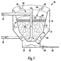
- FIG. 1 shows a schematic sectional view through a pond water treatment housing (10), which comprises inner chamber (12) and outer chamber (14).
- the inner and outer chambers are coaxial, with the inner chamber (12) surrounded around its radial periphery by the outer chamber (14).
- the outer chamber (14) receives pond water through inlet (16), either by gravity feed or through the positive action of a pump (not shown).
- the level of pond water received in outer chamber (14) rises until it overflows weirs (18) into the inner chamber (12).
- Pond water in the bottom of inner chamber (12) is drawn up through a tube (20) before leaving the housing through outlet (22).
- the course taken by the pond water through the housing (10) defines a tortuous fluid passageway, indicated in part by arrows (26).
- the lower part (30) of outer chamber (14) has a frusto-conical shape, and with the outer periphery of inner chamber (12) forms a section (31) of the fluid passageway (26).
- the inlet (16) directs fluid entering the section (31) substantially tangentially to its curved periphery.
- the curved periphery re-directs the fluid flow into a spiral path, as indicated by arrows "S".
- the spiralling motion of the water generates a vortex which is used to remove coarse solids entrained in the fluid.
- the coarse solids tend to gravitate down at the steep-sided section (30) towards apical discharge tray (32), whilst the water rises towards the weirs (18) .
- Solids (34) which have accumulated in tray (32) may be removed periodically through discharge pipe (36) by opening valve (38).
- the level of water in the inner chamber (12) is set by the level of outlet (22) which is below the level of the weirs (18).
- the water passes through screens (40) of resilient foam material to effect mechanical filtration.
- the filtered water then passes through a bed (42) of rock or the like, e.g. slag, which supports friendly bacteria to effect biological removal of pollutants in the water.
- Treated water collecting in the well (44) is drawn up through a tube (20) and returned to the pond through outlet (22).
Landscapes
- Chemical & Material Sciences (AREA)
- Chemical Kinetics & Catalysis (AREA)
- Cyclones (AREA)
Priority Applications (1)
| Application Number | Priority Date | Filing Date | Title |
|---|---|---|---|
| DE29824064U DE29824064U1 (de) | 1997-12-16 | 1998-12-10 | Separationsvorrichtung |
Applications Claiming Priority (2)
| Application Number | Priority Date | Filing Date | Title |
|---|---|---|---|
| GB9726514 | 1997-12-16 | ||
| GBGB9726514.4A GB9726514D0 (en) | 1997-12-16 | 1997-12-16 | Separation apparatus |
Publications (1)
| Publication Number | Publication Date |
|---|---|
| EP0933113A1 true EP0933113A1 (fr) | 1999-08-04 |
Family
ID=10823662
Family Applications (1)
| Application Number | Title | Priority Date | Filing Date |
|---|---|---|---|
| EP98310112A Withdrawn EP0933113A1 (fr) | 1997-12-16 | 1998-12-10 | Appareil de separation |
Country Status (2)
| Country | Link |
|---|---|
| EP (1) | EP0933113A1 (fr) |
| GB (1) | GB9726514D0 (fr) |
Cited By (3)
| Publication number | Priority date | Publication date | Assignee | Title |
|---|---|---|---|---|
| CN104307247A (zh) * | 2014-10-21 | 2015-01-28 | 胡建军 | 污水处理快速分离与循环过滤装置 |
| US9676638B2 (en) | 2012-06-15 | 2017-06-13 | 650438 Alberta Ltd. | Method and system for separation of suspensions |
| CN110743247A (zh) * | 2019-12-07 | 2020-02-04 | 新晃县污水处理有限责任公司 | 一种污水沉砂装置 |
Citations (6)
| Publication number | Priority date | Publication date | Assignee | Title |
|---|---|---|---|---|
| FR1104542A (fr) * | 1954-05-14 | 1955-11-21 | Procédé et appareils d'épuration de liquides | |
| GB1112309A (en) * | 1964-09-29 | 1968-05-01 | Max Berz | Improved process and apparatus for the separation of solid particles from fluids |
| US3594991A (en) * | 1964-09-29 | 1971-07-27 | Max Berz | Apparatus for separating suspended solid particles from a carrier gas |
| US4151091A (en) * | 1974-06-07 | 1979-04-24 | Societe Lab | Apparatus for separating solid pollutants from fluids |
| US4298465A (en) * | 1979-06-07 | 1981-11-03 | Racor Industries, Inc. | Fuel filter and water separator apparatus |
| WO1994028995A1 (fr) * | 1993-06-15 | 1994-12-22 | Jukka Kousa | Structure de filtre |
-
1997
- 1997-12-16 GB GBGB9726514.4A patent/GB9726514D0/en not_active Ceased
-
1998
- 1998-12-10 EP EP98310112A patent/EP0933113A1/fr not_active Withdrawn
Patent Citations (6)
| Publication number | Priority date | Publication date | Assignee | Title |
|---|---|---|---|---|
| FR1104542A (fr) * | 1954-05-14 | 1955-11-21 | Procédé et appareils d'épuration de liquides | |
| GB1112309A (en) * | 1964-09-29 | 1968-05-01 | Max Berz | Improved process and apparatus for the separation of solid particles from fluids |
| US3594991A (en) * | 1964-09-29 | 1971-07-27 | Max Berz | Apparatus for separating suspended solid particles from a carrier gas |
| US4151091A (en) * | 1974-06-07 | 1979-04-24 | Societe Lab | Apparatus for separating solid pollutants from fluids |
| US4298465A (en) * | 1979-06-07 | 1981-11-03 | Racor Industries, Inc. | Fuel filter and water separator apparatus |
| WO1994028995A1 (fr) * | 1993-06-15 | 1994-12-22 | Jukka Kousa | Structure de filtre |
Cited By (6)
| Publication number | Priority date | Publication date | Assignee | Title |
|---|---|---|---|---|
| US9676638B2 (en) | 2012-06-15 | 2017-06-13 | 650438 Alberta Ltd. | Method and system for separation of suspensions |
| US10464828B2 (en) | 2012-06-15 | 2019-11-05 | 650438 Alberta Ltd. | Method and system for separation of suspensions |
| US10906820B2 (en) | 2012-06-15 | 2021-02-02 | 650438 Alberta Ltd. | Method and system for separation of suspensions |
| CN104307247A (zh) * | 2014-10-21 | 2015-01-28 | 胡建军 | 污水处理快速分离与循环过滤装置 |
| CN104307247B (zh) * | 2014-10-21 | 2016-02-03 | 胡建军 | 污水处理快速分离与循环过滤装置 |
| CN110743247A (zh) * | 2019-12-07 | 2020-02-04 | 新晃县污水处理有限责任公司 | 一种污水沉砂装置 |
Also Published As
| Publication number | Publication date |
|---|---|
| GB9726514D0 (en) | 1998-02-11 |
Similar Documents
| Publication | Publication Date | Title |
|---|---|---|
| JP3920328B2 (ja) | 液体又は気体の流れから固形物を分離するための装置及びその方法 | |
| US6692645B1 (en) | Water reservoir filtration system and method | |
| CN1295156C (zh) | 从流动液体中分离和过滤颗粒以及生物体的设备和方法 | |
| EP0046070A2 (fr) | Séparateur | |
| US5866018A (en) | Vortex aquarium filter | |
| US3972816A (en) | Oil extractor | |
| CN215085508U (zh) | 一种用于污水处理污水与污泥分离的旋流分离装置 | |
| KR100380225B1 (ko) | 싸이클론식 연속여과기의 자동 역세 장치 | |
| CA2541998C (fr) | Collecteur de sable | |
| CN117580647A (zh) | 多旋风器沉积物过滤器 | |
| JP2009090268A (ja) | サイクロン式濾過装置 | |
| EP0128234B1 (fr) | Filtre à sable | |
| RU2006474C1 (ru) | Установка для очистки нефтесодержащих сточных вод | |
| KR200149548Y1 (ko) | 현탁물질 제거장치 | |
| US20240115976A1 (en) | Wastewater Treatment System | |
| RU54824U1 (ru) | Устройство для очистки нефтесодержащих сточных вод | |
| JP3973150B2 (ja) | スラッジ分離装置並びにスラッジ回収装置及びスラッジ分離方法 | |
| JP2547081Y2 (ja) | 処理液浄化装置 | |
| RU195743U1 (ru) | Безнапорный сепаратор для рыбоводных систем | |
| SU1230700A1 (ru) | Много русный гидроциклон | |
| SU887000A1 (ru) | Гидроциклон дл очистки сточной воды | |
| JP2004066149A (ja) | 移動床式ろ過装置のろ材再生装置 | |
| GB2480329A (en) | Filtering pond water | |
| CN208327569U (zh) | 一种新型污水净化器 | |
| SU1161189A1 (ru) | Установка дл очистки природных и сточных вод |
Legal Events
| Date | Code | Title | Description |
|---|---|---|---|
| PUAI | Public reference made under article 153(3) epc to a published international application that has entered the european phase |
Free format text: ORIGINAL CODE: 0009012 |
|
| AK | Designated contracting states |
Kind code of ref document: A1 Designated state(s): BE DE FR GB IT NL |
|
| AX | Request for extension of the european patent |
Free format text: AL;LT;LV;MK;RO;SI |
|
| 17P | Request for examination filed |
Effective date: 20000131 |
|
| AKX | Designation fees paid |
Free format text: AT BE CH CY DE DK LI |
|
| RBV | Designated contracting states (corrected) |
Designated state(s): BE DE FR GB IT NL |
|
| STAA | Information on the status of an ep patent application or granted ep patent |
Free format text: STATUS: THE APPLICATION HAS BEEN WITHDRAWN |
|
| 18W | Application withdrawn |
Withdrawal date: 20010201 |