EP0933134B1 - Maschine zur lackierung von leicht zu öffnenden deckeln - Google Patents
Maschine zur lackierung von leicht zu öffnenden deckeln Download PDFInfo
- Publication number
- EP0933134B1 EP0933134B1 EP97940164A EP97940164A EP0933134B1 EP 0933134 B1 EP0933134 B1 EP 0933134B1 EP 97940164 A EP97940164 A EP 97940164A EP 97940164 A EP97940164 A EP 97940164A EP 0933134 B1 EP0933134 B1 EP 0933134B1
- Authority
- EP
- European Patent Office
- Prior art keywords
- shaft
- revarnishing
- lids
- lid
- easy opening
- Prior art date
- Legal status (The legal status is an assumption and is not a legal conclusion. Google has not performed a legal analysis and makes no representation as to the accuracy of the status listed.)
- Expired - Lifetime
Links
Images


Classifications
-
- B—PERFORMING OPERATIONS; TRANSPORTING
- B05—SPRAYING OR ATOMISING IN GENERAL; APPLYING FLUENT MATERIALS TO SURFACES, IN GENERAL
- B05B—SPRAYING APPARATUS; ATOMISING APPARATUS; NOZZLES
- B05B7/00—Spraying apparatus for discharge of liquids or other fluent materials from two or more sources, e.g. of liquid and air, of powder and gas
-
- B—PERFORMING OPERATIONS; TRANSPORTING
- B05—SPRAYING OR ATOMISING IN GENERAL; APPLYING FLUENT MATERIALS TO SURFACES, IN GENERAL
- B05B—SPRAYING APPARATUS; ATOMISING APPARATUS; NOZZLES
- B05B13/00—Machines or plants for applying liquids or other fluent materials to surfaces of objects or other work by spraying, not covered by groups B05B1/00 - B05B11/00
- B05B13/02—Means for supporting work; Arrangement or mounting of spray heads; Adaptation or arrangement of means for feeding work
- B05B13/0221—Means for supporting work; Arrangement or mounting of spray heads; Adaptation or arrangement of means for feeding work characterised by the means for moving or conveying the objects or other work, e.g. conveyor belts
-
- B—PERFORMING OPERATIONS; TRANSPORTING
- B05—SPRAYING OR ATOMISING IN GENERAL; APPLYING FLUENT MATERIALS TO SURFACES, IN GENERAL
- B05B—SPRAYING APPARATUS; ATOMISING APPARATUS; NOZZLES
- B05B13/00—Machines or plants for applying liquids or other fluent materials to surfaces of objects or other work by spraying, not covered by groups B05B1/00 - B05B11/00
- B05B13/02—Means for supporting work; Arrangement or mounting of spray heads; Adaptation or arrangement of means for feeding work
- B05B13/04—Means for supporting work; Arrangement or mounting of spray heads; Adaptation or arrangement of means for feeding work the spray heads being moved during spraying operation
- B05B13/0421—Means for supporting work; Arrangement or mounting of spray heads; Adaptation or arrangement of means for feeding work the spray heads being moved during spraying operation with rotating spray heads
-
- B—PERFORMING OPERATIONS; TRANSPORTING
- B05—SPRAYING OR ATOMISING IN GENERAL; APPLYING FLUENT MATERIALS TO SURFACES, IN GENERAL
- B05C—APPARATUS FOR APPLYING FLUENT MATERIALS TO SURFACES, IN GENERAL
- B05C5/00—Apparatus in which liquid or other fluent material is projected, poured or allowed to flow on to the surface of the work
- B05C5/02—Apparatus in which liquid or other fluent material is projected, poured or allowed to flow on to the surface of the work the liquid or other fluent material being discharged through an outlet orifice by pressure, e.g. from an outlet device in contact or almost in contact, with the work
- B05C5/0208—Apparatus in which liquid or other fluent material is projected, poured or allowed to flow on to the surface of the work the liquid or other fluent material being discharged through an outlet orifice by pressure, e.g. from an outlet device in contact or almost in contact, with the work for applying liquid or other fluent material to separate articles
- B05C5/0212—Apparatus in which liquid or other fluent material is projected, poured or allowed to flow on to the surface of the work the liquid or other fluent material being discharged through an outlet orifice by pressure, e.g. from an outlet device in contact or almost in contact, with the work for applying liquid or other fluent material to separate articles only at particular parts of the articles
- B05C5/0216—Apparatus in which liquid or other fluent material is projected, poured or allowed to flow on to the surface of the work the liquid or other fluent material being discharged through an outlet orifice by pressure, e.g. from an outlet device in contact or almost in contact, with the work for applying liquid or other fluent material to separate articles only at particular parts of the articles by relative movement of article and outlet according to a predetermined path
-
- B—PERFORMING OPERATIONS; TRANSPORTING
- B21—MECHANICAL METAL-WORKING WITHOUT ESSENTIALLY REMOVING MATERIAL; PUNCHING METAL
- B21D—WORKING OR PROCESSING OF SHEET METAL OR METAL TUBES, RODS OR PROFILES WITHOUT ESSENTIALLY REMOVING MATERIAL; PUNCHING METAL
- B21D51/00—Making hollow objects
- B21D51/16—Making hollow objects characterised by the use of the objects
- B21D51/38—Making inlet or outlet arrangements of cans, tins, baths, bottles, or other vessels; Making can ends; Making closures
- B21D51/44—Making closures, e.g. caps
- B21D51/46—Placing sealings or sealing material
Definitions
- the invention proposed consists of a revarnishing machine for having an incision for easy opening lids, of the type using varnish projection nozzles and having a single or double revolving revarnishing head and a lid transporting device.
- the machine is provided with a single or double rotating motorised revarnishing head which applies varnish to the lids with a circular motion, with a conical varnish projection of adjustable height, by a revarnishing gun either with or without an additional separator of a thickness adjustable depending on the diameter of the lid to be varnished.
- the lid transporting device in the baseplate of the revarnisher is complemented by a drive chain at the base of the lid feeder which has an engine connected to a intermittent wheel race which provides four starts and four stops in each turn of the engine outlet shaft, the lids being varnished one at a time during the stops.
- object of the invention is a can feeder located in relation to the storage tower where the cans are gathered.
- Lid revarnishing machines are well known and widely used, the applicant having several patents related to devices incorporated to this type of machines (GB-A-2 269 122 and FR-A- 2 723 861).
- the present invention relates to a revarnishing machine for easy opening lids with a revolving revarnishing head, single or double, and a lid transporting device, as defined in independent claim 1.
- the head basically consists of a rotary slip driven by an above toothed pulley provided with a belt which connects with their pulleys, one of which is coupled to an electric drive motor from which the rotation is transmitted to the slip by said belt, and by a shaft fitted inside said slip; having a pneumatic revarnishing gun, with or without an additional separator which can be laterally adapted to the shaft, of a variable thickness depending on the size of the lid to be varnished, and conical bearings which absorb the axial and radial loads of the rotating head.
- the slip will revolve with the shaft, turning the gun included in a recess of the slip.
- the revarnisher is provided with a lid transportation device with an electric motor, connected by toothed pulleys and a belt to an intermittent gearing, starting and stopping, provided with two shafts, one at the inlet and one at the outlet, the first shaft revolving continuously, together with the motor, and the latter turning intermittently by a cam-follower mechanism which causes starts and stops to varnish the lids one at a time during the stops.
- a set of gears and a link chain also transmit the movement of the motor to a lid feeder.
- the lid feeder is located with relation to the lid storage tower, to place the lids on the transportation device.
- the lid feeder through a pair of helical gears placed on two perpendicular shafts, drives the shaft of a lid positioner and a discoidal dosing blade located above the positioner.
- the dosing blade has peripheral flaps to receive the outer edge of the lid and inclined peripheral flaps which make the lid descend after the blade turns, directing the lids towards the lid positioner located immediately below for their separation.
- the lid positioner has helical grooves which as they turn direct the outer edge of the lid towards the transporting device.
- the positioner shaft has a torque limiter associated to a spring which generates a signal received by a sensor when the positioner becomes blocked, causing the automatic stoppage of the machine.
- the transportation device moves the lids on conveyor belt with equidistant pull flaps and receives the intermittent motion, with starts and stops, of the intermittent gearing outlet shaft by a set of gears.
- the present invention relates to a revarnishing machine for easy opening lids, among the revarnishing machines which use varnish projection nozzles, characterised in that it is provided with a single or double revolving revarnishing head and a lid transportation device.
- the lid revarnishing revolving head is characterised in that it applies varnish to the lids on the circular incision of diameter between 52.5 and 99 mm.
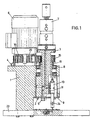
- the revolving head is mounted on a fixed support (1) to the revarnishing bench and to which is joined another circular support (4), on the upper part of which is an electric motor (6) to which is connected a toothed pulley (16) by a conical slip (20), with support (4) open in front to facilitate transmission by a toothed belt to the other pulleys.
- Toothed pulley (16) is engaged by a toothed belt (17) to a pulley (13) and to a tensor pulley (14) provided with bearings (22).
- Tensor pulley (14) is coupled to a conventional tensor (19) and attached to support (1) of the head by a shaft or a bolt, belt (17) also being engaged to pulley (15) which transmits the motion to a slip on which is a revolving shaft (3), slip (2) having an opening in its lower front area to house the pneumatic revarnishing gun (10), which is laterally connected to the lower end of shaft (3) with the interposition of an additional separator (11) of an adjustable size, depending on the diameter of the lid (12) to be varnished.
- Additional separator (11) moves gun (19) with respect to its rotation axis, being applicable preferably to types of lid (12) with diameters of 65.00, 73.15, 83.00, and 99.00 mm, or without separator (11) for lids of diameter 52.5 mm.
- Slip (2) is mounted on two conical roller bearings (8) which absorb all axial and radial loads produced during operation of the revolving head, roller bearings (8) being tightly fitted so that as slip (2) turns with respect to the inner race of the roller bearing, shaft (3) turns with it, so that the revarnishing gun (10) describes a circular motion.
- Gun (10) is provided with a thin nozzle (24) for applying the varnish to lid (12), with the varnish projection following a conical geometry, adjusting the height of gun (10) with respect to bench (23) between an upper and lower heights by a screw (5) inserted in a drill which is placed in the lower end of the shaft (3), so that when screw (5) is turned the shaft is displaced downwards with the consequent displacement of gun (10) while, in the opposite sense, gun (10) is separated with respect to the surface of baseplate (23).
- a screw (18) connects slip (2) to one of the conical roller bearings (8).
- a three stage revolving joint (7), coupled to the stop of the inner shaft of head (3) is provided with two orifices for inlet and return of varnish and another for air inlet for the pneumatic gun (10), this joint being formed by three bodies, two upper fixed bodies and a lower mobile body, which turns together with the inner shaft of head (3).
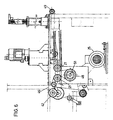
- the other device characteristic of this invention is the lid conveyor on the baseplate of the revarnisher, complemented by a drive chain to the lid feeder.
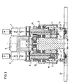
- a second electric motor (25) is coupled to a toothed pulley (26) which is connected by a toothed belt (27) to another pulley (28) located in the inlet axis of an intermittent gearing, which starts and stops, and which has two shafts (50), (51) located in opposite faces and at different heights, an inlet shaft (50) and an outlet shaft (51).
- Inlet shaft (50) turns continuously while outlet shaft (51) receives the motion made intermittent by a cam-follower device incorporated in gearing (29) so that in each revolution of the inlet shaft (50), outlet shaft (51) starts and stops once, turning 1 ⁇ 4 of a revolution, facilitating varnishing of the lids one at a time.
- gear (31) transmits the motion to the larger crown (34.1) while the crown with fewer teeth (34.2) connected to it turns, passing the motion through drive chain (35) to the lid feeder, to a single crown gear (36) located on the shaft of the feeder box (37).
- Feeder box (37) drives a shaft (38) connected to a lid positioner (39) and a dosing blade (40) placed on top, both in the shape of a disc, positioner (39) being provided with two helical channel grooves (52) located on its side at 180°, while blade (40) has a constant thickness along the surface, except in four sections, where there are peripheral flaps (53) of variable thickness.
- Flaps (53), two inlet and two outlet, of blade (40) collect and separate lids (12) from the feeding tower (41), inserting them below into one of the channel grooves (52) of positioner (39).
- lid positioner (39) and dosing blade (40) are received from a pair of helical contact gears placed on two perpendicular axes, on the feeder box shaft and on shaft (38).
- Shaft (38) is provided with a torque limiter (43) on which acts a spring (44), so that when positioner (43) is blocked limiter (43) moves from its natural position and an inductive sensor (45) which acts by proximity generates a signal and automatically stops the machine.
- a torque limiter (43) on which acts a spring (44), so that when positioner (43) is blocked limiter (43) moves from its natural position and an inductive sensor (45) which acts by proximity generates a signal and automatically stops the machine.
- the lid conveyor is located in the geometrical centre of lid (12) revarnishing baseplate (23) and moves these lids by a transporting link chain (46) placed on a central groove (46.1) which is provided with pull flaps (47) for lids (12) placed equidistant from each other along the drive and receiving an intermittent, start-stop motion in the outlet shaft (51) of the wheel race (29) by a double crown drive gear (48) complemented by two other gears (49) and (42) located on the ends of the conveyor, plus another two double crown gears (21) placed next to the drive gear (48), one of which acts as a tensor gear, the set of gears and conveyor chain (46) forming a loop around the outlet shaft (51) of intermittent gearing (29).
- a transporting link chain (46) placed on a central groove (46.1) which is provided with pull flaps (47) for lids (12) placed equidistant from each other along the drive and receiving an intermittent, start-stop motion in the outlet shaft (51) of the wheel race (29) by a double crown drive
Landscapes
- Engineering & Computer Science (AREA)
- Mechanical Engineering (AREA)
- Spray Control Apparatus (AREA)
- Coating Apparatus (AREA)
- Sealing Of Jars (AREA)
- Manufacture Of Motors, Generators (AREA)
- Details Or Accessories Of Spraying Plant Or Apparatus (AREA)
- Casting Or Compression Moulding Of Plastics Or The Like (AREA)
- Devices For Post-Treatments, Processing, Supply, Discharge, And Other Processes (AREA)
Claims (16)
- Überlackiermaschine für Deckel mit einem Einschnitt zum leichten Öffnen, wie sie bei Lackierprojektionsdüsen verwendet werden, ein einzelner oder doppelter Überlackierkopf und eine Vorrichtung zum Transport der Deckel, dadurch gekennzeichnet, dass sie über eine Überlackierpistole (10) verfügt, die abhängig von der Grösse des Deckels (12) einen unterschiedlich dicken, zusätzlichen Abscheider (11) hat und durch Rotieren des Drehkopfs den Lack mit kreisförmigen Bewegungen auf dem Durchmesser des Einschnitts und aus einem konischen, höhenverstellbaren Strahler auf den Deckel aufträgt. Ausserdem verfügt sie über eine Vorrichtung zum Transport der Deckel mit einem Motor (25), der an ein Aussetzzahnradgetriebe (29) angeschlossen ist, dessen Ausgangswelle (51) ein Förderband (46) in intermittente Bewegung versetzt, auf dem sich Druckklappen (47) zum einzelnen Lackieren der Deckel (12) befinden, vervollständigt durch eine Zugkette (35), die an einem Beschickerkasten (37) befestigt ist, der eine Welle (38) für den Deckelpositionierer (39) und eine Dosierschaufel (40) betreibt, die die von einem Beschickungsturm (41) ankommenden Deckel sammelt und trennt und sie in eine Rille des Positionierers (39) einführt, der dann die Deckeltransportvorrichtung beschickt.
- Überlackiermaschine für Deckel mit einem Einschnitt zum leichten Öffnen, gemäss dem vorangegangenen Anspruch, dadurch gekennzeichnet, dass der Drehkopf an einer Halterung (1) befestigt ist, die sich an der Überlackierbank befindet und auf der eine andere runde Halterung (4) befestigt ist, deren Oberteil mit einem elektrischen Motor (6) versehen ist, der mit einer Zahnrolle (16) durch einen konischen Schlupf (20) verbunden ist, wobei die Vorderseite der Halterung (4) offen ist, um die Zahnbandübertragung auf andere Rollen zu ermöglichen
- Überlackiermaschine für Deckel mit einem Einschnitt zum leichten Öffnen, gemäss den vorangegangenen Ansprüchen, dadurch gekennzeichnet, dass die Zahnrolle (16) durch ein Zahnband (17) an einer Rolle (13) und einer Spannrolle (14) befestigt ist, die über Auflager (22) verfügt, wobei die Spannrolle (14) mit einem konventionellen Spanner (19) verbunden ist und durch eine Welle oder einen Bolzen auch mit der Kopfhalterung (1).
- Überlackiermaschine für Deckel mit einem Einschnitt zum leichten Öffnen, gemäss den vorangegangenen Ansprüchen, dadurch gekennzeichnet, dass das Band (17) an eine Rolle (15) gekoppelt ist, die den Schlupf (2) über eine Drehwelle (3) antreibt, wobei der Schlupf (2) an der unteren Vorderseite über eine Öffnung für die pneumatische Überlackierpistole (10) verfügt, die seitlich mit dem unteren Ende der Welle (3) verbunden ist, die abhängig von der Grösse des zu lackierenden Deckels (12) einen unterschiedlich dicken, zusätzlichen Zwischenabscheider (11) hat.
- Überlackiermaschine für Deckel mit einem Einschnitt zum leichten Öffnen, gemäss den vorangegangenen Ansprüchen, dadurch gekennzeichnet, dass der Schlupf (2) auf zwei konische Rollenauflager (8) gesetzt wird, die radiale und axiale Lasten aufnehmen, wobei diese Auflager (8) fest an den Schlupf (2) angepasst sind, der auf dem Innenlauf der Auflager befestigt ist, durch den sich der Schlupf und die Welle (3) drehen, was die Drehbewegung der Überlackierpistole (10) auslöst.
- Überlackiermaschine für Deckel mit einem Einschnitt zum leichten Öffnen, gemäss den vorangegangenen Ansprüchen, dadurch gekennzeichnet, dass die Pistole (10) über eine dünne Mündungsdüse (24) verfügt, um den Lack auf den Deckel (12) aufzutragen, wobei der Lackstrahl eine konische Geometrie hat und der untere Teil der Welle (3) über eine Schraube (5) in einer Bohrung verfügt, die durch Drehen die Höhe der Pistole (10) hinsichtlich einer Bank (23) zwischen grösserer und kleinerer Höhe anpasst.
- Überlackiermaschine für Deckel mit einem Einschnitt zum leichten Öffnen, gemäss den vorangegangenen Ansprüchen, dadurch gekennzeichnet, dass sie über eine Abdeckung (9) und ein Verbindungsstück auf der Unterseite des Schlupfs (2) verfügt, die das Innere des Kopfs versiegelt.
- Überlackiermaschine für Deckel mit einem Einschnitt zum leichten Öffnen, gemäss den vorangegangenen Ansprüchen, dadurch gekennzeichnet, dass sie über eine Schraube (18) verfügt, die den Schlupf (2) mit einem der konischen Rollenauflager (8) verbindet.
- Überlackiermaschine für Deckel mit einem Einschnitt zum leichten Öffnen, gemäss den vorangegangenen Ansprüchen, dadurch gekennzeichnet, dass sie über ein Dreistufendrehverbindungsstück (7) verfügt, das mit der Kopfwelle (3) verbunden ist mit zwei Öffnungen zum Ein- und Austritt des Lacks und eine dritte für die Luft für die Pistole (10), wobei dieses Verbindungsstück (7) aus drei Körpern besteht, von denen die beiden oberen fest und der untere beweglich ist und sich mit der inneren Welle (3) des Kopfs dreht, während die Verbindungen für den Lack und die Luft in den beiden festen Körpern stattfinden.
- Überlackiermaschine für Deckel mit einem Einschnitt zum leichten Öffnen, gemäss Anspruch 1, dadurch gekennzeichnet, dass die Vorrichtung zum Transport der Deckel auf der Überlackiererfussplatte über einen zweiten elektrischen Motor (25) verfügt, der an eine Zahnrolle (26) gekoppelt ist, die ihrerseits durch ein Zahnband (27) mit einer anderen Rolle (28) verbunden ist, die sich an der Eingangswelle des Aussetzzahnradgetriebes (29) befindet, das ein- und aussetzt, mit einer Eingangswelle (50) und einer Ausgangswelle (51), die auf gegenüberliegenden Seiten und höhenversetzt angebracht sind.
- Überlackiermaschine für Deckel mit einem Einschnitt zum leichten Öffnen, gemäss Anspruch 1 und 10, dadurch gekennzeichnet, dass das Aussetzzahnradgetriebe mit einem Stösselrollenmechanismus versehen ist, der die Bewegung der Eingangswelle (50) in die intermittente Bewegung der Ausgangswelle (51) umwandelt, um das Lackieren eines Deckels zur Zeit zu ermöglichen.
- Überlackiermaschine für Deckel mit einem Einschnitt zum leichten Öffnen, gemäss Anspruch 1, 10 und 11, dadurch gekennzeichnet, dass sie über einen doppelten Zahnkranz (30) verfügt, der an die Eingangswelle (50) des Aussetzzahnradgetriebes (29) durch eine Gliederkette gekoppelt ist, die die erste Bewegung auf ein anderes Getriebe (30') überträgt, das sich an der Verteilerwelle (32) befindet, das an ein Getriebe (31) angeschlossen ist, das die Bewegung durch eine Gliederkette (33) auf einen anderen doppelten Zahnkranz (34) überträgt.
- Überlackiermaschine für Deckel mit einem Einschnitt zum leichten Öffnen, gemäss Anspruch 1 und 10 bis 12, dadurch gekennzeichnet, dass sie über eine Kette verfügt, die die Bewegung des Getriebes (31) auf ein grösseres Zahnrad (34.1) überträgt, das mit einem Zahnrad (34.2) verbunden ist, das weniger Zähne hat, an das die Deckelbeschickungskette (35) gekoppelt ist und auch ein einfacher Zahnkranz (36), der sich auf der Welle des Beschickungskastens (37) befindet.
- Überlackiermaschine für Deckel mit einem Einschnitt zum leichten Öffnen, gemäss Anspruch 1 und 10 bis 13, dadurch gekennzeichnet, dass der Beschickungskasten (37) eine Welle (38) antreibt, an die ein Deckelpositionierer (39) und eine Dosierschaufel (40) angeschlossen sind, die beide scheibenförmig sind, wobei der Positionierer (39) an der Seite auf 180° über zwei schraubenförmige Rillen (52) verfügt, während die Schaufel (40) eine gleichbleibende Dicke der Oberfläche aufweist, mit Ausnahme von vier Abschnitten, in denen periphere Klappen (53) unterschiedlicher Dicke angebracht sind, zwei Ausgangsklappen und zwei Eingangsklappen, die die Deckel (12) sammeln und trennen, die von dem Beschickungsturm (41) kommen und sie in die Rillen (52) des Positionierers einführen.
- Überlackiermaschine für Deckel mit einem Einschnitt zum leichten Öffnen, gemäss Anspruch 1 und 10 bis 14, dadurch gekennzeichnet, dass die Welle (38) des Beschickungskastens (38) über einen Torsionsbegrenzer (43) verfügt, der eine Feder (44) dann auslöst, wenn der Positionierer (39) blockiert wird, wobei ausserdem ein Induktivsensor (45) vorgesehen ist, der das Auslösen der Feder (44) bemerkt und ein Signal auslöst, um die Maschine zu stoppen.
- Überlackiermaschine für Deckel mit einem Einschnitt zum leichten Öffnen, gemäss Anspruch 1 und 10 bis 15, dadurch gekennzeichnet, dass die Vorrichtung zum Transport der Deckel im geometrischen Mittelpunkt der Überlackiererfussplatte (23) vorgesehen ist und diese durch ein Kettenförderband (46) bewegt, das sich in einer zentralen Rille (46.1) befindet und über Zugklappen (47) für Deckel (12) verfügt, die sich untereinander im gleichen Abstand befinden und von der Ausgangswelle des Zahnradgetriebes (29) über ein doppeltes Kranzgetriebe (48) eine intermittente Ein/Aus-Bewegung übertragen bekommen, das durch zwei weitere Zahnradgetriebe (49) und (42) vervollständigt wird, die sich am Ende des Förderbands befinden, zusätzlich zwei Zahnradgetriebe (21), die auch über einen doppelten Kranz verfügen und sich neben dem Antriebszahnradgetriebe (48) befinden, wobei eines davon als Spanngetriebe arbeitet und das Förderband (46) als Schleife um die geometrische Rotationsachse des Aussetzzahnradgetriebes (29) läuft.
Applications Claiming Priority (3)
| Application Number | Priority Date | Filing Date | Title |
|---|---|---|---|
| ES009701621A ES2156465B1 (es) | 1997-07-21 | 1997-07-21 | Maquina rebarnizadora de tapas de apertura facil. |
| ES9701621 | 1997-07-21 | ||
| PCT/ES1997/000225 WO1999004905A2 (es) | 1997-07-21 | 1997-09-12 | Maquina rebarnizadora de tapas de apertura facil |
Publications (3)
| Publication Number | Publication Date |
|---|---|
| EP0933134A2 EP0933134A2 (de) | 1999-08-04 |
| EP0933134B1 true EP0933134B1 (de) | 2003-06-04 |
| EP0933134B2 EP0933134B2 (de) | 2009-08-12 |
Family
ID=8300140
Family Applications (1)
| Application Number | Title | Priority Date | Filing Date |
|---|---|---|---|
| EP97940164A Expired - Lifetime EP0933134B2 (de) | 1997-07-21 | 1997-09-12 | Maschine zur lackierung von leicht zu öffnenden deckeln |
Country Status (11)
| Country | Link |
|---|---|
| US (1) | US6165266A (de) |
| EP (1) | EP0933134B2 (de) |
| KR (1) | KR100344070B1 (de) |
| CN (1) | CN1101279C (de) |
| AT (1) | ATE242058T1 (de) |
| AU (1) | AU732133B2 (de) |
| DE (1) | DE69722643T3 (de) |
| DK (1) | DK0933134T4 (de) |
| ES (1) | ES2156465B1 (de) |
| PT (1) | PT933134E (de) |
| WO (1) | WO1999004905A2 (de) |
Families Citing this family (16)
| Publication number | Priority date | Publication date | Assignee | Title |
|---|---|---|---|---|
| WO2002092241A1 (en) * | 2001-05-17 | 2002-11-21 | Alcoa Inc. | Apparatus and process for the post-production repair of converted can ends |
| ES2212730B1 (es) * | 2002-10-01 | 2005-09-16 | Jose Gomariz Rodriguez | Procedimiento para el rebarnizado de la cara vista de las tapas de facil apertura para latas de conservas y otros y dispositivo para su realizacion. |
| ATE414621T1 (de) * | 2005-06-03 | 2008-12-15 | Robatech Ag | Verfahren, vorrichtung und maschine zum aufbringen von fliessfähigem leim |
| US7622002B2 (en) * | 2006-03-15 | 2009-11-24 | Stolle Machinery Company, Llc | Spray apparatus and method for the repair of can ends |
| US7644678B2 (en) * | 2006-03-15 | 2010-01-12 | Stolle Machinery Company, Llc | Mixing apparatus and method for the repair of can ends |
| ES2296525B1 (es) * | 2006-07-19 | 2009-02-01 | Meler Aplicadores De Hot-Melt, S.A. | Pistola para aplicacion de productos termo-fusibles en cordones anulares. |
| ES2381348B1 (es) * | 2010-10-27 | 2013-05-06 | Industrias Peñalver, S.L. | Cabezal de rebarnizado para tapas de geometría circular. |
| ES2396845B1 (es) * | 2010-12-17 | 2014-01-16 | Industrias Peñalver, S.L. | Cabezal de rebarnizado para tapas. |
| US8584615B2 (en) * | 2011-05-24 | 2013-11-19 | Stolle Machinery Company, Llc | Machine, and spray assembly and oscillating spray head therefor |
| DE202012008272U1 (de) * | 2011-09-12 | 2012-12-13 | Itw Dynatec Gmbh | Vorrichtung zum Aufbringen eines Fluids |
| EP2599844A1 (de) * | 2011-12-02 | 2013-06-05 | PPG Industries Ohio Inc. | Beschichtungszusammensetzung für ein Nahrungsmittels- oder Getränke- Behälter |
| CN103111403B (zh) * | 2013-03-11 | 2015-04-15 | 苏州斯莱克精密设备股份有限公司 | 易拉盖刻线补涂机的真空排污装置 |
| CN103785577B (zh) * | 2014-01-17 | 2016-02-10 | 上海宇田机电设备有限公司 | 一种瓶盖涂胶机构 |
| PL3138633T3 (pl) * | 2014-04-30 | 2019-05-31 | Ind Penalver Sl | Programowalna głowica koncentryczna do nakładania płynu na pokrywy o różnych kształtach |
| CN110508450A (zh) * | 2019-09-02 | 2019-11-29 | 杭州电子科技大学上虞科学与工程研究院有限公司 | 一种呼吸过滤器涂胶机 |
| CN110694848B (zh) * | 2019-11-30 | 2024-12-03 | 江苏苏力机械股份有限公司 | 一种环保喷漆室 |
Family Cites Families (13)
| Publication number | Priority date | Publication date | Assignee | Title |
|---|---|---|---|---|
| GB888768A (en) * | 1957-05-14 | 1962-02-07 | Metal Closures Ltd | Improvements in or relating to methods of and apparatus for applying settable material to a surface |
| US3094254A (en) * | 1960-02-29 | 1963-06-18 | Grace W R & Co | Nutating nozzle |
| GB1224220A (en) * | 1968-09-30 | 1971-03-03 | Metal Box Co Ltd | Liquid coating can ends |
| US3639968A (en) * | 1969-04-09 | 1972-02-08 | Grace W R & Co | Closure-arresting device |
| US4042734A (en) † | 1975-12-02 | 1977-08-16 | The Gyromat Corporation | Method for spray coating |
| JPS6012578B2 (ja) † | 1980-04-04 | 1985-04-02 | トヨタ自動車株式会社 | 回転霧化静電塗装装置の回転数検出装置 |
| JPS5992333A (ja) * | 1982-11-19 | 1984-05-28 | Shinriyou Seikan Kk | 缶蓋シ−リングコンパウンドの塗布自動化装置 |
| US4605351A (en) * | 1984-11-15 | 1986-08-12 | W. R. Grace & Co. | Closure lining machine |
| US4768498A (en) * | 1987-07-13 | 1988-09-06 | Herrick Kennan C | Self assistance traction device |
| ES2066678B1 (es) * | 1992-07-29 | 1997-09-01 | Penalver Garcia Jose | Maquina barnizadora de tapas circulares para latasde conservas |
| ES2066679B1 (es) * | 1992-08-07 | 1997-09-01 | Penalver Garcia Jose | Maquina barnizadora de tapas de forma oval o rectangular para latas de conservas |
| NL1005231C2 (nl) † | 1997-02-10 | 1998-08-11 | Ana Maria Gomariz Perez | Inrichting voor het opnieuw lakken of coaten van insnijdingen in gemakkelijk te openen cirkelvormige deksels. |
| US5895528A (en) * | 1997-02-20 | 1999-04-20 | Gomariz Perez; Ana Maria | Revarnisher of incisions in easy-to-open circular lids |
-
1997
- 1997-07-21 ES ES009701621A patent/ES2156465B1/es not_active Expired - Fee Related
- 1997-09-12 KR KR1019997002413A patent/KR100344070B1/ko not_active Expired - Fee Related
- 1997-09-12 PT PT97940164T patent/PT933134E/pt unknown
- 1997-09-12 AU AU42097/97A patent/AU732133B2/en not_active Ceased
- 1997-09-12 CN CN97198109A patent/CN1101279C/zh not_active Expired - Fee Related
- 1997-09-12 WO PCT/ES1997/000225 patent/WO1999004905A2/es not_active Ceased
- 1997-09-12 EP EP97940164A patent/EP0933134B2/de not_active Expired - Lifetime
- 1997-09-12 DK DK97940164T patent/DK0933134T4/da active
- 1997-09-12 US US09/147,927 patent/US6165266A/en not_active Expired - Lifetime
- 1997-09-12 AT AT97940164T patent/ATE242058T1/de not_active IP Right Cessation
- 1997-09-12 DE DE69722643T patent/DE69722643T3/de not_active Expired - Lifetime
Also Published As
| Publication number | Publication date |
|---|---|
| DE69722643T2 (de) | 2004-04-29 |
| US6165266A (en) | 2000-12-26 |
| EP0933134B2 (de) | 2009-08-12 |
| ATE242058T1 (de) | 2003-06-15 |
| KR20000068603A (ko) | 2000-11-25 |
| AU4209797A (en) | 1999-02-16 |
| WO1999004905A2 (es) | 1999-02-04 |
| CN1101279C (zh) | 2003-02-12 |
| EP0933134A2 (de) | 1999-08-04 |
| AU732133B2 (en) | 2001-04-12 |
| DK0933134T4 (da) | 2009-12-07 |
| DE69722643T3 (de) | 2010-01-14 |
| ES2156465B1 (es) | 2002-01-16 |
| CN1232414A (zh) | 1999-10-20 |
| KR100344070B1 (ko) | 2002-07-24 |
| WO1999004905A3 (es) | 1999-05-27 |
| PT933134E (pt) | 2003-09-30 |
| DK0933134T3 (da) | 2003-09-29 |
| DE69722643D1 (de) | 2003-07-10 |
| ES2156465A1 (es) | 2001-06-16 |
Similar Documents
| Publication | Publication Date | Title |
|---|---|---|
| EP0933134B1 (de) | Maschine zur lackierung von leicht zu öffnenden deckeln | |
| DE2841145C2 (de) | ||
| EP1479512A2 (de) | Produktionsvorrichtung zur Herstellung eines wärmeisolierenden Behälters | |
| US5366433A (en) | Safety clutch and its use in capping milk cartons | |
| US5227005A (en) | Labelling station for labelling objects, such as bottles | |
| US11919187B2 (en) | Apparatus and method for producing a cutting geometry in a closure cap for a container | |
| JPH06345046A (ja) | 特にチョコレート等の食品用の包装方法及び包装機 | |
| US3285145A (en) | Carton setting up machine | |
| US4309787A (en) | Methods and apparatuses for assembling washer members with fastener members | |
| EP0533633B1 (de) | Vorrichtung und Verfahren zum Formen von Schwächungseinschnitten, insbesondere auf Behälterkappen | |
| US4790333A (en) | Apparatus for feeding cigarettes or the like to a packaging machine | |
| CN110053834B (zh) | 压勺入盖机 | |
| US5927467A (en) | Product aligner device, in particular for items fed to a manufacturing machine | |
| GR3001240T3 (en) | Rotary feeding device for blanks | |
| US4287847A (en) | Apparatus for distributing lining material in cap shells | |
| JPH06312231A (ja) | 加工片を工具へ供給する装置 | |
| CN219340974U (zh) | 一种发套袋徽章设备 | |
| CN110817015B (zh) | 盖杯套入机 | |
| CN208865881U (zh) | 液态胶涂布装置 | |
| US5145162A (en) | Blank dispensing apparatus having oppositely rotating separator elements and method for use | |
| KR20020034354A (ko) | 용기 손잡이용 자동공급장치 | |
| EP0949148B1 (de) | Vorrichtung zum aufeinanderfolgenden Zuführen von Zuschnitten, Etiketten oder dergleichen | |
| JPH0229049Y2 (de) | ||
| CA2208907A1 (en) | Wrapping machine and method | |
| CA1172512A (en) | Device for the preparation of hollow confectionery parts |
Legal Events
| Date | Code | Title | Description |
|---|---|---|---|
| PUAI | Public reference made under article 153(3) epc to a published international application that has entered the european phase |
Free format text: ORIGINAL CODE: 0009012 |
|
| AK | Designated contracting states |
Kind code of ref document: A2 Designated state(s): AT BE CH DE DK FI FR GB GR IE IT LI LU NL PT SE |
|
| AX | Request for extension of the european patent |
Free format text: RO PAYMENT 19990416;SI PAYMENT 19990416 |
|
| 17P | Request for examination filed |
Effective date: 19990804 |
|
| GRAH | Despatch of communication of intention to grant a patent |
Free format text: ORIGINAL CODE: EPIDOS IGRA |
|
| GRAH | Despatch of communication of intention to grant a patent |
Free format text: ORIGINAL CODE: EPIDOS IGRA |
|
| GRAA | (expected) grant |
Free format text: ORIGINAL CODE: 0009210 |
|
| AK | Designated contracting states |
Designated state(s): AT BE CH DE DK FI FR GB GR IE IT LI LU NL PT SE |
|
| AX | Request for extension of the european patent |
Extension state: RO SI |
|
| REG | Reference to a national code |
Ref country code: GB Ref legal event code: FG4D |
|
| REG | Reference to a national code |
Ref country code: CH Ref legal event code: EP |
|
| REG | Reference to a national code |
Ref country code: IE Ref legal event code: FG4D |
|
| REF | Corresponds to: |
Ref document number: 69722643 Country of ref document: DE Date of ref document: 20030710 Kind code of ref document: P |
|
| PG25 | Lapsed in a contracting state [announced via postgrant information from national office to epo] |
Ref country code: LU Free format text: LAPSE BECAUSE OF NON-PAYMENT OF DUE FEES Effective date: 20030912 |
|
| REG | Reference to a national code |
Ref country code: SE Ref legal event code: TRGR |
|
| REG | Reference to a national code |
Ref country code: DK Ref legal event code: T3 |
|
| REG | Reference to a national code |
Ref country code: PT Ref legal event code: SC4A Free format text: AVAILABILITY OF NATIONAL TRANSLATION Effective date: 20030808 Ref country code: CH Ref legal event code: NV Representative=s name: PATMED AG |
|
| REG | Reference to a national code |
Ref country code: GR Ref legal event code: EP Ref document number: 20030403539 Country of ref document: GR |
|
| PLBQ | Unpublished change to opponent data |
Free format text: ORIGINAL CODE: EPIDOS OPPO |
|
| PLBI | Opposition filed |
Free format text: ORIGINAL CODE: 0009260 |
|
| ET | Fr: translation filed | ||
| PLAX | Notice of opposition and request to file observation + time limit sent |
Free format text: ORIGINAL CODE: EPIDOSNOBS2 |
|
| 26 | Opposition filed |
Opponent name: LA MAGNETICA SUD Effective date: 20040304 |
|
| NLR1 | Nl: opposition has been filed with the epo |
Opponent name: LA MAGNETICA SUD |
|
| PLBB | Reply of patent proprietor to notice(s) of opposition received |
Free format text: ORIGINAL CODE: EPIDOSNOBS3 |
|
| REG | Reference to a national code |
Ref country code: PT Ref legal event code: MM4A Free format text: LAPSE DUE TO NON-PAYMENT OF FEES Effective date: 20090312 |
|
| PG25 | Lapsed in a contracting state [announced via postgrant information from national office to epo] |
Ref country code: PT Free format text: LAPSE BECAUSE OF NON-PAYMENT OF DUE FEES Effective date: 20090312 |
|
| PUAH | Patent maintained in amended form |
Free format text: ORIGINAL CODE: 0009272 |
|
| STAA | Information on the status of an ep patent application or granted ep patent |
Free format text: STATUS: PATENT MAINTAINED AS AMENDED |
|
| 27A | Patent maintained in amended form |
Effective date: 20090812 |
|
| AK | Designated contracting states |
Kind code of ref document: B2 Designated state(s): AT BE CH DE DK FI FR GB GR IE IT LI LU NL PT SE |
|
| AX | Request for extension of the european patent |
Extension state: RO SI |
|
| REG | Reference to a national code |
Ref country code: CH Ref legal event code: AEN Free format text: AUFRECHTERHALTUNG DES PATENTES IN GEAENDERTER FORM |
|
| REG | Reference to a national code |
Ref country code: PT Ref legal event code: NF4A Free format text: RESTITUTIO IN INTEGRUM Effective date: 20090821 |
|
| NLR2 | Nl: decision of opposition |
Effective date: 20090812 |
|
| PGRI | Patent reinstated in contracting state [announced from national office to epo] |
Ref country code: PT Effective date: 20090821 |
|
| PGFP | Annual fee paid to national office [announced via postgrant information from national office to epo] |
Ref country code: AT Payment date: 20090930 Year of fee payment: 13 |
|
| NLR3 | Nl: receipt of modified translations in the netherlands language after an opposition procedure | ||
| REG | Reference to a national code |
Ref country code: SE Ref legal event code: RPEO |
|
| REG | Reference to a national code |
Ref country code: DK Ref legal event code: T4 |
|
| REG | Reference to a national code |
Ref country code: GR Ref legal event code: EP Ref document number: 20090402779 Country of ref document: GR |
|
| PG25 | Lapsed in a contracting state [announced via postgrant information from national office to epo] |
Ref country code: AT Free format text: LAPSE BECAUSE OF FAILURE TO SUBMIT A TRANSLATION OF THE DESCRIPTION OR TO PAY THE FEE WITHIN THE PRESCRIBED TIME-LIMIT Effective date: 20030604 |
|
| REG | Reference to a national code |
Ref country code: CH Ref legal event code: NV Representative=s name: ISLER & PEDRAZZINI AG |
|
| PGFP | Annual fee paid to national office [announced via postgrant information from national office to epo] |
Ref country code: GR Payment date: 20130809 Year of fee payment: 17 Ref country code: NL Payment date: 20130926 Year of fee payment: 17 Ref country code: CH Payment date: 20130917 Year of fee payment: 17 Ref country code: DE Payment date: 20130927 Year of fee payment: 17 Ref country code: FI Payment date: 20130917 Year of fee payment: 17 Ref country code: IE Payment date: 20130814 Year of fee payment: 17 Ref country code: SE Payment date: 20130916 Year of fee payment: 17 Ref country code: PT Payment date: 20130312 Year of fee payment: 17 Ref country code: DK Payment date: 20130808 Year of fee payment: 17 |
|
| PGFP | Annual fee paid to national office [announced via postgrant information from national office to epo] |
Ref country code: FR Payment date: 20130812 Year of fee payment: 17 Ref country code: GB Payment date: 20130808 Year of fee payment: 17 |
|
| PGFP | Annual fee paid to national office [announced via postgrant information from national office to epo] |
Ref country code: IT Payment date: 20130924 Year of fee payment: 17 |
|
| PGFP | Annual fee paid to national office [announced via postgrant information from national office to epo] |
Ref country code: BE Payment date: 20130930 Year of fee payment: 17 |
|
| REG | Reference to a national code |
Ref country code: PT Ref legal event code: MM4A Free format text: LAPSE DUE TO NON-PAYMENT OF FEES Effective date: 20150312 |
|
| REG | Reference to a national code |
Ref country code: DE Ref legal event code: R119 Ref document number: 69722643 Country of ref document: DE |
|
| REG | Reference to a national code |
Ref country code: DK Ref legal event code: EBP Effective date: 20140930 |
|
| PG25 | Lapsed in a contracting state [announced via postgrant information from national office to epo] |
Ref country code: PT Free format text: LAPSE BECAUSE OF NON-PAYMENT OF DUE FEES Effective date: 20150312 Ref country code: FI Free format text: LAPSE BECAUSE OF NON-PAYMENT OF DUE FEES Effective date: 20140912 |
|
| REG | Reference to a national code |
Ref country code: CH Ref legal event code: PL |
|
| REG | Reference to a national code |
Ref country code: SE Ref legal event code: EUG |
|
| REG | Reference to a national code |
Ref country code: GR Ref legal event code: ML Ref document number: 20090402779 Country of ref document: GR Effective date: 20150403 |
|
| GBPC | Gb: european patent ceased through non-payment of renewal fee |
Effective date: 20140912 |
|
| PG25 | Lapsed in a contracting state [announced via postgrant information from national office to epo] |
Ref country code: SE Free format text: LAPSE BECAUSE OF NON-PAYMENT OF DUE FEES Effective date: 20140913 |
|
| REG | Reference to a national code |
Ref country code: IE Ref legal event code: MM4A |
|
| REG | Reference to a national code |
Ref country code: FR Ref legal event code: ST Effective date: 20150529 |
|
| PG25 | Lapsed in a contracting state [announced via postgrant information from national office to epo] |
Ref country code: BE Free format text: LAPSE BECAUSE OF NON-PAYMENT OF DUE FEES Effective date: 20140930 Ref country code: NL Free format text: LAPSE BECAUSE OF NON-PAYMENT OF DUE FEES Effective date: 20150401 |
|
| PG25 | Lapsed in a contracting state [announced via postgrant information from national office to epo] |
Ref country code: DE Free format text: LAPSE BECAUSE OF NON-PAYMENT OF DUE FEES Effective date: 20150401 Ref country code: CH Free format text: LAPSE BECAUSE OF NON-PAYMENT OF DUE FEES Effective date: 20140930 Ref country code: GB Free format text: LAPSE BECAUSE OF NON-PAYMENT OF DUE FEES Effective date: 20140912 Ref country code: LI Free format text: LAPSE BECAUSE OF NON-PAYMENT OF DUE FEES Effective date: 20140930 |
|
| PG25 | Lapsed in a contracting state [announced via postgrant information from national office to epo] |
Ref country code: IT Free format text: LAPSE BECAUSE OF NON-PAYMENT OF DUE FEES Effective date: 20140912 Ref country code: GR Free format text: LAPSE BECAUSE OF NON-PAYMENT OF DUE FEES Effective date: 20150403 Ref country code: FR Free format text: LAPSE BECAUSE OF NON-PAYMENT OF DUE FEES Effective date: 20140930 Ref country code: IE Free format text: LAPSE BECAUSE OF NON-PAYMENT OF DUE FEES Effective date: 20140912 |
|
| PG25 | Lapsed in a contracting state [announced via postgrant information from national office to epo] |
Ref country code: DK Free format text: LAPSE BECAUSE OF NON-PAYMENT OF DUE FEES Effective date: 20140930 |