EP0933162A2 - Machine-outil - Google Patents
Machine-outil Download PDFInfo
- Publication number
- EP0933162A2 EP0933162A2 EP98123879A EP98123879A EP0933162A2 EP 0933162 A2 EP0933162 A2 EP 0933162A2 EP 98123879 A EP98123879 A EP 98123879A EP 98123879 A EP98123879 A EP 98123879A EP 0933162 A2 EP0933162 A2 EP 0933162A2
- Authority
- EP
- European Patent Office
- Prior art keywords
- slide
- machine tool
- tool according
- stand
- work
- Prior art date
- Legal status (The legal status is an assumption and is not a legal conclusion. Google has not performed a legal analysis and makes no representation as to the accuracy of the status listed.)
- Granted
Links
Images


Classifications
-
- B—PERFORMING OPERATIONS; TRANSPORTING
- B23—MACHINE TOOLS; METAL-WORKING NOT OTHERWISE PROVIDED FOR
- B23Q—DETAILS, COMPONENTS, OR ACCESSORIES FOR MACHINE TOOLS, e.g. ARRANGEMENTS FOR COPYING OR CONTROLLING; MACHINE TOOLS IN GENERAL CHARACTERISED BY THE CONSTRUCTION OF PARTICULAR DETAILS OR COMPONENTS; COMBINATIONS OR ASSOCIATIONS OF METAL-WORKING MACHINES, NOT DIRECTED TO A PARTICULAR RESULT
- B23Q39/00—Metal-working machines incorporating a plurality of sub-assemblies, each capable of performing a metal-working operation
- B23Q39/04—Metal-working machines incorporating a plurality of sub-assemblies, each capable of performing a metal-working operation the sub-assemblies being arranged to operate simultaneously at different stations, e.g. with an annular work-table moved in steps
-
- B—PERFORMING OPERATIONS; TRANSPORTING
- B23—MACHINE TOOLS; METAL-WORKING NOT OTHERWISE PROVIDED FOR
- B23B—TURNING; BORING
- B23B3/00—General-purpose turning-machines or devices, e.g. centre lathes with feed rod and lead screw; Sets of turning-machines
- B23B3/06—Turning-machines or devices characterised only by the special arrangement of constructional units
-
- B—PERFORMING OPERATIONS; TRANSPORTING
- B23—MACHINE TOOLS; METAL-WORKING NOT OTHERWISE PROVIDED FOR
- B23B—TURNING; BORING
- B23B3/00—General-purpose turning-machines or devices, e.g. centre lathes with feed rod and lead screw; Sets of turning-machines
- B23B3/30—Turning-machines with two or more working-spindles, e.g. in fixed arrangement
-
- B—PERFORMING OPERATIONS; TRANSPORTING
- B23—MACHINE TOOLS; METAL-WORKING NOT OTHERWISE PROVIDED FOR
- B23Q—DETAILS, COMPONENTS, OR ACCESSORIES FOR MACHINE TOOLS, e.g. ARRANGEMENTS FOR COPYING OR CONTROLLING; MACHINE TOOLS IN GENERAL CHARACTERISED BY THE CONSTRUCTION OF PARTICULAR DETAILS OR COMPONENTS; COMBINATIONS OR ASSOCIATIONS OF METAL-WORKING MACHINES, NOT DIRECTED TO A PARTICULAR RESULT
- B23Q1/00—Members which are comprised in the general build-up of a form of machine, particularly relatively large fixed members
- B23Q1/01—Frames, beds, pillars or like members; Arrangement of ways
- B23Q1/012—Portals
-
- B—PERFORMING OPERATIONS; TRANSPORTING
- B23—MACHINE TOOLS; METAL-WORKING NOT OTHERWISE PROVIDED FOR
- B23Q—DETAILS, COMPONENTS, OR ACCESSORIES FOR MACHINE TOOLS, e.g. ARRANGEMENTS FOR COPYING OR CONTROLLING; MACHINE TOOLS IN GENERAL CHARACTERISED BY THE CONSTRUCTION OF PARTICULAR DETAILS OR COMPONENTS; COMBINATIONS OR ASSOCIATIONS OF METAL-WORKING MACHINES, NOT DIRECTED TO A PARTICULAR RESULT
- B23Q1/00—Members which are comprised in the general build-up of a form of machine, particularly relatively large fixed members
- B23Q1/01—Frames, beds, pillars or like members; Arrangement of ways
- B23Q1/015—Frames, beds, pillars
-
- B—PERFORMING OPERATIONS; TRANSPORTING
- B23—MACHINE TOOLS; METAL-WORKING NOT OTHERWISE PROVIDED FOR
- B23Q—DETAILS, COMPONENTS, OR ACCESSORIES FOR MACHINE TOOLS, e.g. ARRANGEMENTS FOR COPYING OR CONTROLLING; MACHINE TOOLS IN GENERAL CHARACTERISED BY THE CONSTRUCTION OF PARTICULAR DETAILS OR COMPONENTS; COMBINATIONS OR ASSOCIATIONS OF METAL-WORKING MACHINES, NOT DIRECTED TO A PARTICULAR RESULT
- B23Q39/00—Metal-working machines incorporating a plurality of sub-assemblies, each capable of performing a metal-working operation
- B23Q39/02—Metal-working machines incorporating a plurality of sub-assemblies, each capable of performing a metal-working operation the sub-assemblies being capable of being brought to act at a single operating station
- B23Q39/021—Metal-working machines incorporating a plurality of sub-assemblies, each capable of performing a metal-working operation the sub-assemblies being capable of being brought to act at a single operating station with a plurality of toolheads per workholder, whereby the toolhead is a main spindle, a multispindle, a revolver or the like
- B23Q39/022—Metal-working machines incorporating a plurality of sub-assemblies, each capable of performing a metal-working operation the sub-assemblies being capable of being brought to act at a single operating station with a plurality of toolheads per workholder, whereby the toolhead is a main spindle, a multispindle, a revolver or the like with same working direction of toolheads on same workholder
- B23Q39/023—Metal-working machines incorporating a plurality of sub-assemblies, each capable of performing a metal-working operation the sub-assemblies being capable of being brought to act at a single operating station with a plurality of toolheads per workholder, whereby the toolhead is a main spindle, a multispindle, a revolver or the like with same working direction of toolheads on same workholder simultaneous working of toolheads
-
- Y—GENERAL TAGGING OF NEW TECHNOLOGICAL DEVELOPMENTS; GENERAL TAGGING OF CROSS-SECTIONAL TECHNOLOGIES SPANNING OVER SEVERAL SECTIONS OF THE IPC; TECHNICAL SUBJECTS COVERED BY FORMER USPC CROSS-REFERENCE ART COLLECTIONS [XRACs] AND DIGESTS
- Y10—TECHNICAL SUBJECTS COVERED BY FORMER USPC
- Y10T—TECHNICAL SUBJECTS COVERED BY FORMER US CLASSIFICATION
- Y10T82/00—Turning
- Y10T82/25—Lathe
- Y10T82/2508—Lathe with tool turret
-
- Y—GENERAL TAGGING OF NEW TECHNOLOGICAL DEVELOPMENTS; GENERAL TAGGING OF CROSS-SECTIONAL TECHNOLOGIES SPANNING OVER SEVERAL SECTIONS OF THE IPC; TECHNICAL SUBJECTS COVERED BY FORMER USPC CROSS-REFERENCE ART COLLECTIONS [XRACs] AND DIGESTS
- Y10—TECHNICAL SUBJECTS COVERED BY FORMER USPC
- Y10T—TECHNICAL SUBJECTS COVERED BY FORMER US CLASSIFICATION
- Y10T82/00—Turning
- Y10T82/25—Lathe
- Y10T82/2511—Vertical
-
- Y—GENERAL TAGGING OF NEW TECHNOLOGICAL DEVELOPMENTS; GENERAL TAGGING OF CROSS-SECTIONAL TECHNOLOGIES SPANNING OVER SEVERAL SECTIONS OF THE IPC; TECHNICAL SUBJECTS COVERED BY FORMER USPC CROSS-REFERENCE ART COLLECTIONS [XRACs] AND DIGESTS
- Y10—TECHNICAL SUBJECTS COVERED BY FORMER USPC
- Y10T—TECHNICAL SUBJECTS COVERED BY FORMER US CLASSIFICATION
- Y10T82/00—Turning
- Y10T82/25—Lathe
- Y10T82/2524—Multiple
-
- Y—GENERAL TAGGING OF NEW TECHNOLOGICAL DEVELOPMENTS; GENERAL TAGGING OF CROSS-SECTIONAL TECHNOLOGIES SPANNING OVER SEVERAL SECTIONS OF THE IPC; TECHNICAL SUBJECTS COVERED BY FORMER USPC CROSS-REFERENCE ART COLLECTIONS [XRACs] AND DIGESTS
- Y10—TECHNICAL SUBJECTS COVERED BY FORMER USPC
- Y10T—TECHNICAL SUBJECTS COVERED BY FORMER US CLASSIFICATION
- Y10T82/00—Turning
- Y10T82/25—Lathe
- Y10T82/2531—Carriage feed
Definitions
- the invention relates to a machine tool, in particular a lathe.
- a lathe is known from DE 34 16 660 C2, at which the work spindle is arranged vertically and in vertical Z-direction is guided on an X-slide.
- the X-sledge can be moved in the horizontal direction.
- the tools are arranged under the hanging work spindle.
- the X-guides are on the vertical front wall of a machine stand appropriate. Through the horizontal movement in the X direction and the vertical movement in the Z direction can do the work spindle between a loading and unloading station and the processing station be moved so that the workpieces through the Work spindle included in the loading and unloading station and can be delivered (so-called pick-up principle).
- the arrangement of the X-guide on the vertical front wall of the Machine stand limits the freedom of this machine tool concept with respect to the Y axis.
- the invention has for its object a machine tool concept to provide which is a great freedom in the three axes of motion and high flexibility in the adaptation to different machining tasks with each other united.
- this object is achieved by a machine tool with the features of claim 1.
- the machine tool according to the invention is based on the concept the machine stand with one of four stand columns horizontal upper part of the stand, on the underside Y-slide and Z-slide are arranged hanging.
- the Working spindle is horizontal and hanging on the Z-slide appropriate.
- the X axis is from the Y axis and the Z axis completely separated and is by on the machine stand guided X-slide realized.
- the hanging arrangement of the Y and Z slides on the underside of the roof-shaped upper part of the stand, which is only on the four Corners supported by the column supports, that the machine tool can be built open on all four sides can.
- the stroke in these horizontal directions is determined by no machine stand parts restricted.
- the machine tool Designing open on all four side surfaces results furthermore a high flexibility in the design of the machine tool and in adapting to different machining tasks.
- workpiece feed and - discharge can be designed with great constructive freedom.
- accessibility of the work area for the operators can be designed with sufficient freedom.
- the machine tool concept leaves a versatile variable Design of the machine tool in a modular system. Different machine assemblies can be used in the machine tool concept be combined and integrated.
- the horizontal Working spindle enables the design as a horizontal lathe for a wide variety of shooting tasks up to complete workpiece machining.
- the horizontal Working spindle can also be used as a milling spindle or drilling spindle be designed. For turning, it is also possible on the Z-slide, if necessary, tailstocks and steadies, if necessary to attach.
- the Y movement can be used because of the possible stroke be, preferably in a rapid traverse to a lateral Loading and unloading zone to move, so that in a pick-up system the workpieces are transported to the working position and can be returned after processing. Thereby elaborate loading devices can be saved.
- the Y-stroke is only used for loading and unloading, a simple hydraulic drive is sufficient for the Y feed with end position positioning.
- the Y axis can also be designed as an NC axis, so that in connection with the NC-controlled Z-axis and X-axis a versatile complete machining is possible in almost all cutting techniques.
- the design of the machine tool can be flexible to the can be adapted to a wide variety of machining tasks.
- the Machine tool can use one or more work spindles be equipped. If several work spindles are provided, see above can clamp workpieces on the work spindles at the same time processed identically. It is also possible that Transfer workpieces from one work spindle to the next and different machining processes on the individual work spindles perform. Are multiple work spindles are available on a common Y-slide be arranged or have separate X-slides. Also the The number of X-slides vary. In the simplest case it is only an X-slide is provided.
- two or more work spindles so are preferably at least two X-slides are provided to hold the workpieces in Machining the clamping on the work spindles at the same time to be able to. If the work spindles are arranged opposite each other, this results in a particularly simple transfer option for the workpiece from the clamping on one Work spindle for the clamping on the other work spindle.
- Two work spindles can also be used in parallel arranged side by side on a common Y-carriage be parallel to two workpieces in an identical manner edit or order the two workpieces one after the other to edit the same tool.
- a common Z-carriage can change the Z-stroke for both work spindles and a common X-slide the X-stroke effect for both tools.
- a Z correction stroke and an X correction stroke each present to the differences in the working stroke for to be able to compensate for the tools processed in parallel
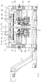
- the machine tool has a cast machine stand on, e.g. cast iron or polymer concrete.
- the machine stand consists of an essentially rectangular base part 10, vertical pillars 12 cast on at its four corners are.
- On top of the stand columns 12 is an upper stand part 14 placed and screwed to the pillars 12.
- the upper stand part 14 covers the roof entire area of the machine stand.
- the bottom of the stand top 14 is designed as a horizontal flat plate 16, stiffening ribs 18 formed on the upper side thereof are. Since the upper stand part 14 only at the four corners the support columns 12 is supported, the machine interior between the lower stand part 10 and the upper stand part 14 freely accessible from all four sides.
- the lower stand part 10 has a base in the longitudinal direction through tunnel 20 in which a chip conveyor 22 can be inserted. In the middle as a work space Serving area of the machine stand is in the lower part of the stand 10 a chip shaft 24 formed for the free chip fall vertically down into tunnel 20.
- Y-guides 26 At the bottom of the upper stand part 14 are horizontal extending Y-guides 26 attached to which hanging Y-carriage 28 are movable. At the bottom of the Y-carriage 28 horizontally extending Z-guides 30 are attached, which are perpendicular to the Y guides 26. On the Z guides 30 hanging Z-carriage 32 are movable, one horizontal working spindle 34 with its drive motor 36.
- This general machine tool concept can be varied Way flexible in the modular system with known Machine assemblies can be completed. This allows with a uniform machine stand and machine concept Machine tools for a wide variety of machining tasks produce. Below are some examples described and explained.
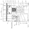
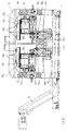
- Figures 1 a, b, c show an embodiment of the machine tool for turning wavy workpieces.
- Y-guide 26 On the underside of the upper stand part 14 is one over the full width, consisting of two profile rails Y-guide 26 attached. On the Y-guide 26 is by means of A Y-carriage 28 is attached to the roller bearings and is attached to it Bottom of a running at 90 ° to the Y guide 26 Z-guide 30 carries, which consists of two parallel rails consists. A Z carriage 32 can be moved on the Z guide 30 stored, the length of which is essentially the width of the Y-carriage 28 corresponds. At the bottom of the Z-carriage 32 hanging on one end with a horizontal work spindle 34 a drive motor 36 mounted. At the opposite end of the Z-carriage 32 is mounted a tailstock 42, the Axis is aligned with the axis of the work spindle 34.
- an X-slide 40 is movably supported, which is a tool turret 44 with horizontal turret axis.
- the tool turret 44 carries turning tools on its circumference.
- Blank workpieces are held in prisms on the conveyor track 46 fed to the machine tool.
- the Z-slide 32 will move in the Z direction using an NC-controlled drive, so that the work spindle 34 and the tailstock 42 in the Transport path 46 corresponding Z position come.
- the Y-carriage 28 is a hydraulic drive around the in Figure 1 b marked Y stroke, so that the work spindle 34 and the tailstock 42 over in the loading position the transport track 46 are.
- a workpiece blank is taken up by the conveyor 46 by a lifting device and lifted between work spindle 34 and tailstock 42. After clamping the blank between the work spindle 34 and the tailstock 42 moves the Y-carriage 28 back into the Working position.
- the drive motor 36 drives the work spindle 34 and the workpiece 50 on, the workpiece is by the Turning tool of the tool turret 44 processed, the Z feed by NC control of the Z-slide 32 and the X feed by an NC control of the X carriage 40.
- the Z slide 32 in the Z position of the second transport path 48 brought.
- the Y slide 28 guides the one shown in FIG. 1b Y stroke out, so that the workpiece 50 in the unloading position arrives via the transport track 48.
- the workpiece 50 can placed on the transport track 48 and removed.
- the feeding of the workpieces 50 through the transport path 46 and the removal of the workpieces 50 through the transport path 48 take place from the back of the machine stand.
- the operator has from the opposite front of the Machine stand free access and free insight into the Working space.
- the supply lines for driving the Carriage and the work spindle as well as for coolants and lubricants etc. can through the open right and left sides be fed.
- the entire base of the machine stand can be used for the Y-stroke and the Z-stroke, so that there is a compact machine construction with an inexpensive Ratio of footprint and travel distance results.
- the The width of the machine stand can be used for the Y stroke be so that loading and unloading station and work space optimal can be integrated into the machine stand.
- Like Figure 1a shows is a full utilization of the length of the machine stand possible for the Z-stroke. This is because that the drive motor 36 in the movement of the Z-carriage the right end position in Figure 1a through the open side of the Machine stand can move out.
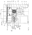
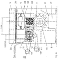
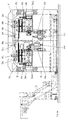
- Figures 2 a, b, c show an embodiment of the machine tool for turning short flange-shaped workpieces 50 in two setups.
- each of the Y guides 26a, 26b carries a Y-slide 28a or 28b.
- Z-slides 32a and 32b are Z-slides 32a and 32b, respectively arranged with a horizontal work spindle 34a or 34b.
- X-guides 38a and 38b An X-slide 40a or 40b each arranged, the tool turret 44 wear.
- the machining position of the work spindle 34a and the X-slide 40a is a transport path designed as an inlet trough 46 assigned to the loading and unloading station while a transport path 48 of the working position designed as a drainage channel the second work spindle 34b and the X-slide 40b is assigned.
- Workpiece raw parts 50 are fed via the transport path 46 and in the loading position in the machine stand brought.
- the work spindle 34a is driven by means of the Y-slide 28a and the Z slide 32a move into the loading position, so that the workpiece 50 is picked up and on the work spindle 34a can be tensioned.
- the work spindle 34a is then in the working position on the tool turret 44 of the X slide 40a driven.
- the workpiece 50 becomes from an end side edited here.
- the work spindles 34a and 34b aligned with each other and moved against each other by means of the Z-carriage 32a and 32b, so that the workpiece 50 from the first clamping in the Working spindle 34a in the second clamping in the working spindle 34b can be passed.
- the second is done Turning the second end of the workpiece 50 by NC control of the Z-carriage 32b and the X-carriage 40b. Is the second turning process is finished, that's it machined workpiece 50 by means of the Z-slide 32b and the Y carriage 28b brought into the unloading position and on the laxative transport track 48 filed.
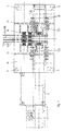
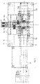
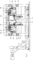
- Figures 3 a, b, c show a third embodiment, which for parallel preferably identical turning of two Workpieces.
- the upper stand part 14 has only one Y-guide 26 with a Y-slide 28. At the bottom of the Y-carriage 28 has a Z-guide 30 attached to it, however two Z-slides 32a and 32b are suspended.
- the Z slide 32a, 32b carries a work spindle 34a or 34b.
- Transport tracks 46a and 48b For feeding and removing the workpieces 50, two lead as Transport channels 46a and 46b are formed in the inlet channels Loading and unloading station and two drainage channels Transport tracks 48a and 48b guide the finished parts Workpieces.
- the transport tracks 46a and 48a run in parallel one above the other in one of the machining positions of the work spindle 34a corresponding Z position.
- the transport lanes 46b and 48b run parallel one above the other in one of the Machining position of the work spindle 34b corresponding Z position.
- the transport tracks 46a and 48a and the transport tracks 46b and 48b each have transfer positions in the Y direction are offset from each other.
- the machine tool of FIG. 3 works in the following way:
- the Y slide 28 is moved in the Y direction up to the in Figure 3b marked "loading stroke" transfer position of the feeding transport path 46a or 46b. In this position workpiece raw parts fed via the transport tracks 46a and 46b 50 passed and on the work spindles 34a and 34b excited. Then the Y-slide 28 is in the working position method. The on the work spindles 34a and 34b clamped workpieces 50 are rotated simultaneously by the Z-slides 32a and 32b and the X-slides 40a and 40b NC-controlled.
- the Y-carriage 28 is again in the loading and Unload station so that the work spindle 34a and 34b with the workpieces 50 via the transfer position of the respective laxative transport lanes 48a and 48b, so that the finished workpieces 50 on these transport tracks 48a or 48b can be stored.
- FIG. 4 a, b, c is a fourth embodiment of the machine tool shown, in which two flange-like workpieces can be machined in parallel in two setups.
- the machine tool points to the upper part of the stand 14 two Y-guides 26a and 26b with Y-slides 28a and 28b.
- Each of the Y slides 28a and 28b leads one Z-slide 32a or 32b.
- the turning is done by Working spindles 34a and 34b and X-slides 40a and 40b with respective tool turrets 44.
- Transport tracks 46a and 46b lead to the loading and unloading station, during transport lanes 48a and 48b from the loading and unloading station lead away.
- the transport tracks 46a, 46b, 48a, 48b correspond to the embodiment described in FIG. 3.
- Figure 5 a, b, c is another listing of the machine tool shown, in which four work spindles 34 are provided to reduce idle times in particular.
- the example is the machining of flange-like ones Workpieces 50 shown in two setups.
- Y-guides 26a, 26b with Y-slides 28a, 28b are provided.
- the Z-slides 32a, 32b carry one drive motor 36a or 36b and two in parallel juxtaposed, switchable by each Drive motor 36a or 36b drivable work spindles 34a1 and 34a2 or 34b1 and 34b2.
- the two edits is each assigned an X-slide 40a or 40b, which in the illustrated example receives a tool carrier block 52.
- the loading and unloading station is included with each Z-slide 32a, 32b equipped with a double transfer position.
- the workpiece raw parts are via a transport track designed as an inlet trough 46b fed and after processing via a as Discharge channel trained conveyor 48a transported away.
- the machine tool shown in FIG. 5 operates in the following Wise:
- the workpiece raw parts are fed via the transport path 46b, with two workpiece blanks in each case in the transfer position the loading and unloading station.
- the Z slide 32b is moved to the loading position by means of the Z stroke and the Y stroke process where the two workpiece blanks on the Working spindles 34b1 and 34b2 can be clamped.
- the Z-slide 32b is drawn into the one drawn in FIG. 5b Move to the position in which the work spindle is located 34b2 over the tool carrier block 52b of the X slide 40b is located.
- the drive motor 36b drives the work spindle 34b2 and the workpiece clamped on this work spindle 50 is rotated.
- the Z-slides 32a and 32b only have to once for two workpieces 50 in the loading and unloading position can be moved, reducing idle times become.
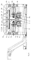
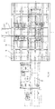
- Figures 6 a, b, c show a sixth embodiment of the machine tool with four work spindles, two each flange-like workpieces simultaneously in parallel in two setups can be edited.
- Y-guides 26a, 26b On the underside of the upper part 14 of the stand are two Y-guides 26a, 26b provided with Y-slides 28a, 28b. At the bottom of the Y-carriage 28a, 28b is on Z-guides 30a, 30b, respectively a Z carriage can be moved at right angles to the Y guides 26a, 26b 32a, 32b arranged. At the bottom of the Z-slide 32a and 32b are next to each other an X correction slide 54a and 54b and a Z correction slide 56a or 56b arranged. In the X correction slide 54a or 54b is a first work spindle 34a1 or 34b1 and in the Z correction slide 56a and 56b a second work spindle 34a2 or 34b2 stored.
- the two work spindles 34a1 and 34a2 or 34b1 and 34b2 are axially parallel and horizontal in the Z direction arranged.
- the X correction slide 54a or 54b is can be moved vertically in the X direction on the Z slide 32a or 32b guided.
- X correction guides 58a or 58b which are arranged vertically on the Z-slide 32a or 32b and guide the X correction slide 54a or 54b.
- An on X-correction drive arranged on the Z-slide 32a or 32b 60a or 60b serves to move the X correction slide 54 in the vertical X direction with respect to the Z slide 32a or 32b.
- the Z correction slide 56a or 56b is horizontal in the Z direction mounted on the Z-slide 32a or 32b.
- Z-correction guides 62a and 62b on the underside of the Z-slide 32a and 32b are attached and the Z-correction slide 56a and 56b lead.
- One on the Z slide 32a or 32b attached Z-correction drive 64a or 64b is used to move the Z correction slide 56a or 56b compared to the Z-slide 32a or 32b.
- the work spindles 34a1 and 34a2 or 34b1 and 34b2 each assigned a vertically movable X-slide 40a and 40b arranged.
- the X-slide 40a or 40b carries a tool turret 44a or 44b horizontal axis of rotation.
- the tool turret 44a or 44b carries two machining tools in each switch position parallel to each other and at a distance between the work spindles 34a1 and 34a2 or 34b1 and 34b2 corresponding distance are arranged side by side.
- the tool turret 44a or 44b is essentially square and has four switch positions on each side of the turret 44a or 44b two tools are arranged.
- the machine tool of FIG. 6 operates in the following way.
- the transfer position pick-up position
- two pipe sections are positioned next to each other parallel to the axis.
- the Y carriage 28b moves to the transfer position and picks up these two pieces of pipe that are on the work spindles 34b1 and 34b2 can be clamped in a first setting.
- the Y-slide 28b moves into the machining position in which the workpiece tube parts in tools of the tool turret 44b are assigned. Now the workpieces are turned simultaneously and in parallel on the work spindles 34b1 and 34b2 through the tools of the tool turret 44b.
- the Processing takes place under NC control, whereby the drive of the Z-slide 32b the Z-stroke and the drive of the X-slide 40b cause the X stroke of the turning operation.
- the X correction slide 54b and the Z correction slide 56b provided to different Cutting properties of the on the work spindle 34a1 and the tool used on the work spindle 34a2, e.g. B. to compensate for different tool wear.
- the Z hub for turning on the work spindle 34b1 by the Z-slide 32b certainly.
- This Z stroke of the Z slide can be used for the work spindle 34b2 32b additionally by the Z correction slide 56b Can be corrected under NC control.
- the X-Hub for turning is processed by the X-slide 40b on the Working spindle 34b2 determined.
- the work spindle 34b1 can be moved through the X-slide 40b specified X stroke additionally by the X correction slide 54b can be corrected under NC control. That way you can Machining deviations between the two work spindles 34b1 and 34b2 both in the direction of the Z axis and in the X axis to be corrected.
- the workpieces After finishing the machining of the workpieces in the clamping The workpieces are on the work spindles 34b1 and 34b2 passed to the work spindles 34a1 and 34a2 and there curious; excited. The workpieces are in this second clamping in a corresponding way from their opposite axial Machined from the front. After finishing editing in The finished workpieces become this second clamping by means of the Y slide 28a into the delivery position of the loading and Unloading station driven and there on the trained as a gutter Precast conveyor 48 deposited.
- pro Processing cycle processed two workpieces each. Thereby The finished part output and the machining cycle are doubled halved per workpiece. It is possible in this way flange-like workpieces, e.g. B. races for rolling bearings with a cycle of 8 to 10 seconds per workpiece.
- Figures 7 a, b, c show a modification of the machine tool of Figure 6.
- the execution of Figure 7 agrees with the Execution of Figure 6 largely match. Contrary to that The embodiment of Figure 6 is, however, on the X-slide 40a and 40b in place of the tool turret 44a and 44b, respectively a tool carrier block 52a or 52b attached.
- the Processing is otherwise done in the same way as this is described for the embodiment of Figure 6.
- the machine tools are each designed for turning. Accordingly is an NC-controlled feed only for the X axes and the Z axes are provided.
- Y feed can also be done with an NC control be equipped. It can then also be non-rotationally symmetrical Edits are carried out.
- work spindles 34 with workpiece clamping devices for the turning can also work as the work spindles 34 Drilling spindles or milling spindles can be formed.
- Drilling spindles or milling spindles can be formed.
- this Trap is the assigned X slide for workpiece clamping educated.
- Other possible combinations known assemblies of processing machines result for the specialist in an obvious manner.
Landscapes
- Engineering & Computer Science (AREA)
- Mechanical Engineering (AREA)
- Turning (AREA)
- Machine Tool Units (AREA)
Applications Claiming Priority (2)
| Application Number | Priority Date | Filing Date | Title |
|---|---|---|---|
| DE19803563 | 1998-01-30 | ||
| DE19803563A DE19803563C1 (de) | 1998-01-30 | 1998-01-30 | Werkzeugmaschine, insbesondere Drehmaschine mit wenigstens einer hängend angeordneten horizontalen Arbeitsspindel |
Publications (3)
| Publication Number | Publication Date |
|---|---|
| EP0933162A2 true EP0933162A2 (fr) | 1999-08-04 |
| EP0933162A3 EP0933162A3 (fr) | 2001-05-23 |
| EP0933162B1 EP0933162B1 (fr) | 2006-09-06 |
Family
ID=7856112
Family Applications (1)
| Application Number | Title | Priority Date | Filing Date |
|---|---|---|---|
| EP98123879A Expired - Lifetime EP0933162B1 (fr) | 1998-01-30 | 1998-12-16 | Machine-outil |
Country Status (4)
| Country | Link |
|---|---|
| US (1) | US6161457A (fr) |
| EP (1) | EP0933162B1 (fr) |
| DE (1) | DE19803563C1 (fr) |
| ES (1) | ES2271981T3 (fr) |
Cited By (2)
| Publication number | Priority date | Publication date | Assignee | Title |
|---|---|---|---|---|
| EP1413395A1 (fr) * | 2002-10-24 | 2004-04-28 | Emag Maschinenfabrik Gmbh | Machine-outil |
| WO2006106137A1 (fr) * | 2005-04-08 | 2006-10-12 | Buderus Schleiftechnik Gmbh | Machine-outil a porte-piece horizontal et porte-outil a deplacement vertical |
Families Citing this family (10)
| Publication number | Priority date | Publication date | Assignee | Title |
|---|---|---|---|---|
| FR2801823B1 (fr) * | 1999-09-07 | 2002-02-15 | Renault Automation Comau | Machine-outil d'usinage de type bibroche |
| DE19959961A1 (de) * | 1999-12-13 | 2001-06-28 | Index Werke Kg Hahn & Tessky | Drehmaschine |
| AU2001291659A1 (en) * | 2000-06-29 | 2002-01-08 | Huller Hille Gmbh | Machine tool for processing work pieces on at least three axes |
| DE10330909B4 (de) * | 2003-07-07 | 2007-02-08 | Stama Maschinenfabrik Gmbh | Werkzeugmaschine und Verfahren zur spanabhebenden Bearbeitung von Werkstücken |
| DE102004044098A1 (de) * | 2004-09-08 | 2006-03-23 | Chiron-Werke Gmbh & Co. Kg | Werkzeugmaschine mit einem Maschinenfuß |
| DE102005021639A1 (de) * | 2005-05-06 | 2006-11-09 | Satisloh Gmbh | Hochleistungs-Fräs- und Drehmaschine sowie Verfahren zur Bearbeitung von Brillengläsern |
| DE102005021638B4 (de) * | 2005-05-06 | 2007-03-29 | Satisloh Gmbh | Drehmaschine zur Bearbeitung von optischen Werkstücken |
| US20090293688A1 (en) * | 2008-05-30 | 2009-12-03 | Benedikt Nillies | Metal forming machine and method for spinning/flow forming |
| CN102990088A (zh) * | 2012-11-27 | 2013-03-27 | 无锡市彩云机械设备有限公司 | 一种立式车床 |
| DE102015004211B4 (de) * | 2015-03-31 | 2017-03-23 | Emag Holding Gmbh | Nach dem Pick-up-Verfahren arbeitende Schleifmaschine |
Family Cites Families (25)
| Publication number | Priority date | Publication date | Assignee | Title |
|---|---|---|---|---|
| GB1202469A (en) * | 1967-11-25 | 1970-08-19 | Schiess Ag | Double-column planer-type milling machines |
| US3990133A (en) * | 1974-01-15 | 1976-11-09 | Gildemeister Aktiengesellschaft | Multi-station machine tool with pairs of tool-and work-spindles |
| JPS52108588A (en) * | 1976-03-10 | 1977-09-12 | Okuma Mach Works Ltd | Value control lathe |
| US4159660A (en) * | 1978-02-21 | 1979-07-03 | Ex-Cell-O Corporation | Biaxial turning machine with means for bidirectional independent tool compensation |
| US4182205A (en) * | 1978-04-27 | 1980-01-08 | Baker Gary L | Turret type metal working machine |
| DE2853949C2 (de) * | 1978-12-14 | 1982-12-02 | Index-Werke Kg Hahn & Tessky, 7300 Esslingen | Einrichtung zum Be- und Entladen rotationssymmetrischer Werkstücke |
| US4343206A (en) * | 1980-06-12 | 1982-08-10 | The United States Of America As Represented By The United States Department Of Energy | Slide system for machine tools |
| DE3416660A1 (de) * | 1984-05-05 | 1985-11-07 | J.G. Weisser Söhne Werkzeugmaschinenfabrik GmbH & Co. KG, 7742 St Georgen | Drehmaschine |
| JPS6263033A (ja) * | 1985-09-11 | 1987-03-19 | Kitamura Kikai Kk | 多面加工装置 |
| JPH0643002B2 (ja) * | 1986-02-17 | 1994-06-08 | 株式会社森精機製作所 | Nc旋盤 |
| US5025690A (en) * | 1986-11-06 | 1991-06-25 | The Warner & Swasey Company | Vertical spindle turret lathe |
| US4813315A (en) * | 1987-05-18 | 1989-03-21 | Yachiyoda Kogyo Co., Ltd. | Multi-spindle lathe |
| DE3732559C2 (de) * | 1987-09-26 | 1995-06-29 | Hessische Apparatebau | Fertigungseinheit |
| JPH071213Y2 (ja) * | 1988-02-17 | 1995-01-18 | 本田技研工業株式会社 | 工作機械のチャック装置 |
| AU3218189A (en) * | 1988-05-31 | 1990-01-05 | Gordon T. Brown | Gantry robot construction |
| CH677746A5 (fr) * | 1989-01-25 | 1991-06-28 | Dixi Sa | |
| DE3930489C2 (de) * | 1989-09-12 | 1993-11-18 | Boehringer Werkzeugmaschinen | Verfahren und Werkzeugmaschine zum Fertigbearbeiten von Lagerzapfen |
| JP2692011B2 (ja) * | 1990-02-09 | 1997-12-17 | 三菱電機株式会社 | 数値制御自動プログラミング装置 |
| US5704262A (en) * | 1991-11-11 | 1998-01-06 | Pcc Pittler Maschinenfabrik Gmbh | Multiple-spindle lathe |
| AU657852B2 (en) * | 1992-04-10 | 1995-03-23 | Emag Holding Gmbh | Machining centre constructed from assemblies |
| US5314397A (en) * | 1992-07-31 | 1994-05-24 | Ford Motor Company | Positioning apparatus for multiple-spindle machining |
| DE4229423C3 (de) * | 1992-09-03 | 1998-10-01 | Index Werke Kg Hahn & Tessky | Drehmaschine |
| DE4307482A1 (de) * | 1993-03-10 | 1994-09-22 | Max Rhodius Gmbh | Werkzeugmaschine |
| US5782151A (en) * | 1995-08-07 | 1998-07-21 | Kitagawa Iron Works Co., Ltd. | Workpiece transfer apparatus |
| DE19651474C2 (de) * | 1995-12-20 | 2000-05-18 | Ilg Gmbh | Werkzeugmaschine |
-
1998
- 1998-01-30 DE DE19803563A patent/DE19803563C1/de not_active Expired - Lifetime
- 1998-12-16 ES ES98123879T patent/ES2271981T3/es not_active Expired - Lifetime
- 1998-12-16 EP EP98123879A patent/EP0933162B1/fr not_active Expired - Lifetime
-
1999
- 1999-01-26 US US09/238,089 patent/US6161457A/en not_active Expired - Fee Related
Cited By (2)
| Publication number | Priority date | Publication date | Assignee | Title |
|---|---|---|---|---|
| EP1413395A1 (fr) * | 2002-10-24 | 2004-04-28 | Emag Maschinenfabrik Gmbh | Machine-outil |
| WO2006106137A1 (fr) * | 2005-04-08 | 2006-10-12 | Buderus Schleiftechnik Gmbh | Machine-outil a porte-piece horizontal et porte-outil a deplacement vertical |
Also Published As
| Publication number | Publication date |
|---|---|
| ES2271981T3 (es) | 2007-04-16 |
| DE19803563C1 (de) | 1999-04-08 |
| US6161457A (en) | 2000-12-19 |
| EP0933162B1 (fr) | 2006-09-06 |
| EP0933162A3 (fr) | 2001-05-23 |
Similar Documents
| Publication | Publication Date | Title |
|---|---|---|
| EP2812152B1 (fr) | Machine de rodage à plusieurs postes de travail et table rotative | |
| DE4212175C2 (fr) | ||
| EP2263827B1 (fr) | Appareil pour usiner des pièces | |
| DE602006000545T2 (de) | Bearbeitungszentrum mit zwei Arbeitseinheiten mit Mitteln zur Handhabung des Werkstücks | |
| EP3535092B1 (fr) | Machine de pierrage avec une pluralité de postes de travail | |
| EP1291122A2 (fr) | Centre d'usinage pour fraisage et forage | |
| EP1413395A1 (fr) | Machine-outil | |
| EP0908269A2 (fr) | Disposition de machines-outils avec deux unités d'usinage opposées | |
| EP0933162B1 (fr) | Machine-outil | |
| EP0967038B1 (fr) | Dispositif d' usinage de pièces par enlèvement de matière | |
| EP0612278B1 (fr) | Tour automatique multibroche | |
| DE3722180A1 (de) | Transfermaschine | |
| DE4310038A1 (de) | Drehmaschine mit zwei Werkstückspindeln | |
| DE4031911A1 (de) | Vorrichtung zum bearbeiten von stangen | |
| EP1294530A2 (fr) | Machine-outil destinee a l'usinage au moins triaxial de pieces | |
| DE102005061586A1 (de) | Drehbank, und Bearbeitungssystem mit einer Drehbank | |
| DE10058627A1 (de) | Drehmaschine | |
| DE10235518B4 (de) | Verfahren und Vorrichtung zur Werkstück-Bearbeitung | |
| EP1985409A1 (fr) | Machine transfert flexible avec porte-pièces mobiles | |
| EP1095730A2 (fr) | Dispositif pour l'usinage de pièces et procédé d'usinage de pièces à l'aide d'un tel dispositif | |
| WO2017050835A2 (fr) | Machine-outil | |
| DE19652460C1 (de) | Werkzeugmaschine mit mehreren Spindeln | |
| DE19607883A1 (de) | Vertikal-Drehmaschine | |
| DE102011118170B4 (de) | Flachbettdrehmaschine | |
| DE102004052516A1 (de) | Fertigungseinrichtung |
Legal Events
| Date | Code | Title | Description |
|---|---|---|---|
| PUAI | Public reference made under article 153(3) epc to a published international application that has entered the european phase |
Free format text: ORIGINAL CODE: 0009012 |
|
| AK | Designated contracting states |
Kind code of ref document: A2 Designated state(s): ES FR GB IT |
|
| AX | Request for extension of the european patent |
Free format text: AL;LT;LV;MK;RO;SI |
|
| PUAL | Search report despatched |
Free format text: ORIGINAL CODE: 0009013 |
|
| AK | Designated contracting states |
Kind code of ref document: A3 Designated state(s): AT BE CH CY DE DK ES FI FR GB GR IE IT LI LU MC NL PT SE |
|
| AX | Request for extension of the european patent |
Free format text: AL;LT;LV;MK;RO;SI |
|
| AKX | Designation fees paid | ||
| 17P | Request for examination filed |
Effective date: 20011026 |
|
| RBV | Designated contracting states (corrected) |
Designated state(s): ES FR GB IT |
|
| REG | Reference to a national code |
Ref country code: DE Ref legal event code: 8566 |
|
| GRAP | Despatch of communication of intention to grant a patent |
Free format text: ORIGINAL CODE: EPIDOSNIGR1 |
|
| GRAS | Grant fee paid |
Free format text: ORIGINAL CODE: EPIDOSNIGR3 |
|
| GRAA | (expected) grant |
Free format text: ORIGINAL CODE: 0009210 |
|
| AK | Designated contracting states |
Kind code of ref document: B1 Designated state(s): ES FR GB IT |
|
| REG | Reference to a national code |
Ref country code: GB Ref legal event code: FG4D Free format text: NOT ENGLISH |
|
| GBT | Gb: translation of ep patent filed (gb section 77(6)(a)/1977) |
Effective date: 20061122 |
|
| ET | Fr: translation filed | ||
| REG | Reference to a national code |
Ref country code: ES Ref legal event code: FG2A Ref document number: 2271981 Country of ref document: ES Kind code of ref document: T3 |
|
| PLBE | No opposition filed within time limit |
Free format text: ORIGINAL CODE: 0009261 |
|
| STAA | Information on the status of an ep patent application or granted ep patent |
Free format text: STATUS: NO OPPOSITION FILED WITHIN TIME LIMIT |
|
| 26N | No opposition filed |
Effective date: 20070607 |
|
| PGFP | Annual fee paid to national office [announced via postgrant information from national office to epo] |
Ref country code: FR Payment date: 20110107 Year of fee payment: 13 |
|
| PGFP | Annual fee paid to national office [announced via postgrant information from national office to epo] |
Ref country code: GB Payment date: 20101109 Year of fee payment: 13 |
|
| PGFP | Annual fee paid to national office [announced via postgrant information from national office to epo] |
Ref country code: IT Payment date: 20101228 Year of fee payment: 13 |
|
| PGFP | Annual fee paid to national office [announced via postgrant information from national office to epo] |
Ref country code: ES Payment date: 20101222 Year of fee payment: 13 |
|
| GBPC | Gb: european patent ceased through non-payment of renewal fee |
Effective date: 20111216 |
|
| REG | Reference to a national code |
Ref country code: FR Ref legal event code: ST Effective date: 20120831 |
|
| PG25 | Lapsed in a contracting state [announced via postgrant information from national office to epo] |
Ref country code: GB Free format text: LAPSE BECAUSE OF NON-PAYMENT OF DUE FEES Effective date: 20111216 |
|
| PG25 | Lapsed in a contracting state [announced via postgrant information from national office to epo] |
Ref country code: IT Free format text: LAPSE BECAUSE OF NON-PAYMENT OF DUE FEES Effective date: 20111216 |
|
| PG25 | Lapsed in a contracting state [announced via postgrant information from national office to epo] |
Ref country code: FR Free format text: LAPSE BECAUSE OF NON-PAYMENT OF DUE FEES Effective date: 20120102 |
|
| REG | Reference to a national code |
Ref country code: ES Ref legal event code: FD2A Effective date: 20130703 |
|
| PG25 | Lapsed in a contracting state [announced via postgrant information from national office to epo] |
Ref country code: ES Free format text: LAPSE BECAUSE OF NON-PAYMENT OF DUE FEES Effective date: 20111217 |