EP0933168A2 - Dispositif de serrage - Google Patents
Dispositif de serrage Download PDFInfo
- Publication number
- EP0933168A2 EP0933168A2 EP99101165A EP99101165A EP0933168A2 EP 0933168 A2 EP0933168 A2 EP 0933168A2 EP 99101165 A EP99101165 A EP 99101165A EP 99101165 A EP99101165 A EP 99101165A EP 0933168 A2 EP0933168 A2 EP 0933168A2
- Authority
- EP
- European Patent Office
- Prior art keywords
- clamping device
- elements
- shell
- end position
- head
- Prior art date
- Legal status (The legal status is an assumption and is not a legal conclusion. Google has not performed a legal analysis and makes no representation as to the accuracy of the status listed.)
- Withdrawn
Links
Images

Classifications
-
- B—PERFORMING OPERATIONS; TRANSPORTING
- B25—HAND TOOLS; PORTABLE POWER-DRIVEN TOOLS; MANIPULATORS
- B25B—TOOLS OR BENCH DEVICES NOT OTHERWISE PROVIDED FOR, FOR FASTENING, CONNECTING, DISENGAGING, OR HOLDING
- B25B5/00—Clamps
- B25B5/06—Arrangements for positively actuating jaws
- B25B5/12—Arrangements for positively actuating jaws using toggle links
- B25B5/122—Arrangements for positively actuating jaws using toggle links with fluid drive
-
- B—PERFORMING OPERATIONS; TRANSPORTING
- B25—HAND TOOLS; PORTABLE POWER-DRIVEN TOOLS; MANIPULATORS
- B25B—TOOLS OR BENCH DEVICES NOT OTHERWISE PROVIDED FOR, FOR FASTENING, CONNECTING, DISENGAGING, OR HOLDING
- B25B5/00—Clamps
- B25B5/16—Details, e.g. jaws, jaw attachments
Definitions
- the invention relates to a clamping device for clamping Workpieces according to the preamble of the independent claim 1.
- Such clamping devices are, for example, according to DE-U-92 15 151.5 known.
- the invention is accordingly based on the object of a tensioning device of the type mentioned above with regard to their end position interrogation device to train and improve in such a way that they can easily and without auxiliary tools to changed installation conditions, Adjustment paths or operating conditions of the Clamping device is adaptable.
- This task is on and with a clamping device of the generic type Type solved according to the invention in that the end position interrogation device from one of the end position query elements laterally receiving half-shell and this from at least a head part and a connecting part is formed, head part and connecting part to each other by means of releasable connecting elements can be aligned aligned and with connecting and fixing elements are provided for the head piece of the clamping device.
- Advantageous further developments and embodiments result according to the subclaims.
- This training according to the invention is a kind of variable-length carrier for the actual end position query elements created together with these query elements (e.g. microswitches, sensors or the like.) a total in insert the clamping device head piece and position it precisely easily lockable cassette.
- An embodiment is preferred in which between head and Connection part at least one with corresponding connecting elements provided intermediate part can be used because this Embodiment the greater adaptability to different lengths Offers recesses of clamping devices and the head and Connection parts can always be maintained without change.
- the manufacturer can restrict himself to one of the two parts with different lengths to produce and keep ready.
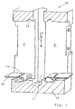
- Fig. 1 the interior view is in principle in a half section a part of a clamping device head piece 10 is shown, with a range of motion in the jig head 10 for a linear actuator that can be actuated by a drive A.
- LS is designated 27.
- Such a linear actuator LS moves itself in the direction of arrow 28.
- a sensor G arranged laterally out of the movement space 27 stands out and explained in more detail below End position query element 2 (here microswitch) actuated.
- End of the linear actuator LS is (not particularly shown) with coupled to the swivel arm SA in bearing L, the via actuator LS between two end positions (see Fig. 7) is adjustable, which must be queried.
- an end position interrogation device consists, as shown, for example, of a half-shell 1, which is open to the movement space 27 of the linear actuator LS and to a flat side.
- an end position sensing device 2 In the interior of the half-shell 1, two end position sensing elements 2 are arranged, which are electrically connected by means of cables 5 to a plug contact 6, which makes the signals of the end position sensing elements 2 accessible.
- This plug contact 6 is arranged at a rear opening 7 of the half-shell 1.
- the cables 5 are laid freely in a channel-like area 4, are flexible and thus allow the position of the end position interrogation element 2 to be changed along the direction of movement 28 of the linear actuator LS.
- the end position query element 2 are held within the half-shell 1 by means of pins, not shown here, arranged on the shell side, which are inserted into the bores 3 of a row of holes in the desired position.
- each of the two end position sensing elements 2 is laterally fixed by inserting the entire end position sensing device into the recess 9 or 9 'of the clamping device head piece 10, as the edge 8 of the half-shell 1 advantageously lies at the same height as the surface of the end position sensing elements 2 (see Fig. 8). Falling out of the end position interrogation elements 2 from the half-shell 1 is thus reliably prevented by their walls after their insertion into one of the recesses 9, 9 '.
- the head part 11 and connecting part 13 by means of releasable connecting elements 14, 19; 15, 16 can be connected to one another and with connecting and fixing elements 17,21 to the head piece 10 are provided.
- the half-shell 1 is constructed modularly from the head part 11, intermediate part / s 12 and connecting part 13.
- the half-shell 1 is segmented in such a way that the same or different lengths of individual parts 11, 12, 13 result which, when put together, result in a half-shell 1 which can be adapted to the required overall lengths and setting ranges of the end position query elements 2.
- only a head part 11 and a connection part 13 are joined, these two parts each having the bores 3 for inserting the end position interrogation switch 2.
- either the head part 11 and the connecting part 13 can be extended, or one or more intermediate parts 12 are inserted between the head part 11 and the connecting part 13, which together with the head part 11 and the connecting part 13 then, according to the required distance, the adjustment path via arrangement of Define end position query elements 2.
- the head part 11 and the connecting part 13 can always be of the same length and for each application with one or more intermediate parts 12 from a series, differently long intermediate parts 12 can also be fitted together.
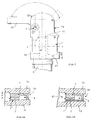
- connection between head part 11, connecting part 13 or intermediate part 12, as shown in FIGS. 4a and 4b by means of pins 14 which are in corresponding bores (not shown) of the adjacent part can be inserted.
- FIG. 4c or 4b can be a latchable Connection by means of a locking hook 15 and a locking recess 16 can be provided at the neighboring part.
- a precise adjustment of the end position interrogation device for Linear actuator and its encoder G can be advantageously simple Realize that on the outside and on top of the half shell 1 a rounded cam as a connection and fixing element 17th is arranged, the in the intended plug-in state End position interrogation device in the recess 9 or 9 'in a corresponding recess 18 engages the head 10. This is the exact insertion position of the end position interrogation device always guaranteed safely and without complex adjustment. It goes without saying that in kinematic reversal also a cam 19 in the wall of the recess 9 or 9 ' a corresponding recess of the half-shell 1 can lock.
- a leaf spring 22 between half shell 1 and wall of recess 9, 9 ' are arranged so that they are fixed in the recess 9, 9' is and with an associated cam as a fixing element 21 on the connecting part 13 of the half-shell 1 in the inserted state locked.
- such a spring element also be integrally formed on the connecting part 13, wherein the resilient locking part 23 on an edge 24 of the recess 9, 9 ' locked.
- a stop edge 25 is provided the flank of a common locking groove opposite the edge 24 25 'forms.
- FIGS. 8A, B which represents a section along line II in FIG. 7, in which the arrangement of the end position interrogation device is only indicated by dashed lines.
- 8A makes it clear that the actual query elements 2, which are attached to the half-shell 1 consisting of the described individual parts as carriers, are held in their inserted position by the adjacent flank of the head piece 10.
- FIG. 8B it is advantageously provided, according to FIG. 8B, to assign the half-shell 1 a correspondingly dimensioned spacing plate 1 'on its flank, which in a suitable manner on the one or the other side of the half-shell is connected to it.
Landscapes
- Engineering & Computer Science (AREA)
- Mechanical Engineering (AREA)
- Jigs For Machine Tools (AREA)
- Clamps And Clips (AREA)
- Transmission And Conversion Of Sensor Element Output (AREA)
Applications Claiming Priority (2)
| Application Number | Priority Date | Filing Date | Title |
|---|---|---|---|
| DE1998103513 DE19803513A1 (de) | 1998-01-30 | 1998-01-30 | Modulare Endstellungsabfrageeinrichtung |
| DE19803513 | 1998-01-30 |
Publications (2)
| Publication Number | Publication Date |
|---|---|
| EP0933168A2 true EP0933168A2 (fr) | 1999-08-04 |
| EP0933168A3 EP0933168A3 (fr) | 2001-05-02 |
Family
ID=7856075
Family Applications (1)
| Application Number | Title | Priority Date | Filing Date |
|---|---|---|---|
| EP99101165A Withdrawn EP0933168A3 (fr) | 1998-01-30 | 1999-01-22 | Dispositif de serrage |
Country Status (2)
| Country | Link |
|---|---|
| EP (1) | EP0933168A3 (fr) |
| DE (1) | DE19803513A1 (fr) |
Cited By (5)
| Publication number | Priority date | Publication date | Assignee | Title |
|---|---|---|---|---|
| WO2002074503A1 (fr) * | 2001-03-16 | 2002-09-26 | Phd, Inc. | Prehenseur dote d'un ensemble de capteurs reglables |
| EP1092509A3 (fr) * | 1999-10-15 | 2003-10-01 | SMC Kabushiki Kaisha | Dispositif de serrage |
| US6641189B2 (en) | 2001-03-16 | 2003-11-04 | Phd, Inc. | Article sensor assembly |
| EP1700671A3 (fr) * | 2005-03-07 | 2006-09-27 | UNIVER S.p.A. | Dispositif de maintien pour pièces à travailler avec unité de contrôle démontable |
| CN114654282A (zh) * | 2022-04-28 | 2022-06-24 | 朝华力拓精密智能(深圳)有限公司 | 一种用于手机壳加工定位工装-双气缸滑台 |
Family Cites Families (12)
| Publication number | Priority date | Publication date | Assignee | Title |
|---|---|---|---|---|
| US3621172A (en) * | 1969-04-21 | 1971-11-16 | Raymond Control Sytems Inc | Switch-actuating means and adjustable camming construction |
| US4663505A (en) * | 1986-05-22 | 1987-05-05 | Litton Systems, Inc. | Interlock switch base plate assembly |
| DE8811579U1 (de) * | 1988-09-13 | 1990-01-11 | De-Sta-Co Metallerzeugnisse Gmbh, 6000 Frankfurt | Spannvorrichtung |
| DE9016781U1 (de) * | 1990-12-12 | 1992-04-09 | De-Sta-Co Metallerzeugnisse Gmbh, 6000 Frankfurt | Spannvorrichtung |
| DE9105755U1 (de) * | 1991-05-08 | 1991-06-27 | De-Sta-Co Metallerzeugnisse Gmbh, 6000 Frankfurt | Spannvorrichtung |
| DE9215151U1 (de) * | 1992-05-14 | 1993-01-21 | De-Sta-Co Metallerzeugnisse Gmbh, 6000 Frankfurt | Spannvorrichtung |
| DE9311132U1 (de) * | 1993-07-26 | 1993-09-09 | Tünkers Maschinenbau GmbH, 40880 Ratingen | Kniehebelspannvorrichtung für den Karosseriebau |
| DE29504987U1 (de) * | 1995-03-24 | 1995-07-06 | Dewert Antriebs- Und Systemtechnik Gmbh & Co. Kg, 32278 Kirchlengern | Elektromotorischer Möbelantrieb |
| IT240544Y1 (it) * | 1996-03-25 | 2001-04-02 | Ciar Srl | Attuatore lineare con microinterruttori di fine corsa ad elevatasemplicita'di regolazione. |
| DE29614630U1 (de) * | 1996-08-23 | 1998-01-02 | Werner Turck GmbH & Co. KG, 58553 Halver | Anordnung zur sensorischen Ermittlung der Bewegungsendstellungen eines Kraftspanners |
| DE29700981U1 (de) * | 1997-01-22 | 1997-03-13 | DE-STA-CO Metallerzeugnisse GmbH, 61449 Steinbach | Induktive Endstellungsabfrageeinrichtung |
| DE29718644U1 (de) * | 1997-10-21 | 1997-12-11 | Tünkers Maschinenbau GmbH, 40880 Ratingen | Abfragekassette |
-
1998
- 1998-01-30 DE DE1998103513 patent/DE19803513A1/de not_active Withdrawn
-
1999
- 1999-01-22 EP EP99101165A patent/EP0933168A3/fr not_active Withdrawn
Cited By (5)
| Publication number | Priority date | Publication date | Assignee | Title |
|---|---|---|---|---|
| EP1092509A3 (fr) * | 1999-10-15 | 2003-10-01 | SMC Kabushiki Kaisha | Dispositif de serrage |
| WO2002074503A1 (fr) * | 2001-03-16 | 2002-09-26 | Phd, Inc. | Prehenseur dote d'un ensemble de capteurs reglables |
| US6641189B2 (en) | 2001-03-16 | 2003-11-04 | Phd, Inc. | Article sensor assembly |
| EP1700671A3 (fr) * | 2005-03-07 | 2006-09-27 | UNIVER S.p.A. | Dispositif de maintien pour pièces à travailler avec unité de contrôle démontable |
| CN114654282A (zh) * | 2022-04-28 | 2022-06-24 | 朝华力拓精密智能(深圳)有限公司 | 一种用于手机壳加工定位工装-双气缸滑台 |
Also Published As
| Publication number | Publication date |
|---|---|
| DE19803513A1 (de) | 1999-08-05 |
| EP0933168A3 (fr) | 2001-05-02 |
Similar Documents
| Publication | Publication Date | Title |
|---|---|---|
| EP0219570B1 (fr) | Appareil de commutation | |
| EP2661193B1 (fr) | Dispositif d'accouplement pour tiroirs | |
| EP2661194B1 (fr) | Dispositif pour ajuster le front d'un tiroir | |
| DE69837736T2 (de) | Sicherheitsschalter | |
| DE19646645C2 (de) | Behälter | |
| WO1997040247A2 (fr) | Dispositif de fermeture a barres concu pour etre monte par encliquetage | |
| EP1895067A1 (fr) | Dispositif destiné à l'actionnement d'une chasse d'eau de WC réalisé dans une technique de rinçage à deux quantités | |
| EP0727797A1 (fr) | Interrupteur de sécurité | |
| DE29507658U1 (de) | Vorrichtung zum Verstellen einer Sitz- und/oder Rückenschale | |
| EP1620611B2 (fr) | Dispositif de fixation d'une paroi coulissante | |
| DE19938378A1 (de) | Vorrichtung zum Öffnen und Verschließen einer Öffnung in einer Wandung mittels einer Schiebetür | |
| DE9215151U1 (de) | Spannvorrichtung | |
| DE4417039C2 (de) | Bandaufnahmeelement | |
| DE19753574C2 (de) | Bohrer mit Vorrichtung zur Begrenzung der Bohrtiefe | |
| DE19803513A1 (de) | Modulare Endstellungsabfrageeinrichtung | |
| DE29921641U1 (de) | Haushalts-Einbaukühlschrank mit Vorrichtungen zur Feinregulierung der Position der vorderen Abdeckplatten | |
| DE3913319C2 (fr) | ||
| DE69703026T2 (de) | Schlüsselsicherheitsschalter | |
| AT502259B1 (de) | Vorrichtung zum halten von in schienen geführten laufwerken | |
| DE3145954C2 (de) | Elektrischer Kippschalter, insbesondere für Kraftfahrzeuge | |
| EP1617087A1 (fr) | Dispositif de support | |
| WO2007124916A2 (fr) | Dispositif de verrouillage d'une porte coulissante | |
| EP0530527B1 (fr) | Moyens de serrage | |
| DE69802628T2 (de) | Unterputzspülkasten für ein Spülsystem | |
| DE3822129C2 (fr) |
Legal Events
| Date | Code | Title | Description |
|---|---|---|---|
| PUAI | Public reference made under article 153(3) epc to a published international application that has entered the european phase |
Free format text: ORIGINAL CODE: 0009012 |
|
| AK | Designated contracting states |
Kind code of ref document: A2 Designated state(s): AT BE CH CY DE DK ES FI FR GB GR IE IT LI LU MC NL PT SE |
|
| AX | Request for extension of the european patent |
Free format text: AL;LT;LV;MK;RO;SI |
|
| PUAL | Search report despatched |
Free format text: ORIGINAL CODE: 0009013 |
|
| AK | Designated contracting states |
Kind code of ref document: A3 Designated state(s): AT BE CH CY DE DK ES FI FR GB GR IE IT LI LU MC NL PT SE |
|
| AX | Request for extension of the european patent |
Free format text: AL;LT;LV;MK;RO;SI |
|
| AKX | Designation fees paid | ||
| REG | Reference to a national code |
Ref country code: DE Ref legal event code: 8566 |
|
| STAA | Information on the status of an ep patent application or granted ep patent |
Free format text: STATUS: THE APPLICATION IS DEEMED TO BE WITHDRAWN |
|
| 18D | Application deemed to be withdrawn |
Effective date: 20011103 |