EP0933184A1 - Modulares Kabelführungssystem - Google Patents
Modulares Kabelführungssystem Download PDFInfo
- Publication number
- EP0933184A1 EP0933184A1 EP98200249A EP98200249A EP0933184A1 EP 0933184 A1 EP0933184 A1 EP 0933184A1 EP 98200249 A EP98200249 A EP 98200249A EP 98200249 A EP98200249 A EP 98200249A EP 0933184 A1 EP0933184 A1 EP 0933184A1
- Authority
- EP
- European Patent Office
- Prior art keywords
- cable guide
- connector
- guide conduit
- plate
- sleeve
- Prior art date
- Legal status (The legal status is an assumption and is not a legal conclusion. Google has not performed a legal analysis and makes no representation as to the accuracy of the status listed.)
- Granted
Links
- 230000008878 coupling Effects 0.000 claims abstract description 28
- 238000010168 coupling process Methods 0.000 claims abstract description 28
- 238000005859 coupling reaction Methods 0.000 claims abstract description 28
- 238000001746 injection moulding Methods 0.000 claims abstract description 8
- 238000009434 installation Methods 0.000 abstract description 2
- 238000010438 heat treatment Methods 0.000 description 8
- 239000012815 thermoplastic material Substances 0.000 description 5
- 238000002347 injection Methods 0.000 description 3
- 239000007924 injection Substances 0.000 description 3
- 239000000463 material Substances 0.000 description 3
- 238000010276 construction Methods 0.000 description 1
- 230000001788 irregular Effects 0.000 description 1
- 238000000034 method Methods 0.000 description 1
- 238000000465 moulding Methods 0.000 description 1
- 239000004033 plastic Substances 0.000 description 1
Images


Classifications
-
- B—PERFORMING OPERATIONS; TRANSPORTING
- B29—WORKING OF PLASTICS; WORKING OF SUBSTANCES IN A PLASTIC STATE IN GENERAL
- B29C—SHAPING OR JOINING OF PLASTICS; SHAPING OF MATERIAL IN A PLASTIC STATE, NOT OTHERWISE PROVIDED FOR; AFTER-TREATMENT OF THE SHAPED PRODUCTS, e.g. REPAIRING
- B29C45/00—Injection moulding, i.e. forcing the required volume of moulding material through a nozzle into a closed mould; Apparatus therefor
- B29C45/17—Component parts, details or accessories; Auxiliary operations
-
- B—PERFORMING OPERATIONS; TRANSPORTING
- B29—WORKING OF PLASTICS; WORKING OF SUBSTANCES IN A PLASTIC STATE IN GENERAL
- B29C—SHAPING OR JOINING OF PLASTICS; SHAPING OF MATERIAL IN A PLASTIC STATE, NOT OTHERWISE PROVIDED FOR; AFTER-TREATMENT OF THE SHAPED PRODUCTS, e.g. REPAIRING
- B29C45/00—Injection moulding, i.e. forcing the required volume of moulding material through a nozzle into a closed mould; Apparatus therefor
- B29C45/17—Component parts, details or accessories; Auxiliary operations
- B29C2045/1784—Component parts, details or accessories not otherwise provided for; Auxiliary operations not otherwise provided for
- B29C2045/1786—Electric wire or cable guides, e.g. for manifolds
Definitions
- the invention relates to a modular cable guide system for use in an injection moulding apparatus.
- the molten thermoplastic material is supplied to a moulding cavity via a system of conduits. These conduits are built into a mould which is maintained at a relatively low temperature to allow the molten thermoplastic material to cool and solidify.
- Systems wherein the conduits are heated so-called "hot runner systems" are extensively used.
- the hot runner system comprises a central injection opening for injecting the plastic material into a manifold.
- a number of nozzles is connected to the manifold for injecting the molten thermoplastic material into the mould cavity.
- electrical heating elements and thermocouples for measuring the temperature are distributed along the manifold. These heating elements and thermocouples comprise a large number of connecting wires which leave the manifold and which have to be guided to connector boxes outside the manifold area.
- the manifolds and each nozzle comprises one or more heating elements and thermocouples. It is presently known to guide the connecting wires of all these elements via a single central channel to a connector- and/or control box.
- Manifold systems comprising four nozzles can comprise twelve controlled heating zones which include per zone a ground wire, two supply wires and two thermocouple wires, which amounts to a number of 60 connecting wires in total. Larger systems however are also common.
- cable guides In order to avoid an irregular pattern of wires on the manifold system, to protect the connecting wires from mechanical damage and to isolate the wires from heat, use is made of cable guides. These cable guides are tubes through which the connecting wires are guided to the connector box outside of the manifold system. These cable guides have to be taylor made for each system and are each time designed according to specific demands as hot runner systems are client specific. The cable guides are separately drawn and constructed. This is a complex process which is relatively time-consuming and which has to be carried out each time in detail when designing a different injection moulding apparatus.
- the cable guide system according to the present invention is characterised in that it comprises
- the first cable guide conduit can bridge the space between the manifold and the connector box. As the ends of the first cable guide conduit fit into the sleeve of the connector, no separate connecting elements are present on the cable guide conduit itself so that it can be made to the right size by simply cutting off a part of the guide conduit from for instance a continuous stock of cable guide conduit. After having been cut or sawn to the right size, both ends of the cable guide conduit are clamped into a respective connector sleeve, one of which may be connected to for instance the connector- or control box, the other being connected to a machine part such as a manifold.
- the wires are fed into the second guide conduit which is attached onto the machine part and which may bridge the space from the edge of manifold to the injection nozzles.
- the second guide conduit comprises regularly spaced connecting holes, it can again be made to the right size by cutting off a part, for instance from a stock guide conduit of longer length.
- the pattern of holes corresponds with the pattern of threaded connecting bores on the machine part, such that any cut-off length of second cable conduit can be attached to the machine parts in a position corresponding with the pattern of holes thereon.
- the modular cable guide system according to the present invention can be very easily installed because the cable guide conduits can be cut to the right size on site during installation. As no coupling elements are comprised on the first cable guide conduit, it can be cut at any place along its length and be clampingly engaged with the connectors. The same freedom in length dimensions is obtained for the second guide conduit by the regularly spaced connecting holes therein.
- Both cable guide conduits may comprise a tubular shape, or can comprise a separate lid which may be clipped on each cable guide conduit.
- the connectors may comprise coupling members located on a face parallel to the cable guide conduits for attaching to a side surface of the machine part or may comprise coupling members on a surface transverse to the first cable guide conduit for connecting to an end face of the machine part or manifold.
- the connector comprises a first segment comprising the sleeve, a plate extending from the sleeve and comprising one of either two pins or two slots located on a circular track and a second segment comprising a plate extending parallel to the plate of the first segment and comprising the other of the two pins or the two slots and a coupling member or a sleeve for connecting the second segment to a machine part or to further guide conduit, the pins projecting through the slots such that the segments can be displaced with respect to one another, the pins further comprising locking means for fixing the relative positions of the segments.
- the locking means which may comprise nuts around the threaded ends of the pins, may be tightened for fixing the connector segments relative to one another.
- the cable guide conduits may be interconnected at a large number of angular positions.
- Each connector sleeve may comprise two upstanding oppositely located walls and a clamping plate bridging these walls.
- the clamping plate is connected to the walls by means of bolts. In this way a very secure connection to the end of each cable guide conduit is obtained.
- the second cable guide conduit may be connected to the machine part by coupling members comprising a first part having a screw thread and a gripping head for being threaded into the machine part and comprising in the gripping head an internal screw thread for receiving a second coupling element part having an external screw thread and a clamping head.
- first parts are put into place in threaded bores on the machine part in a pattern corresponding to the holes on the second guide conduit.
- second guide conduit is placed onto the first members and is fixed thereafter by inserting the second coupling member parts into the first parts.
- Figure 1 shows a cable guide system 1 which is connected to a manifold 2 of a hot runner injection moulding device.
- the manifold 2 comprises an injection moulding nozzle 3 and a central nozzle 4 which receives the molten thermoplastic material from an extruder.
- the nozzle 3 is with its lower end 5 connected to a mould cavity, which is not shown in figure 1
- Around each nozzle 3,4 an electrical heating element 7 is placed in the form of a clamping bush.
- For each heating element 7 two supply wires 8,9, a ground wire 10 and a thermocouple wire 11 exit from the manifold 2.
- the first group of electrical wires 12 is lead through a second cable guide conduit 14 to a first cable guide conduit 13, together with a second group of electrical wires 12' and from there to a wire receiving box 15, which may be a connector- or control unit comprising for instance an electrical power supply, a microprocessor for reading out the thermocouple signals and for controlling the power supply, etc.
- the first cable guide conduit 13 is on one side connected to a connector plate 16 of the wire receiving box 15 via a connector 17.
- the second end of the cable guide conduit 13 is connected to the manifold 2 via connector 18.
- the second cable guide conduit 14 is connected to the manifold 2 via coupling elements 19,20 which are screwed into the manifold 2 and which project through holes in the bottom of the cable guide conduit 14, which holes are spaced at regular intervals along the bottom of the cable guide conduit 14.
- the connector 17 on the connector plate 16 comprises a U-shaped part 21 and a clamping plate 22 connected to the U-shaped part 21 via bolts 23.
- the first end 25 of the cable guide conduit 13 clampingly fits in the sleeve which is formed by the U-shaped part 21 and the clamping plate 22.
- the connector 18 comprises a bottom plate 27 and two oppositely located upstanding side walls 28,29. Again, threaded bushes 30 are connected to the side walls 28,29 for receiving bolts 31 for connecting the clamping plate 33 to the side walls 28,29.
- the second end 26 of the cable guide conduit 13 can be clampingly engaged in the sleeve formed by the bottom plate 27, the side walls 28,29 and the clamping plate 33.
- the bottom plate 29 comprises coupling elements 35,36 for attaching to the manifold 2.
- the first cable guide conduit 13 can be formed of a single piece of tubular material, it is preferred that the cable guide conduit 13 comprises a "snap on" lid 36 allowing access to the cables, also when the cable guide conduit 13 is mounted in place.
- FIG. 3 shows the second cable guide conduit 14 comprising a lower part 37 and a lid 38.
- the lower part 37 is provided with regularly spaced connecting holes 39,40.
- the second cable guide conduit 14 is connected to the manifold by means of coupling elements 41,42 each comprising a first part 43,44 and a second part 45,46.
- the first parts 43,44 each comprise a threaded end and a gripping head 47,48.
- the first parts can be mounted in positions on the manifold 2 corresponding to the pitch of the regularly spaced holes 39,40 in the lower part 37 of the cable guide conduit 14.
- the gripping heads 47,48 are hollow and comprise an internal thread for receiving the threaded shafts of the second parts 45,46.
- the clamping heads 49,50 of the second part 45,46 affix the lower part 47 of the cable guide conduit 14 against the first parts 43,44 of the coupling elements 41,42.
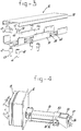
- Figure 4 shows an embodiment wherein a connector 53 comprises a sleeve 54 around the second end 26 of the first cable guide conduit 13.
- the coupling member 55 of the connector 53 comprises a plate 56, transverse to the length direction of the cable guide conduit 13.
- Coupling elements 57 are located in the transverse plate 56 such that the connector 53 can be fixed to an end face of a machine part such as the manifold 2 shown in figure 1.
- Figure 5 shows an embodiment of a connector wherein the second end 26 of the cable guide conduit 13 is connected to a first segment 61 of the connector 60.
- the first segment 61 comprises a first plate 62 having two pins 63,64 projecting perpendicularly from the plate 62.
- a second segment 65 of the connector 60 comprises a plate 66 having two slots 67,68 located on a circular track.
- the second segment 65 is connected via coupling elements 69,70 to the manifold 2.
- the angle ⁇ between the cable guide conduit 13 and the manifold 2 can be varied between 0 degrees and 90 degrees.
- screws are provided for tightening the plate 66 against the plate 62 and for fixing the relative angular positions of the cable guide conduit 13 and the manifold 2.
- figure 6 shows a connector 72 having two similarly shaped segments 73,74.
- both segments 73,74 comprise a sleeve 75,75' in which end parts of a first and a second cable guide conduit 13, 13' are received respectively.
- the relative angle ⁇ between the cable guide conduits 13 and 13' can be varied.
Landscapes
- Engineering & Computer Science (AREA)
- Manufacturing & Machinery (AREA)
- Mechanical Engineering (AREA)
- Injection Moulding Of Plastics Or The Like (AREA)
- Moulds For Moulding Plastics Or The Like (AREA)
- Details Of Connecting Devices For Male And Female Coupling (AREA)
Priority Applications (5)
| Application Number | Priority Date | Filing Date | Title |
|---|---|---|---|
| DE69804932T DE69804932T2 (de) | 1998-01-28 | 1998-01-28 | Modulares Kabelführungssystem |
| EP98200249A EP0933184B1 (de) | 1998-01-28 | 1998-01-28 | Modulares Kabelführungssystem |
| CA002260515A CA2260515A1 (en) | 1998-01-28 | 1999-01-28 | Modular cable guide system |
| BR9917592-4A BR9917592A (pt) | 1998-01-28 | 1999-01-28 | Sistema de guia a cabo modular |
| US09/238,427 US6252168B1 (en) | 1998-01-28 | 1999-01-28 | Modular cable guide system |
Applications Claiming Priority (1)
| Application Number | Priority Date | Filing Date | Title |
|---|---|---|---|
| EP98200249A EP0933184B1 (de) | 1998-01-28 | 1998-01-28 | Modulares Kabelführungssystem |
Publications (2)
| Publication Number | Publication Date |
|---|---|
| EP0933184A1 true EP0933184A1 (de) | 1999-08-04 |
| EP0933184B1 EP0933184B1 (de) | 2002-04-17 |
Family
ID=8233334
Family Applications (1)
| Application Number | Title | Priority Date | Filing Date |
|---|---|---|---|
| EP98200249A Expired - Lifetime EP0933184B1 (de) | 1998-01-28 | 1998-01-28 | Modulares Kabelführungssystem |
Country Status (5)
| Country | Link |
|---|---|
| US (1) | US6252168B1 (de) |
| EP (1) | EP0933184B1 (de) |
| BR (1) | BR9917592A (de) |
| CA (1) | CA2260515A1 (de) |
| DE (1) | DE69804932T2 (de) |
Families Citing this family (2)
| Publication number | Priority date | Publication date | Assignee | Title |
|---|---|---|---|---|
| US20110197947A1 (en) | 2008-03-20 | 2011-08-18 | Miasole | Wire network for interconnecting photovoltaic cells |
| ES2983350T3 (es) | 2017-01-18 | 2024-10-22 | Siemens Gamesa Renewable Energy As | Turbina eólica y método correspondiente |
Citations (2)
| Publication number | Priority date | Publication date | Assignee | Title |
|---|---|---|---|---|
| EP0468485A2 (de) * | 1990-07-27 | 1992-01-29 | Mold-Masters Limited | Vorverdrahteter Spritzgiesszusammenbau |
| GB2250564A (en) * | 1990-10-12 | 1992-06-10 | Rich Muller Limited | Fishplate |
Family Cites Families (3)
| Publication number | Priority date | Publication date | Assignee | Title |
|---|---|---|---|---|
| US4866215A (en) * | 1988-06-06 | 1989-09-12 | Hayes Microcomputer Products, Inc. | Cable management system for equipment enclosure |
| DE4204187C2 (de) * | 1992-02-13 | 1993-12-02 | Raymond A Gmbh & Co Kg | Kabelkanal zur Aufnahme von Kabelbündel |
| US5792993A (en) * | 1997-04-07 | 1998-08-11 | Sigma-Aldrich Company | Wireway sealing device |
-
1998
- 1998-01-28 DE DE69804932T patent/DE69804932T2/de not_active Expired - Fee Related
- 1998-01-28 EP EP98200249A patent/EP0933184B1/de not_active Expired - Lifetime
-
1999
- 1999-01-28 CA CA002260515A patent/CA2260515A1/en not_active Abandoned
- 1999-01-28 BR BR9917592-4A patent/BR9917592A/pt not_active Application Discontinuation
- 1999-01-28 US US09/238,427 patent/US6252168B1/en not_active Expired - Fee Related
Patent Citations (2)
| Publication number | Priority date | Publication date | Assignee | Title |
|---|---|---|---|---|
| EP0468485A2 (de) * | 1990-07-27 | 1992-01-29 | Mold-Masters Limited | Vorverdrahteter Spritzgiesszusammenbau |
| GB2250564A (en) * | 1990-10-12 | 1992-06-10 | Rich Muller Limited | Fishplate |
Also Published As
| Publication number | Publication date |
|---|---|
| DE69804932T2 (de) | 2002-11-07 |
| US6252168B1 (en) | 2001-06-26 |
| DE69804932D1 (de) | 2002-05-23 |
| EP0933184B1 (de) | 2002-04-17 |
| BR9917592A (pt) | 2002-07-30 |
| CA2260515A1 (en) | 1999-07-28 |
Similar Documents
| Publication | Publication Date | Title |
|---|---|---|
| US5269677A (en) | Hot passage manifold system | |
| US5261806A (en) | Electrically heated mold insert | |
| TWI878219B (zh) | 用於保持電纜線的設備 | |
| EP0743159B1 (de) | Spritzgiessvorrichtung mit seitlichem Anschnitt mit radial montierten Anschnitteinsätzen | |
| JP4046807B2 (ja) | 射出成形装置 | |
| US5326251A (en) | Heated injection molding nozzle with alternate thermocouple bores | |
| JP4245674B2 (ja) | 射出成形装置 | |
| US6252168B1 (en) | Modular cable guide system | |
| EP0879689B1 (de) | Verbindungsbuchse für Spritzgiessverteiler | |
| EP1117520B1 (de) | In einen montagekörper einschraubbare spritzgiessdüse | |
| US5720995A (en) | Injection molding manifolds with melt connector bushing | |
| US5334006A (en) | Hot sprue bushing with interchangeable tip having multiple edge gates | |
| EP0695617B1 (de) | Heizbare Spritzgiessdüse mit Schützrohren | |
| EP0468485B1 (de) | Vorverdrahteter Spritzgiesszusammenbau | |
| ATE231431T1 (de) | Vier beheizte düseverteiler miteinander verbunden in einer gemeinsamen fläche | |
| EP0638406B1 (de) | Spritzgiessdüse mit einem Thermoelement | |
| US5474440A (en) | Injection molding nozzle with collar having locating and retaining lug protions | |
| US4774906A (en) | Automatic plastics coating device for elongated bamboo poles | |
| EP0657269B1 (de) | Spritzgiessvorrichtung mit senkrechten Anschnitten mit heisser Spitze | |
| EP0960713B1 (de) | Spritzgiessvorrichtung mit Düsen, die langgestreckte Befestigungsflanschen aufweisen | |
| EP1934034A1 (de) | Verteilanordnung für eine spritzgiessmaschine | |
| EP0695618B1 (de) | Sprizgiessdüse mit Kragen der Positionierungs- und Haltenockenteile aufweist | |
| CA2062903C (en) | Hot passage manifold system | |
| EP0654339B1 (de) | Beheizte Spritzgiessdüse mit alternativen Bohrungen für Thermoelement | |
| CA1262024A (en) | Manifold assembly for plastic injection molding |
Legal Events
| Date | Code | Title | Description |
|---|---|---|---|
| PUAI | Public reference made under article 153(3) epc to a published international application that has entered the european phase |
Free format text: ORIGINAL CODE: 0009012 |
|
| AK | Designated contracting states |
Kind code of ref document: A1 Designated state(s): DE FR GB NL |
|
| AX | Request for extension of the european patent |
Free format text: AL;LT;LV;MK;RO;SI |
|
| 17P | Request for examination filed |
Effective date: 20000127 |
|
| AKX | Designation fees paid |
Free format text: DE FR GB NL |
|
| 17Q | First examination report despatched |
Effective date: 20000922 |
|
| GRAG | Despatch of communication of intention to grant |
Free format text: ORIGINAL CODE: EPIDOS AGRA |
|
| GRAG | Despatch of communication of intention to grant |
Free format text: ORIGINAL CODE: EPIDOS AGRA |
|
| GRAH | Despatch of communication of intention to grant a patent |
Free format text: ORIGINAL CODE: EPIDOS IGRA |
|
| REG | Reference to a national code |
Ref country code: GB Ref legal event code: IF02 |
|
| GRAH | Despatch of communication of intention to grant a patent |
Free format text: ORIGINAL CODE: EPIDOS IGRA |
|
| GRAA | (expected) grant |
Free format text: ORIGINAL CODE: 0009210 |
|
| AK | Designated contracting states |
Kind code of ref document: B1 Designated state(s): DE FR GB NL |
|
| PG25 | Lapsed in a contracting state [announced via postgrant information from national office to epo] |
Ref country code: NL Free format text: LAPSE BECAUSE OF FAILURE TO SUBMIT A TRANSLATION OF THE DESCRIPTION OR TO PAY THE FEE WITHIN THE PRESCRIBED TIME-LIMIT Effective date: 20020417 |
|
| REF | Corresponds to: |
Ref document number: 69804932 Country of ref document: DE Date of ref document: 20020523 |
|
| RAP2 | Party data changed (patent owner data changed or rights of a patent transferred) |
Owner name: SYNVENTIVE HOLDING B.V. |
|
| NLT2 | Nl: modifications (of names), taken from the european patent patent bulletin |
Owner name: SYNVENTIVE HOLDING B.V. |
|
| ET | Fr: translation filed | ||
| NLV1 | Nl: lapsed or annulled due to failure to fulfill the requirements of art. 29p and 29m of the patents act | ||
| PLBE | No opposition filed within time limit |
Free format text: ORIGINAL CODE: 0009261 |
|
| STAA | Information on the status of an ep patent application or granted ep patent |
Free format text: STATUS: NO OPPOSITION FILED WITHIN TIME LIMIT |
|
| REG | Reference to a national code |
Ref country code: FR Ref legal event code: TP Ref country code: FR Ref legal event code: CD |
|
| 26N | No opposition filed |
Effective date: 20030120 |
|
| PGFP | Annual fee paid to national office [announced via postgrant information from national office to epo] |
Ref country code: DE Payment date: 20060127 Year of fee payment: 9 Ref country code: FR Payment date: 20060127 Year of fee payment: 9 |
|
| PG25 | Lapsed in a contracting state [announced via postgrant information from national office to epo] |
Ref country code: DE Free format text: LAPSE BECAUSE OF NON-PAYMENT OF DUE FEES Effective date: 20070801 |
|
| GBPC | Gb: european patent ceased through non-payment of renewal fee |
Effective date: 20070128 |
|
| REG | Reference to a national code |
Ref country code: FR Ref legal event code: ST Effective date: 20070930 |
|
| PG25 | Lapsed in a contracting state [announced via postgrant information from national office to epo] |
Ref country code: GB Free format text: LAPSE BECAUSE OF NON-PAYMENT OF DUE FEES Effective date: 20070128 |
|
| PG25 | Lapsed in a contracting state [announced via postgrant information from national office to epo] |
Ref country code: FR Free format text: LAPSE BECAUSE OF NON-PAYMENT OF DUE FEES Effective date: 20070131 |
|
| PGFP | Annual fee paid to national office [announced via postgrant information from national office to epo] |
Ref country code: GB Payment date: 20060131 Year of fee payment: 9 |