EP0933254B1 - Zwischenstück zum Reflektoreinbau auf ein Auflagelement eines Scheinwerfers - Google Patents
Zwischenstück zum Reflektoreinbau auf ein Auflagelement eines Scheinwerfers Download PDFInfo
- Publication number
- EP0933254B1 EP0933254B1 EP19990400196 EP99400196A EP0933254B1 EP 0933254 B1 EP0933254 B1 EP 0933254B1 EP 19990400196 EP19990400196 EP 19990400196 EP 99400196 A EP99400196 A EP 99400196A EP 0933254 B1 EP0933254 B1 EP 0933254B1
- Authority
- EP
- European Patent Office
- Prior art keywords
- mounting
- washer
- reflector
- fixing element
- intermediate fixing
- Prior art date
- Legal status (The legal status is an assumption and is not a legal conclusion. Google has not performed a legal analysis and makes no representation as to the accuracy of the status listed.)
- Expired - Lifetime
Links
- 230000002093 peripheral effect Effects 0.000 claims description 24
- 239000002184 metal Substances 0.000 claims description 2
- 239000012815 thermoplastic material Substances 0.000 claims description 2
- 238000000605 extraction Methods 0.000 description 2
- 230000014759 maintenance of location Effects 0.000 description 2
- 238000004873 anchoring Methods 0.000 description 1
- 238000005452 bending Methods 0.000 description 1
- 230000000295 complement effect Effects 0.000 description 1
- 230000006866 deterioration Effects 0.000 description 1
- 230000000694 effects Effects 0.000 description 1
- 238000004519 manufacturing process Methods 0.000 description 1
Images

Classifications
-
- F—MECHANICAL ENGINEERING; LIGHTING; HEATING; WEAPONS; BLASTING
- F16—ENGINEERING ELEMENTS AND UNITS; GENERAL MEASURES FOR PRODUCING AND MAINTAINING EFFECTIVE FUNCTIONING OF MACHINES OR INSTALLATIONS; THERMAL INSULATION IN GENERAL
- F16B—DEVICES FOR FASTENING OR SECURING CONSTRUCTIONAL ELEMENTS OR MACHINE PARTS TOGETHER, e.g. NAILS, BOLTS, CIRCLIPS, CLAMPS, CLIPS OR WEDGES; JOINTS OR JOINTING
- F16B21/00—Means for preventing relative axial movement of a pin, spigot, shaft or the like and a member surrounding it; Stud-and-socket releasable fastenings
- F16B21/06—Releasable fastening devices with snap-action
- F16B21/08—Releasable fastening devices with snap-action in which the stud, pin, or spigot has a resilient part
- F16B21/084—Releasable fastening devices with snap-action in which the stud, pin, or spigot has a resilient part with a series of flexible ribs or fins extending laterally from the shank of the stud, pin or spigot, said ribs or fins deforming predominantly in a direction parallel to the direction of insertion of the shank
-
- B—PERFORMING OPERATIONS; TRANSPORTING
- B60—VEHICLES IN GENERAL
- B60Q—ARRANGEMENT OF SIGNALLING OR LIGHTING DEVICES, THE MOUNTING OR SUPPORTING THEREOF OR CIRCUITS THEREFOR, FOR VEHICLES IN GENERAL
- B60Q1/00—Arrangement of optical signalling or lighting devices, the mounting or supporting thereof or circuits therefor
- B60Q1/02—Arrangement of optical signalling or lighting devices, the mounting or supporting thereof or circuits therefor the devices being primarily intended to illuminate the way ahead or to illuminate other areas of way or environments
- B60Q1/04—Arrangement of optical signalling or lighting devices, the mounting or supporting thereof or circuits therefor the devices being primarily intended to illuminate the way ahead or to illuminate other areas of way or environments the devices being headlights
- B60Q1/06—Arrangement of optical signalling or lighting devices, the mounting or supporting thereof or circuits therefor the devices being primarily intended to illuminate the way ahead or to illuminate other areas of way or environments the devices being headlights adjustable, e.g. remotely-controlled from inside vehicle
- B60Q1/068—Arrangement of optical signalling or lighting devices, the mounting or supporting thereof or circuits therefor the devices being primarily intended to illuminate the way ahead or to illuminate other areas of way or environments the devices being headlights adjustable, e.g. remotely-controlled from inside vehicle by mechanical means
- B60Q1/0683—Adjustable by rotation of a screw
-
- B—PERFORMING OPERATIONS; TRANSPORTING
- B60—VEHICLES IN GENERAL
- B60Q—ARRANGEMENT OF SIGNALLING OR LIGHTING DEVICES, THE MOUNTING OR SUPPORTING THEREOF OR CIRCUITS THEREFOR, FOR VEHICLES IN GENERAL
- B60Q2200/00—Special features or arrangements of vehicle headlamps
- B60Q2200/30—Special arrangements for adjusting headlamps, e.g. means for transmitting the movements for adjusting the lamps
- B60Q2200/32—Ball-joints
Definitions
- the present invention relates generally to the mounting of a reflector on a bearing part of a motor vehicle headlamp.
- a motor vehicle headlamp comprising a reflector mounted on a support part by means of a intermediate fastening element having a first end capable of cooperating with said support part and a second end capable of cooperating with a mounting part of the reflector in a mounting / dismounting direction X.
- the invention also relates to an intermediate fixing element for such an arrangement.
- said turret mounting includes a specific arrangement, of the spherical housing type shape complementary to that of said spherical head.
- This mounting sleeve has a mounting tab that extends according to the direction of assembly / disassembly of said socket in the turret mounting the reflector.
- the mounting tab has a tooth at its end latching intended to snap onto the outer wall of said turret mounting when engaging the mounting sleeve in said turret according to said assembly / disassembly direction.
- a lighting device for motor vehicle which comprises a reflector provided on its rear part with a mounting part able to cooperate with an intermediate fixing element of which one end is mounted on a support part of the projector and a second end cooperates with said mounting part of the reflector.
- This intermediate fastening element comprises on the one hand a first element which engages inside the mounting part and whose external surface cooperates by friction with the internal smooth wall of the mounting part of the reflector, and on the other hand, a second tubular element which covers the external part of the reflector mounting wall and which is snap connected to the first element of the intermediate fixing element.
- the present invention provides a new motor vehicle headlight of the aforementioned type in introduction, in which the system for mounting the reflector on a support part of the projector is particularly simple and economical.
- a washer is provided mounted on the second end of said fixing element intermediate so that it generally extends substantially transverse to said mounting / dismounting direction X, and which has an edge device intended to be anchored in a smooth surface of said part of mounting of the reflector, for retaining said intermediate fixing element on said mounting part of the reflector.
- the washer may have an edge rectangular or circular device with a sharp, flat or bevelled profile or still a sawtooth profile.
- the washer provided in the headlight according to the invention may have a flat profile or be slightly curved according to a funnel-shaped profile.
- the second end of the intermediate fastener has fins elastically deformable generally extending substantially transverse to said mounting / dismounting direction X and being able to come in taken with the smooth surface of said reflector mounting part, being deforming to frictionally retain said intermediate fastening element on said mounting part of the reflector.
- each elastically deformable fin can be present in the form of a ring delimited on the one hand, by an upper surface facing towards said support part, extending transversely to said direction of assembly / disassembly X, and on the other hand by a lower surface facing the reflector, extending in an oblique direction Y to said direction of mounting / dismounting X in a direction opposite to the mounting direction F1 of said intermediate fixing element on said reflector mounting part in direction of said smooth wall.
- the intermediate fastening element comprises a cylindrical body provided on its outer surface of a groove for mounting the washer which includes effect, a central opening open on the peripheral edge by a flared part, said washer being intended to be mounted on the body of the fixing element intermediate by blistering with a passage from a hard point at the connection between the flared part and the central orifice of said washer.
- the body of the fixing element intermediate can be provided on its outer surface with said fins elastically deformable, said body being capable of being engaged in the direction mounting / dismounting X inside a blind hole with smooth wall of said part mounting the reflector, so that said fins engage said smooth wall of the blind hole, deforming to tilt in one direction oblique to said mounting direction in a direction opposite to the direction of engagement F1 of said body in said blind hole, and the peripheral edge of the washer is anchored in the smooth wall of the blind hole, said washer inclining according to a direction oblique to the direction of assembly / disassembly X according to a opposite direction to the direction of engagement F1 of said body in said blind hole.
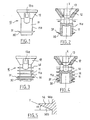
- FIGS 1 to 4 there are shown two embodiments of a intermediate fastening element 10 intended in particular for mounting a reflector (not shown) on a support part of a motor vehicle headlamp (not represented).
- This intermediate fastening element 10 extends in a direction general X which is the direction of assembly / disassembly of said fixing element intermediate on a mounting part 20 of the reflector (not shown).
- It has a first end 12 able to cooperate with said part support (not shown) of the projector.
- support part is meant, for example an adjustment rod mounted at translation on a fixed part (not shown) of the projector such as a housing headlamp or part of the body, or for example a mounting rod fixed on a fixed part of a projector.
- the first end 12 of said element of intermediate fixing 10 comprises a housing 13 which generally extends in the direction of assembly / disassembly X of said intermediate fastening element and which has an opening towards the outside.
- the side walls of said housing 13 are provided with cutouts forming elastic tabs 13a (see FIGS. 1 and 3) for the blistering of the housing 13 of the end 12 on the end sphere of a projector adjustment or mounting rod.
- the intermediate fastening element 10 shown in Figures 1 at 4 has a second end 11 formed here by a cylindrical body recess 11 extending in the direction of assembly / disassembly X.
- a washer 30 mounted on the body 11 of said intermediate element 10 so that it extends generally substantially transversely to said direction of assembly / disassembly X.
- This washer 30 has a peripheral edge 31 which as shown in Figure 11 is intended to be anchored in a smooth surface 21 of the mounting part 20 of the reflector for retaining said fixing element intermediate 10 on said mounting part 20 of the reflector.
- the cylindrical body 11 is provided on its outer surface 11a with a groove, and the washer 30 for this purpose comprises a central orifice 32 (see FIGS. 6 to 9) open on the peripheral edge 31 by a flared part 33, said washer 30 can be mounted on the body 11 of the intermediate fastening element 10 by blistering with a passage of a hard point at the connection between the part flared 33 and the central hole 32 of the washer 30.
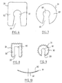
- FIGS 6 to 9 show different embodiments of the washer 30.
- the washer 30 has a rectangular peripheral edge 31 with rounded corners.
- the central opening 32 of the washer 30 is a circular orifice which opens on the peripheral edge 31 by a flared part 33 with straight edges.
- the washer 30 has a circular peripheral edge 31 so that it is shaped in shape ring, with a circular central hole 32 which opens through the flared part 33 on the peripheral edge 31.
- the peripheral edge 31 of the washer 30 has a sharp or bevelled sharp profile.
- the central orifice 32 of the washer has a rectangular shape which opens on the peripheral edge by a part slightly flared 33 with straight edges.
- the peripheral edge 31 of the washer 30 follows a circular path with a sawtooth profile.
- the central opening 32 of this washer 30 is circular and opens on the edge peripheral 31 by a flared portion 33 with straight edges.
- the washer 30 may have a flat profile or as shown in the Figure 10, be slightly curved according to a funnel-shaped profile.
- the intermediate fastener 10 shown in Figures 1 and 2 comprises a cylindrical body 11 whose outer surface 11a is smooth and it is the washer 30 mounted on the cylindrical body 11 which is intended as has been previously mentioned to retain the intermediate fixing element on the part mounting, anchoring in the smooth surface 21 of the mounting portion 20 of the reflector.
- the intermediate fixing element 10 shown in FIGS. 3 and 4 has a hollow cylindrical body 11 which is provided on its outer surface 11a a plurality of elastically deformable fins 14.
- These fins 14 are distributed regularly over the length of said body 11.
- the fins 14 generally extend substantially transverse to the mounting / dismounting direction X and are suitable (see more particularly Figures 11 and 12 described later), to engage with a smooth surface 21 of the mounting part 20 of the reflector, being deformed to retain by friction, the intermediate fixing element on the mounting part 20.
- the retention of the fixing element intermediate 10 on the mounting part 20 of the reflector is obtained by the action combined washer 30 and fins 14.
- Each fin 14 is in the form of a ring surrounding said body.
- this ring is delimited by an upper surface 14a facing the support part and a surface lower 14b facing the reflector.
- each ring 14 extends transversely to said assembly / disassembly direction X and the lower surface 14b extends in a oblique direction Y to the assembly / disassembly direction X in an opposite direction in the direction of assembly F1 (see FIG. 11) of said intermediate fixing element 10 on the mounting part 20 of the reflector, in the direction of said smooth surface 21.
- each fin 14 forms an angle ⁇ with the direction transverse to the assembly / disassembly direction X.
- This angle ⁇ has a value of the order of 7 degrees.
- the washer 30 is made of thin and flexible sheet metal.
- the fastening element intermediate 10 is made of a thermoplastic material having a certain elasticity.
- the body 11 of the fastener intermediate 10 is engaged inside a blind hole 22 of a part of mounting 20 of a reflector (not shown), and like this provided with fins and of the washer, has an outside diameter greater than the inside diameter of the blind hole 22, the elastically deformable fins 14 engage with the smooth surface 21 of the blind hole 22, deforming so as to tilt according to a more accentuated direction than the oblique direction Y of departure compared to the assembly / disassembly direction X in a direction opposite to the assembly direction or of engagement F1 of said body 11 in the blind hole 22.
- the washer 30 which here has a funnel profile, comes also tilt in a slightly more accentuated oblique direction than the oblique direction of departure of the funnel, in relation to the direction of mounting / dismounting X in a direction opposite to the mounting direction or of engagement F1 of the body 11 in said blind hole 22, and its peripheral edge 31 is anchored in the smooth wall 21 of the blind hole 22.
- the mounting part 20 has an end edge 23 flared towards outside.
- the fins 14 thus make it possible to retain said friction element by friction.
- the washer 30 in the peripheral edge 31 is anchored in the smooth wall 21 of the blind hole 22 and reinforces the retention of the intermediate fastening element 10 on the mounting part 20.
- the washer 30 in the peripheral edge 31 is anchored in the smooth wall 21 of the blind hole 22, also arises the extraction movement towards the outside in the direction F2 of said intermediate fixing element 10.
- the assembly of the reflector of said intermediate fixing element is then cannot be dismantled, since the dismantling of the intermediate fixing element cannot produce without causing the rupture of the fins and / or the washer, and deterioration of said intermediate fixing element.
Landscapes
- Engineering & Computer Science (AREA)
- General Engineering & Computer Science (AREA)
- Mechanical Engineering (AREA)
- Non-Portable Lighting Devices Or Systems Thereof (AREA)
- Transition And Organic Metals Composition Catalysts For Addition Polymerization (AREA)
- Lighting Device Outwards From Vehicle And Optical Signal (AREA)
Claims (19)
- Kraftfahrzeugscheinwerfer mit einem Reflektor, der an einem Auflageteil mit Hilfe eines Befestigungszwischenstücks (10) angebracht ist, das ein erstes Ende (12) aufweist, das mit dem Auflageteil zusammenzuwirken vermag, sowie ein zweites Ende (11), das mit einem Montageteil (20) des Reflektors in einer Montage- bzw. Demontagerichtung X zusammenzuwirken vermag, dadurch gekennzeichnet, daß eine Unterlegscheibe (30) vorgesehen ist, die am zweiten Ende (11) des Befestigungszwischenstücks (10) so angebracht ist, daß sie sich allgemein im wesentlichen quer zur Montage- bzw. Demontagerichtung X erstreckt, und die einen Umfangsrand (31) aufweist, der dazu bestimmt ist, sich in einer glatten Oberfläche (21) des Montageteils (20) des Reflektors zu verankern, um dieses Befestigungszwischenstück (10) auf dem Montageteil des Reflektors zu halten.
- Scheinwerfer nach Anspruch 1,
dadurch gekennzeichnet, daß die Unterlegscheibe (30) einen rechteckigen Umfangsrand (31) aufweist. - Scheinwerfer nach Anspruch 1,
dadurch gekennzeichnet, daß die Unterlegscheibe (30) einen kreisförmigen Umfangsrand (31) aufweist. - Scheinwerfer nach einem der Ansprüche 1 bis 3,
dadurch gekennzeichnet, daß der Umfangsrand (31) der Unterlegscheibe (30) ein flaches oder abgekantetes geschliffenes Profil aufweist. - Scheinwerfer nach einem der Ansprüche 1 bis 3,
dadurch gekennzeichnet, daß der Umfangsrand (31). der Unterlegscheibe (30) ein sägezahnförmiges Profil aufweist. - Scheinwerfer nach einem der Ansprüche 1 bis 5,
dadurch gekennzeichnet, daß das Befestigungszwischenstück (10) einen zylindrischen Körper (11) umfaßt, der an seiner Außenseite (11a) mit einer Nut zur Anbringung der Unterlegscheibe (30) versehen ist, die zu diesem Zweck eine mittige öffnung (32) aufweist, welche am Umfangsrand (31) durch eine konisch erweiterte Ausnehmung (33) geöffnet ist, wobei die Unterlegscheibe (30) dazu bestimmt ist, an dem Körper (11) des Befestigungszwischenstücks (10) durch Einrasten angebracht zu werden und hierbei eine harte Stelle am Übergang zwischen der konisch erweiterten Ausnehmung (33) und der mittigen Öffnung (32) der Unterlegscheibe (30) passiert wird. - Scheinwerfer nach einem der Ansprüche 1 bis 6,
dadurch gekennzeichnet, daß die Unterlegscheibe (30) ein ebenes Profil aufweist. - Scheinwerfer nach einem der Ansprüche 1 bis 6,
dadurch gekennzeichnet, daß die Unterlegscheibe (30) leicht trichterförmig gebogen ist. - Scheinwerfer nach einem der vorhergehenden Ansprüche,
dadurch gekennzeichnet, daß das zweite Ende (11) des Befestigungszwischenstücks (10) elastisch verformbare Rippen (14) aufweist, die sich allgemein im wesentlichen quer zur Montage- bzw. Demontagerichtung X erstrecken und mit der glatten Oberfläche (21) des Montageteils (20) des Reflektors unter Verformung in Eingriff kommen können, um das Befestigungszwischenstück (10) an dem Montageteil (20) des Reflektors durch Reibung zu halten. - Scheinwerfer nach Anspruch 9,
dadurch gekennzeichnet, daß jede elastisch verformbare Rippe (14) die Form eines Rings aufweist, der einerseits durch eine dem Auflageteil zugewandte Oberseite (14a), die sich quer zur Montage- bzw. Demontagerichtung X erstreckt, und andererseits durch eine dem Reflektor zugewandte Unterseite (14b) begrenzt ist, die sich entgegengesetzt zur Montagerichtung F1 des Befestigungszwischenstücks (10) an dem Montageteil (20) des Reflektors in einer schräg zur Montage- bzw. Demontagerichtung X verlaufenden Richtung Y in Richtung der glatten Oberfläche (21) erstreckt. - Scheinwerfer nach Anspruch 10,
dadurch gekennzeichnet, daß die Unterseite (14b) jeder Rippe (14) einen Winkel α von etwa 7 Grad mit der quer zur Montage- bzw. Demontagerichtung X verlaufenden Richtung bildet. - Scheinwerfer nach einem der Ansprüche 6 bis 11,
dadurch gekennzeichnet, daß der Körper (11) des Befestigungszwischenstücks (10) an seiner Außenseite (11a) mit diesen elastisch verformbaren Rippen (14) versehen ist, wobei der Körper (11) in Montage- bzw. Demontagerichtung X innen in ein Sackloch (22) mit glatter Wandung (21) des Montageteils (20) des Reflektors eingeführt zu werden vermag, so daß die Rippen (14) in Eingriff mit dieser glatten Wandung (21) des Sacklochs (22) kommen und sich dabei verformen, um sich in bezug auf die Montagerichtung (10) in einer Richtung schräg zu stellen, die der Einführungsrichtung F1 des Körpers (11) in das Sackloch (22) entgegengesetzt ist, und sich der Umfangsrand (31) der Unterlegscheibe (30) in der glatten Wand des Sacklochs (22) verankert, wobei sich die Unterlegscheibe (30) in bezug auf die Montage- bzw. Demontagerichtung X in eine Richtung schräg stellt, die der Einführungsrichtung F1 des Körpers (11) in das Sackloch (22) entgegengesetzt ist. - Scheinwerfer nach Anspruch 12,
dadurch gekennzeichnet, daß das Montageteil (20) am Ende einen nach außen konisch erweiterten Rand (23) umfaßt, um das Einführen des Befestigungszwischenstücks (10) in das Sackloch (22) zu erleichtern. - Scheinwerfer nach einem der Ansprüche 1 bis 13,
dadurch gekennzeichnet, daß das erste Ende (12) des Befestigungszwischenstücks (10) so ausgebildet ist, daß es auf das Ende einer Einstellstange aufgesetzt werden kann, die in einem feststehenden Teil des Scheinwerfers translatorisch verstellbar angebracht ist. - Scheinwerfer nach einem der Ansprüche 1 bis 13,
dadurch gekennzeichnet, daß das erste Ende (12) des Befestigungszwischenstücks (10) so ausgebildet ist, daß es auf das Ende einer Montagestange aufgesetzt werden kann, die an einem feststehenden Teil des Scheinwerfers befestigt ist. - Scheinwerfer nach einem der Ansprüche 1 bis 15,
dadurch gekennzeichnet, daß das Befestigungszwischenstück (10) aus einem thermoplastischen Material mit geringer Elastizität ausgeführt ist. - Scheinwerfer nach einem der Ansprüche 1 bis 16,
dadurch gekennzeichnet, daß die Unterlegscheibe (30) aus biegsamem Feinblech ausgeführt ist. - Befestigungszwischenstück (10), das zur Montage eines Reflektors an einem Auflageteil eines Kraftfahrzeugscheinwerfers bestimmt ist und ein erstes Ende (12) aufweist, das mit dem Auflageteil zusammenzuwirken vermag, sowie ein zweites Ende (11), das mit einem Montageteil (20) des Reflektors in einer Montage- bzw. Demontagerichtung zusammenzuwirken vermag, dadurch gekennzeichnet, daß es an seinem zweiten Ende (11) eine Unterlegscheibe (30) trägt, die sich allgemein nahezu senkrecht zur Montage- bzw. Demontagerichtung (X) erstreckt und einen Umfangsrand (31) aufweist, der dazu bestimmt ist, sich in einer glatten Oberfläche (21) des Montageteils (20) des Reflektors zu verankern, um dieses Befestigungszwischenstück (10) an dem Montageteil (20) zu halten.
- Befestigungszwischenstück nach Anspruch 18,
dadurch gekennzeichnet, daß es elastisch verformbare Rippen (14) umfaßt, die sich allgemein im wesentlichen quer zur Montage- bzw. Demontagerichtung (X) erstrecken und unter Verformung mit der glatten Oberfläche (21) des Montageteils (20) des Reflektors in Eingriff kommen können, um das Befestigungszwischenstück an dem Montageteil (20) durch Reibung zu halten.
Applications Claiming Priority (2)
| Application Number | Priority Date | Filing Date | Title |
|---|---|---|---|
| FR9801054 | 1998-01-30 | ||
| FR9801054A FR2774337B1 (fr) | 1998-01-30 | 1998-01-30 | Element de fixation intermediaire pour le montage d'un reflecteur sur une partie d'appui d'un projecteur |
Publications (2)
| Publication Number | Publication Date |
|---|---|
| EP0933254A1 EP0933254A1 (de) | 1999-08-04 |
| EP0933254B1 true EP0933254B1 (de) | 2002-08-14 |
Family
ID=9522379
Family Applications (1)
| Application Number | Title | Priority Date | Filing Date |
|---|---|---|---|
| EP19990400196 Expired - Lifetime EP0933254B1 (de) | 1998-01-30 | 1999-01-28 | Zwischenstück zum Reflektoreinbau auf ein Auflagelement eines Scheinwerfers |
Country Status (5)
| Country | Link |
|---|---|
| EP (1) | EP0933254B1 (de) |
| BR (1) | BR9900180A (de) |
| DE (1) | DE69902489C5 (de) |
| ES (1) | ES2181368T3 (de) |
| FR (1) | FR2774337B1 (de) |
Family Cites Families (6)
| Publication number | Priority date | Publication date | Assignee | Title |
|---|---|---|---|---|
| FR2547369B1 (fr) * | 1983-06-09 | 1986-10-24 | Morin Jacques | Dispositif de fixation murale |
| DE3543563C1 (de) * | 1985-12-10 | 1987-05-07 | Hella Kg Hueck & Co | Fahrzeugscheinwerfer |
| EP0464690A1 (de) * | 1990-06-29 | 1992-01-08 | CARELLO S.p.A. | Verstellbarer Reflektor, insbesondere für Fahrzeugscheinwerfer |
| JPH06151171A (ja) | 1992-11-02 | 1994-05-31 | Matsushita Electric Ind Co Ltd | 軟磁性薄膜体とその製造方法およびそれを用いた磁気ヘッド |
| IT1257139B (it) * | 1992-11-03 | 1996-01-05 | Carello Spa | Proiettore, particolarmente per veicoli. |
| FR2752040B1 (fr) * | 1996-07-31 | 1998-10-30 | Valeo Vision | Element de fixation intermediaire pour le montage d'un reflecteur sur une partie d'appui d'un projecteur |
-
1998
- 1998-01-30 FR FR9801054A patent/FR2774337B1/fr not_active Expired - Lifetime
-
1999
- 1999-01-27 BR BR9900180-2A patent/BR9900180A/pt not_active IP Right Cessation
- 1999-01-28 EP EP19990400196 patent/EP0933254B1/de not_active Expired - Lifetime
- 1999-01-28 ES ES99400196T patent/ES2181368T3/es not_active Expired - Lifetime
- 1999-01-28 DE DE69902489.7T patent/DE69902489C5/de not_active Expired - Lifetime
Also Published As
| Publication number | Publication date |
|---|---|
| FR2774337B1 (fr) | 2000-06-16 |
| DE69902489T2 (de) | 2003-06-05 |
| EP0933254A1 (de) | 1999-08-04 |
| DE69902489C5 (de) | 2019-07-11 |
| FR2774337A1 (fr) | 1999-08-06 |
| ES2181368T3 (es) | 2003-02-16 |
| BR9900180A (pt) | 2000-01-18 |
| DE69902489D1 (de) | 2002-09-19 |
Similar Documents
| Publication | Publication Date | Title |
|---|---|---|
| EP0822118B1 (de) | Zwischenstück zum Reflektoreinbau auf ein Auflagelement eines Scheinwerfers | |
| EP2494245B1 (de) | Schnell zu montierende schraubenlose anbringungsklammer | |
| FR3057918A1 (fr) | Dispositif de serrage comprenant un collier de serrage a temoin de positionnement | |
| FR2817930A1 (fr) | Boulon d'ancrage a expansion pour une fixation dans un support, en particulier dans du beton | |
| FR3036312A1 (fr) | Patte de derailleur | |
| EP0933254B1 (de) | Zwischenstück zum Reflektoreinbau auf ein Auflagelement eines Scheinwerfers | |
| EP1813826B1 (de) | Vorrichtung für eine lösbare Verbindung, die eine Verriegelungsklammer umfasst | |
| EP1931235B1 (de) | Öse | |
| EP0549383B1 (de) | Käfig für Drehgelenk | |
| EP1138963A1 (de) | Haltevorrichtung für eine Bowdenzughülle | |
| EP3628877B1 (de) | Käfigmutter-vorrichtung für eine montage auf einem hohlen ständer | |
| FR2492015A1 (fr) | Perfectionnement aux attaches en matiere plastique pour assurer une fixation sur le bord d'une plaque | |
| EP0972675B1 (de) | Zwischenstück zum Elementeinbau auf ein Auflageelement eines Scheinwerfers | |
| FR3047281A1 (fr) | Agrafe demontable de supportage d’un element de garnissage pour vehicule automobile | |
| FR2716710A1 (fr) | Dispositif de fixation d'une source lumineuse dans un support de réception d'un projecteur. | |
| FR2787554A1 (fr) | Element de fixation intermediaire d'un reflecteur sur une partie d'appui d'un projecteur de vehicule automobile, et projecteur comprenant un tel element | |
| EP1409922B1 (de) | Kraftfahrzeugscheinwerfer mit verbesserter elektromagnetischer abschirmung | |
| EP1398209B1 (de) | Anordnung für die Befestigung einer Beleuchtung- oder Signal-Einrichtung auf einem Kfz angeordneten Träger | |
| CH571674A5 (en) | Elongate cylindrical item support mount - has spring tongues at opposite sides and ends snapping over periphery | |
| FR2508121A3 (fr) | Organe de liaison effective entre deux elements de materiaux tendres | |
| FR2945845A1 (fr) | Dispositif de maintien d'ecrou. | |
| WO2024008974A1 (fr) | Pièce de fixation | |
| EP1109687B1 (de) | Steuereinrichtung für kraftfahrzeugausrüstung | |
| FR2902845A1 (fr) | Piece de liaison pour le positionnement d'une patte dans un logement | |
| FR2770005A1 (fr) | Bouton de commande, notamment pour tableau de bord de vehicule automobile |
Legal Events
| Date | Code | Title | Description |
|---|---|---|---|
| PUAI | Public reference made under article 153(3) epc to a published international application that has entered the european phase |
Free format text: ORIGINAL CODE: 0009012 |
|
| AK | Designated contracting states |
Kind code of ref document: A1 Designated state(s): DE ES GB IT |
|
| AX | Request for extension of the european patent |
Free format text: AL;LT;LV;MK;RO;SI |
|
| 17P | Request for examination filed |
Effective date: 20000117 |
|
| AKX | Designation fees paid |
Free format text: DE ES GB IT |
|
| GRAG | Despatch of communication of intention to grant |
Free format text: ORIGINAL CODE: EPIDOS AGRA |
|
| 17Q | First examination report despatched |
Effective date: 20011024 |
|
| GRAG | Despatch of communication of intention to grant |
Free format text: ORIGINAL CODE: EPIDOS AGRA |
|
| GRAH | Despatch of communication of intention to grant a patent |
Free format text: ORIGINAL CODE: EPIDOS IGRA |
|
| GRAG | Despatch of communication of intention to grant |
Free format text: ORIGINAL CODE: EPIDOS AGRA |
|
| GRAH | Despatch of communication of intention to grant a patent |
Free format text: ORIGINAL CODE: EPIDOS IGRA |
|
| GRAH | Despatch of communication of intention to grant a patent |
Free format text: ORIGINAL CODE: EPIDOS IGRA |
|
| GRAA | (expected) grant |
Free format text: ORIGINAL CODE: 0009210 |
|
| AK | Designated contracting states |
Kind code of ref document: B1 Designated state(s): DE ES GB IT |
|
| REG | Reference to a national code |
Ref country code: GB Ref legal event code: FG4D Free format text: NOT ENGLISH |
|
| REF | Corresponds to: |
Ref document number: 69902489 Country of ref document: DE Date of ref document: 20020919 |
|
| GBT | Gb: translation of ep patent filed (gb section 77(6)(a)/1977) |
Effective date: 20021106 |
|
| REG | Reference to a national code |
Ref country code: ES Ref legal event code: FG2A Ref document number: 2181368 Country of ref document: ES Kind code of ref document: T3 |
|
| PLBE | No opposition filed within time limit |
Free format text: ORIGINAL CODE: 0009261 |
|
| STAA | Information on the status of an ep patent application or granted ep patent |
Free format text: STATUS: NO OPPOSITION FILED WITHIN TIME LIMIT |
|
| 26N | No opposition filed |
Effective date: 20030515 |
|
| REG | Reference to a national code |
Ref country code: DE Ref legal event code: R039 Ref document number: 69902489 Country of ref document: DE Ref country code: DE Ref legal event code: R008 Ref document number: 69902489 Country of ref document: DE |
|
| REG | Reference to a national code |
Ref country code: ES Ref legal event code: GD2A Effective date: 20160310 |
|
| PGFP | Annual fee paid to national office [announced via postgrant information from national office to epo] |
Ref country code: DE Payment date: 20180111 Year of fee payment: 20 Ref country code: GB Payment date: 20180117 Year of fee payment: 20 Ref country code: ES Payment date: 20180220 Year of fee payment: 20 |
|
| PGFP | Annual fee paid to national office [announced via postgrant information from national office to epo] |
Ref country code: IT Payment date: 20180115 Year of fee payment: 20 |
|
| REG | Reference to a national code |
Ref country code: DE Ref legal event code: R043 Ref document number: 69902489 Country of ref document: DE |
|
| REG | Reference to a national code |
Ref country code: DE Ref legal event code: R071 Ref document number: 69902489 Country of ref document: DE |
|
| REG | Reference to a national code |
Ref country code: GB Ref legal event code: PE20 Expiry date: 20190127 |
|
| PG25 | Lapsed in a contracting state [announced via postgrant information from national office to epo] |
Ref country code: GB Free format text: LAPSE BECAUSE OF EXPIRATION OF PROTECTION Effective date: 20190127 |
|
| REG | Reference to a national code |
Ref country code: DE Ref legal event code: R206 Ref document number: 69902489 Country of ref document: DE |
|
| REG | Reference to a national code |
Ref country code: ES Ref legal event code: FD2A Effective date: 20220128 |
|
| PG25 | Lapsed in a contracting state [announced via postgrant information from national office to epo] |
Ref country code: ES Free format text: LAPSE BECAUSE OF EXPIRATION OF PROTECTION Effective date: 20190129 |