EP0933271B1 - Frein à main muni d'un dispositif de rattrapage automatique pour véhicules automobiles - Google Patents
Frein à main muni d'un dispositif de rattrapage automatique pour véhicules automobiles Download PDFInfo
- Publication number
- EP0933271B1 EP0933271B1 EP98122531A EP98122531A EP0933271B1 EP 0933271 B1 EP0933271 B1 EP 0933271B1 EP 98122531 A EP98122531 A EP 98122531A EP 98122531 A EP98122531 A EP 98122531A EP 0933271 B1 EP0933271 B1 EP 0933271B1
- Authority
- EP
- European Patent Office
- Prior art keywords
- hand brake
- lever
- spring
- bridge
- type support
- Prior art date
- Legal status (The legal status is an assumption and is not a legal conclusion. Google has not performed a legal analysis and makes no representation as to the accuracy of the status listed.)
- Expired - Lifetime
Links
- 230000008878 coupling Effects 0.000 claims description 15
- 238000010168 coupling process Methods 0.000 claims description 15
- 238000005859 coupling reaction Methods 0.000 claims description 15
- 230000000295 complement effect Effects 0.000 claims description 4
- 239000000463 material Substances 0.000 claims description 3
- 230000005540 biological transmission Effects 0.000 claims 9
- 230000015572 biosynthetic process Effects 0.000 description 4
- 230000000694 effects Effects 0.000 description 3
- 230000006835 compression Effects 0.000 description 2
- 238000007906 compression Methods 0.000 description 2
- 238000010586 diagram Methods 0.000 description 2
- 238000006073 displacement reaction Methods 0.000 description 2
- 238000009826 distribution Methods 0.000 description 2
- 210000000078 claw Anatomy 0.000 description 1
- 239000012141 concentrate Substances 0.000 description 1
- 238000010276 construction Methods 0.000 description 1
- 238000001514 detection method Methods 0.000 description 1
- 238000007373 indentation Methods 0.000 description 1
- 238000004519 manufacturing process Methods 0.000 description 1
- 239000002184 metal Substances 0.000 description 1
- 238000000034 method Methods 0.000 description 1
- 210000000056 organ Anatomy 0.000 description 1
- 238000000926 separation method Methods 0.000 description 1
- 238000003860 storage Methods 0.000 description 1
Images


Classifications
-
- B—PERFORMING OPERATIONS; TRANSPORTING
- B60—VEHICLES IN GENERAL
- B60T—VEHICLE BRAKE CONTROL SYSTEMS OR PARTS THEREOF; BRAKE CONTROL SYSTEMS OR PARTS THEREOF, IN GENERAL; ARRANGEMENT OF BRAKING ELEMENTS ON VEHICLES IN GENERAL; PORTABLE DEVICES FOR PREVENTING UNWANTED MOVEMENT OF VEHICLES; VEHICLE MODIFICATIONS TO FACILITATE COOLING OF BRAKES
- B60T7/00—Brake-action initiating means
- B60T7/02—Brake-action initiating means for personal initiation
- B60T7/08—Brake-action initiating means for personal initiation hand actuated
- B60T7/10—Disposition of hand control
- B60T7/108—Disposition of hand control with mechanisms to take up slack in the linkage to the brakes
-
- Y—GENERAL TAGGING OF NEW TECHNOLOGICAL DEVELOPMENTS; GENERAL TAGGING OF CROSS-SECTIONAL TECHNOLOGIES SPANNING OVER SEVERAL SECTIONS OF THE IPC; TECHNICAL SUBJECTS COVERED BY FORMER USPC CROSS-REFERENCE ART COLLECTIONS [XRACs] AND DIGESTS
- Y10—TECHNICAL SUBJECTS COVERED BY FORMER USPC
- Y10T—TECHNICAL SUBJECTS COVERED BY FORMER US CLASSIFICATION
- Y10T74/00—Machine element or mechanism
- Y10T74/20—Control lever and linkage systems
- Y10T74/20396—Hand operated
- Y10T74/20402—Flexible transmitter [e.g., Bowden cable]
- Y10T74/20408—Constant tension sustaining
-
- Y—GENERAL TAGGING OF NEW TECHNOLOGICAL DEVELOPMENTS; GENERAL TAGGING OF CROSS-SECTIONAL TECHNOLOGIES SPANNING OVER SEVERAL SECTIONS OF THE IPC; TECHNICAL SUBJECTS COVERED BY FORMER USPC CROSS-REFERENCE ART COLLECTIONS [XRACs] AND DIGESTS
- Y10—TECHNICAL SUBJECTS COVERED BY FORMER USPC
- Y10T—TECHNICAL SUBJECTS COVERED BY FORMER US CLASSIFICATION
- Y10T74/00—Machine element or mechanism
- Y10T74/20—Control lever and linkage systems
- Y10T74/20576—Elements
- Y10T74/20636—Detents
- Y10T74/20672—Lever engaging rack
- Y10T74/20684—Lever carried pawl
-
- Y—GENERAL TAGGING OF NEW TECHNOLOGICAL DEVELOPMENTS; GENERAL TAGGING OF CROSS-SECTIONAL TECHNOLOGIES SPANNING OVER SEVERAL SECTIONS OF THE IPC; TECHNICAL SUBJECTS COVERED BY FORMER USPC CROSS-REFERENCE ART COLLECTIONS [XRACs] AND DIGESTS
- Y10—TECHNICAL SUBJECTS COVERED BY FORMER USPC
- Y10T—TECHNICAL SUBJECTS COVERED BY FORMER US CLASSIFICATION
- Y10T74/00—Machine element or mechanism
- Y10T74/20—Control lever and linkage systems
- Y10T74/20576—Elements
- Y10T74/20636—Detents
- Y10T74/20672—Lever engaging rack
- Y10T74/20696—Finger lever release
- Y10T74/20702—Slidable
Definitions
- the invention relates to a Handbrake according to the preamble of claim 1.
- the driver pawl is here for example designed as a rocker arm, which over his a lever arm with the circumferential toothing of the adjusting disk Disc segment and over his other lever arm with one the body-fixed bridge girder, a fixed stop cooperates in such a way that when fully pivoted into the release position Hand brake lever whose coupling with the adjusting disc is released and the adjusting disc now only under the influence of it acting coil spring stands.
- This is done the coupling of the hand brake lever with a pulley or comparable driving device for the at least one brake cable a detent, especially a spring-loaded pawl, which leads to a certain amount of noise when pressed the handbrake and a relatively high one Manufacturing effort required because only comparatively small tolerances can be approved.
- EP-A-0 162749 describes an adjusting device, one of which is connected to the brake cables as one arm Lever trained driver with one for its storage on one at the same time Concentrate the support that supports the handbrake lever Axial toothing is equipped and this under the action by a compression spring with a complementary design on one side surface of the hand brake lever arranged axial toothing in the overcome Intervention stands.
- the driver and the handbrake lever while tightening of the hand brake lever engaging compression spring is designed and arranged so that it is also one in the clamping direction the brake cables exert directed torque on the driver, in such a way that this due to the inclination of the mutual toothing of the hand brake lever and driver when the handbrake lever is in the rest position this can be adjusted if there is play in the braking system.
- WO 96 07 569 A1 shows a handbrake for a motor vehicle, in which a Hand brake lever pivotally arranged about an axis on a carrier part is, wherein a locking pawl arranged on the hand brake lever and one arranged on the support part teeth a detection of Hand brake lever opposite the carrier part in any position enable.
- On the hand brake lever is a pawl with a toothing around another axis pivotally arranged, the pawl with one around Axis pivotable pulley can be coupled by means of an external toothing.
- a brake cable is arranged on the pulley.
- the engagement means and the extension of the pawl are while operating the hand brake lever to apply the brake disengaged. That comes when you put down the handbrake lever Engagement means and the extension in engagement with each other when the brake cable Has experienced extension, the engagement means the pawl from the External teeth loosen, so that the pulley due to the spring force of the Coil spring turns around the axis against the brake actuation direction, and thus compensates for the extension of the brake cable.
- DE 38 39 117 A1 shows a handbrake for a motor vehicle in which a Hand brake lever around a swivel axis arranged on a carrier part is pivotally mounted, the hand brake lever by means of a Hand brake lever arranged pawl and one on the carrier part arranged toothing in any position to the carrier part can be set.
- a pulley around the pivot axis provided pivotably, the hand brake lever by means of one the hand brake lever arranged pivot axis and by means of a spring biased pawl and one located on the sheave Toothing can be coupled.
- an adjusting device is like this provided that an arcuate cutout was arranged in the sheave is in which a locking device can be guided by means of two bolts, wherein the locking device from two encompassing the pulley and by means of Bolt-connected cheeks, between which means a pawl a spring biased on the teeth arranged on the pulley is.
- the locking device With an extension of the brake cable, the locking device now hits arranged on the support member on stop member, the locking device is moved within the cutout and on the toothing.
- the hand brake lever swings back into the rest position, pushes the latch to an end locking element arranged on the carrier part and triggers the gearing.
- This allows the pulley to be attached to the brake shoes arranged return spring pivoted relative to the hand brake lever be, the locking device against one on the hand brake lever arranged stop abuts to pivot the pulley limit so that the brake cable has the desired tension.
- DE 39 00 174 A1 shows a handbrake for a motor vehicle, in which a Hand brake lever around a swivel axis arranged on a carrier part is pivotally mounted, the hand brake lever by means of a Hand brake lever pivotally arranged pawl and one on the carrier part arranged toothing can be fixed in any position.
- a cable pulley is rotatably arranged on the swivel axis, on the one Coupling unit is provided for a brake cable.
- the pulley points an external toothing on the one on the handbrake lever Axis pivotally arranged pawl is engaged, the pawl of a leg spring is prestressed on the toothing.
- the handbrake When tightening the The handbrake forms a clutch with the toothing, which makes the Pulley is pivoted, and the brake cable is tightened. Furthermore is on the bridge part is provided with a pawl rotatable about a pivot axis, the pawl being supported on the bridge girder Leg spring is biased in the direction of the toothing, and being one the control brake cam arranged on the hand brake lever and a cam track is coupled to the jack in such a way that the jack only after one predetermined actuation angle of the hand brake lever is released and engages with the toothing.
- the handbrake lever disengages the pawl using the control cam brought the toothing of the pulley.
- the jack is with the Gear engagement and prevents the rope pulley from turning back freely.
- US 5,718,308 A shows a handbrake for a motor vehicle, in which a Hand brake lever around a swivel axis arranged on a carrier part is pivotally mounted, the hand brake lever by means of a Carrier part provided pawl and arranged around the axis Ratchet wheel can be set in any position.
- the hand brake lever points an axial toothing on the one with an axial toothing Clutch disc can be coupled.
- the Hand brake lever axially in the direction of a ring spring Clutch disc shifted and the axial teeth of the The hand brake lever and the clutch disc form a drive connection.
- the separation of the hand brake lever of the driving device for the brake cables can be different Ways occur, but the one provided according to the invention offers Use one depending on the actuation of the hand brake lever automatically engaging separating clutch a particularly easy to implement and safely working possibility a normally interrupted one Connection between handbrake lever and driving device or Use brake cable for continuous adjustment of the hand brake.
- toothing can be a claw arrangement be useful, however, a toothing in the sense of a corrugation provided in order to obtain a continuous adjustment effect.
- the hand brake lever and the clutch disc and the driving device by means of a common Bearing part pivotable or rotatable about a common axis the bridge bracket supporting the handbrake are supported.
- the bearing part has a polygon, for example hexagonal or octagonal, cross-sectional length section has which of the rotationally secure coupling of the hand brake lever and Clutch disc serves and at the same time a precisely guided, axially displaceable The clutch disc is supported on the bearing part.
- the clutch disc is axially displaceable on the bearing part carrying it arranged and the one hand against that in turn in the axial direction against the bearing part designed as a rivet at least in its end regions supported clutch release clutch one switched between the clutch disc and the driving device Belleville washer is formed.
- the Hand brake lever with positive connection connecting the driving device Clutch-associated engagement device from a number on that of the clutch disc facing side surface or flank surface of the hand brake lever and arranged the support device supporting bridge girder Engagement cam and a corresponding number on the back of the clutch disc arranged, with slopes forming ramp equipped recesses.
- the bridge girder is expediently made from a sheet metal pressed part and accordingly are the engagement cams formed by simple push-throughs.
- the bridge girder results in a particularly advantageous because it is small Design of the coupling further from that on the flank surface of the Bridge carrier in an even distribution around the supporting the hand brake lever Axis three engagement cams are pronounced, which three likewise in an even distribution around the axis supporting the handbrake lever arranged and in their plan shape segment-shaped depressions in the Contact surface of the clutch disc are assigned.
- the driving device is in the simplest case by a one-armed, freely rotatable on the bearing part, but in the axial direction against this lever is formed and formed with respect to the coil spring Adjustment spring arranged on the opposite side of the bridge girder.
- the adjustment spring extends over a radially directed load arm at the free end of the lever forming the driving device.
- a connecting element is arranged, which passes through the lever designed as a flat material blank and on the one hand one for attacking the loading arm of the adjusting spring Coil spring suitable bearing and on the other hand a connection element for the Has brake cables or a connecting part connected to them.
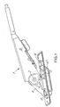
- the handbrake for motor vehicles shown in the drawing which is equipped with an automatic adjusting device and generally designated by 1, essentially consists of a handbrake lever 5 which is pivotable about a horizontal axis 2 and is mounted on a bridge support 4 which is provided with radially directed toothing 3 and which by means of a an actuating rod 6 can be locked out arbitrarily locking pawl 7 in any tightening position on the bridge girder 4.
- the bridge girder 4 is screwed to a trough 47 by means of screw bolts 8 and is connected to the trough with the vehicle body (not shown in the drawing).
- a one-armed lever 11 forming a driving device for at least one brake cable 10 is mounted on the axis 2 formed by a bearing part 9.
- the lever 11 forming the driving device is on the one hand freely rotatably supported via a bearing bore 12 on the one free end of the bearing part 9 and on the other hand is equipped with a connecting element 13 which is fixed in a bore recess of the lever 11 designed as a flat material by riveting and on the one hand a connecting pin 14 for the brake cable 10, on the other hand has a boom 15 for attacking the loading arm 16 of an adjusting spring 17.
- the adjusting spring 17 which acts continuously on the lever 11 forming the driving device is designed as a flat spiral spring and is fixed on the bearing part 9 forming the axis 2 by means of a clamping arm 18 and a sleeve (not shown in the drawing).
- the lever 11 forming the driving device With the hand brake lever 5, the lever 11 forming the driving device is in drive connection by means of a positive coupling 19 which engages automatically when the hand brake is applied.
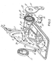
- the clutch 19 essentially consists of an axially adjustable clutch disc 20, a clutch release spring 21 and an axially directed toothing 22 on the lever 11 arranged concentrically with the bearing bore 12 thereof.
- the axially directed toothing 22 of the lever 11 forming the driving device is a complementary toothing 23 assigned to the clutch disc 20.
- the clutch disc 20 is arranged by means of a hexagon recess 24 in a non-rotatable but axially displaceable manner on a corresponding hexagon formation 24 of the bearing part 9, the hand brake lever 5 being arranged on the bearing part 9 in a rotationally secure manner by means of a connection recess likewise designed as a hexagon formation and not shown in detail in the drawing, such that each pivoting movement of the hand brake lever 5 inevitably results in a rotating movement of the clutch disc 20.
- the automatic and, depending on a tightening movement of the hand brake lever 5, the engagement of the positive clutch 22/23 disengaged when the hand brake lever 5 is in the release position under the action of the clutch release spring 21 designed as a plate spring is a segment-shaped arrangement arranged on the rear side 25 of the clutch disc 20 axially directed recesses 26 and on the bridge support 4 on an arranged on the bearing bore 27 for the bearing part 9 concentric circular engagement cam 28 existing engagement device.
- the clutch release spring 21 designed as a plate spring
- a total of three segment-shaped recesses 26 are provided on the rear side 25 of the clutch disc 20, which are evenly distributed over the edge zone and which are on the bridge support 4 on a circular path concentric with the bearing bore 27 in a gel-like mutual manner Distances arranged, the indentation cams 28 forming hump-shaped push-throughs are assigned.
- the segment-shaped recesses 26 on the rear of the clutch disc 20 on at least one of its radially directed edges with a bevel 29 forming a starting ramp for the hump-shaped push-throughs 28 on the bridge support 4 are provided.
- the hump-shaped push-throughs on the bridge carrier 4 forming the engagement cams 28 engage in the segment-shaped and axially directed recesses 26 on the rear side 25 of the clutch disc 20 when the handbrake lever 5 is in the release position, so that the clutch disc 20 can be held by the clutch release spring 21 in a displacement position in which its axially directed toothing 23 is out of engagement with the complementary axially directed toothing 22 of the lever 11 forming the driving device.
- the clutch disc 20 is also rotated by means of the hexagon formation 24, as a result of which the hump-shaped push-throughs on the bridge support 4 forming the engagement cams 28 with the starting ramps 29 on the segment-shaped recesses 26 on the rear side 25 of the clutch disc 20 overlap and, contrary to the action of the release spring 21, force an axial displacement of the clutch disc 20 in such a way that its axial toothing 23 engages in positive engagement with the axial toothing 22 on the lever 11 forming the driving device and thus a rigid coupling of the handbrake lever 5 the lever 11 is made.
Landscapes
- Engineering & Computer Science (AREA)
- Transportation (AREA)
- Mechanical Engineering (AREA)
- Braking Arrangements (AREA)
- Mechanical Operated Clutches (AREA)
- Regulating Braking Force (AREA)
Claims (10)
- Frein à main pour véhicules automobiles qui comporte un dispositif de réglage automatique et dans lequel un levier de frein à main (5) monté à pivotement sur un support en pont (4) doté d'un endentement (3) peut être immobilisé sur le support en pont dans une position de serrage quelconque au moyen d'un cliquet de blocage (7) pouvant être désengagé volontairement,
le levier de frein à main (5) pouvant être couplé au moyen d'un coupleur (19) contraint par ressort à un levier (11) monté de son côté également sur le support en pont (4) en vue de l'accouplement d'un câble de frein (10),
le coupleur (19) à verrouillage de forme, qui relie le levier (11) au levier de frein à main (5), se composant d'un disque d'accouplement (20) dentelé axialement et d'un endentement (22) axial complémentaire conformé sur le levier (11),
le levier de frein à main (5) réalisant grâce à un dispositif d'enclenchement une liaison d'entraínement par verrouillage de forme entre le coupleur (19) et le levier (11) lorsque l'on serre le frein à main, laquelle liaison est de nouveau supprimée lorsque le frein à main est desserré via un ressort d'accouplement et de désaccouplement (21),
caractérisé en ce qu'il est prévu un ressort de réglage (17) qui est fixé d'une part au support en pont (4) et qui contraint d'autre part le levier (11) et le câble de frein couplé au levier (11), le ressort de réglage (17) n'agissant que lorsque le ressort d'accouplement et de désaccouplement (21) a supprimé la liaison d'entraínement par verrouillage de forme. - Frein à main selon la revendication 1, caractérisé en ce que le levier de frein à main (5) et le disque d'accouplement (20) ainsi que le dispositif d'actionnement (11) sont supportés sur le support en pont (4) au moyen d'une pièce de palier commune (9) de façon à pouvoir pivoter autour d'un axe commun (2), le levier de frein à main (5) et le disque d'accouplement (20) étant couplés l'un à l'autre immobile en rotation.
- Frein à main selon la revendication 2, caractérisé en ce que le disque d'accouplement (20) est disposé de façon à pouvoir se déplacer axialement sur la pièce de palier (9) qui le supporte.
- Frein à main selon la revendication 2 ou 3, caractérisé en ce que le ressort de réglage (17) est conformé en ressort en spirale qui est d'une part supporté au niveau de la pièce de palier (9) et qui s'engage d'autre part avec le dispositif d'actionnement (11).
- Frein à main selon la revendication 4, caractérisé en ce que le dispositif d'actionnement est formé par un levier à bras unique (11) qui vient en engagement avec un bras de contrainte (16) dirigé radialement du ressort de réglage (17) via un élément de raccordement (13).
- Frein à main selon la revendication 4 ou 5, caractérisé en ce qu'un élément de raccordement (13), qui traverse le levier (11) conformé en pièce découpée de matériau plat, comporte d'une part un palier (15) approprié pour l'engagement du bras de contrainte (16) du ressort de réglage (17) et d'autre par un palier (14) destiné au câble de frein (10).
- Frein à main selon l'une des revendications 1 à 6, caractérisé en ce que le ressort d'accouplement et de désaccouplement est formé par un ressort à disques (21) inséré entre le disque d'accouplement (20) et le dispositif d'actionnement (11).
- Frein à main selon l'une des revendications 1 à 7, caractérisé en ce que le dispositif d'enclenchement se compose d'un certain nombre d'ergot d'enclenchement (28) disposés sur une surface de flanc du support en pont (4) et d'un nombre correspondant d'évidements (26) disposés au dos (25) du disque d'accouplement (20) et dotés de biseautages (29) formant des rampes d'avancement.
- Frein à main selon la revendication 8, caractérisé en ce que trois ergots d'enclenchement (28) sont conformés sur la surface de flanc du support en pont (4) avec une distribution uniforme autour de l'axe (2) supportant le levier de frein à main (5), lesquels trois ergots d'enclenchement (28) sont disposés également avec une distribution uniforme autour de l'axe (2) supportant le levier de frein à main (5) et sont associés à des évidements (26) en forme de segments en projection horizontale.
- Frein à main selon l'une des revendications 1 à 9, caractérisé en ce que le dispositif d'actionnement (11) et le ressort de réglage (17) sont disposés sur des côtés opposés l'un à l'autre du support en pont (4).
Applications Claiming Priority (2)
| Application Number | Priority Date | Filing Date | Title |
|---|---|---|---|
| DE19800603A DE19800603A1 (de) | 1998-01-11 | 1998-01-11 | Mit einer selbsttätigen Nachstelleinrichtung ausgestattete Handbremse für Kraftwagen |
| DE19800603 | 1998-01-11 |
Publications (3)
| Publication Number | Publication Date |
|---|---|
| EP0933271A2 EP0933271A2 (fr) | 1999-08-04 |
| EP0933271A3 EP0933271A3 (fr) | 2001-11-07 |
| EP0933271B1 true EP0933271B1 (fr) | 2004-01-02 |
Family
ID=7854249
Family Applications (1)
| Application Number | Title | Priority Date | Filing Date |
|---|---|---|---|
| EP98122531A Expired - Lifetime EP0933271B1 (fr) | 1998-01-11 | 1998-11-30 | Frein à main muni d'un dispositif de rattrapage automatique pour véhicules automobiles |
Country Status (5)
| Country | Link |
|---|---|
| US (1) | US6131483A (fr) |
| EP (1) | EP0933271B1 (fr) |
| CA (1) | CA2258385A1 (fr) |
| DE (2) | DE19800603A1 (fr) |
| SK (1) | SK1399A3 (fr) |
Families Citing this family (9)
| Publication number | Priority date | Publication date | Assignee | Title |
|---|---|---|---|---|
| DE19749551B4 (de) * | 1997-11-10 | 2005-05-19 | ED. SCHARWäCHTER GMBH | Mit einer selbsttätigen Nachstelleinrichtung ausgestattete Handbremse |
| US6286389B1 (en) * | 1999-01-21 | 2001-09-11 | Ventra Group Inc. | Parking brake actuating assembly with improved lockout structure |
| DE19936733C2 (de) * | 1999-08-06 | 2001-06-13 | Edscha Ag | Betätigungseinrichtung für eine Feststellbremse |
| KR100341294B1 (ko) | 2000-08-16 | 2002-06-22 | 이충곤 | 자동차 주차브레이크의 케이블 장력조절장치 |
| KR100461609B1 (ko) * | 2003-10-30 | 2004-12-13 | 경창산업주식회사 | 브레이크 케이블 장력 조절 기구를 포함하는 주차 브레이크 |
| WO2007026208A2 (fr) * | 2005-08-29 | 2007-03-08 | Ventra Group Inc. | Ensemble et procede de surveillance de la tension des freins |
| US8746109B2 (en) * | 2011-11-30 | 2014-06-10 | Magna Closures Inc. | Pop-up clutch parking brake actuator |
| US8925706B2 (en) | 2012-09-26 | 2015-01-06 | Dana Automotive Systems Group, Inc. | Vehicle parking brake control lever and pin with rollers |
| CN114893517B (zh) * | 2022-05-23 | 2023-08-15 | 伍仕明 | 一种简化制动间隙自动调整装置及鼓式制动器 |
Family Cites Families (10)
| Publication number | Priority date | Publication date | Assignee | Title |
|---|---|---|---|---|
| US4497399A (en) * | 1982-12-03 | 1985-02-05 | General Motors Corporation | Adjusting mechanism for a manually operated clutch |
| FR2563483B1 (fr) | 1984-04-26 | 1986-09-05 | Peugeot | Dispositif de commande d'un organe tel qu'un frein de stationnement d'un vehicule |
| US4819501A (en) * | 1988-04-12 | 1989-04-11 | Handy & Harman Automotive Group, Inc. | Self-adjusting brake mechanism |
| DE3900174C2 (de) * | 1989-01-05 | 1999-01-07 | Scharwaechter Gmbh Co Kg | Betätigungseinrichtung für eine Seilzug-Handbremse |
| WO1991019543A1 (fr) | 1990-06-15 | 1991-12-26 | 21St Century Anatomy, Inc. | Dispositif et procede d'exercice et de reeducation |
| US5448928A (en) * | 1993-11-19 | 1995-09-12 | Dura Automotive Systems, Inc. | Variable ratio parking brake lever with self-adjust cable tensioning means |
| US5467666A (en) * | 1994-07-07 | 1995-11-21 | Dura Automotive Systems, Inc. | Non-jamming self-adjust pawl and ratchet mechanism |
| AUPM784694A0 (en) * | 1994-09-02 | 1994-09-22 | Pbr Automotive Pty Ltd | Cable slack adjuster |
| US5718308A (en) * | 1996-02-02 | 1998-02-17 | Chung; Chiang-Hai | Automatic brake-adjusting device |
| US5875689A (en) * | 1997-02-25 | 1999-03-02 | Dura Automotive Systems, Inc. | Parking brake operating mechanism cable reel assembly having a bushing and support pin |
-
1998
- 1998-01-11 DE DE19800603A patent/DE19800603A1/de not_active Withdrawn
- 1998-11-30 EP EP98122531A patent/EP0933271B1/fr not_active Expired - Lifetime
- 1998-11-30 DE DE59810529T patent/DE59810529D1/de not_active Expired - Fee Related
-
1999
- 1999-01-05 CA CA002258385A patent/CA2258385A1/fr not_active Abandoned
- 1999-01-07 SK SK13-99A patent/SK1399A3/sk unknown
- 1999-01-07 US US09/227,046 patent/US6131483A/en not_active Expired - Fee Related
Also Published As
| Publication number | Publication date |
|---|---|
| EP0933271A2 (fr) | 1999-08-04 |
| DE19800603A1 (de) | 1999-07-15 |
| SK1399A3 (en) | 1999-07-12 |
| CA2258385A1 (fr) | 1999-07-11 |
| EP0933271A3 (fr) | 2001-11-07 |
| US6131483A (en) | 2000-10-17 |
| DE59810529D1 (de) | 2004-02-05 |
Similar Documents
| Publication | Publication Date | Title |
|---|---|---|
| DE69301652T2 (de) | Selbsttätige Nachstelleinrichtung für den Bremshebel einer S-Nocken-Fahrzeug-Trommelbremse | |
| DE3839117C2 (fr) | ||
| DE69921628T2 (de) | Steueranordnung für einen bremshebel | |
| DE60003262T2 (de) | Bremsvorrichtung mit Bremsnachstellungsvorrichtung | |
| DE4034165A1 (de) | Scheibenbremse fuer fahrzeuge | |
| DE202011106746U1 (de) | Bremshebel für eine Trommelbremse | |
| DE2507697C3 (de) | Abstützvorrichtung für die Bremsbacken einer Innenbackenbremse für auflaufgebremste Anhänger | |
| DE3502560A1 (de) | Bremsgestaenge fuer fahrzeugbremsen | |
| EP0933271B1 (fr) | Frein à main muni d'un dispositif de rattrapage automatique pour véhicules automobiles | |
| DE2443004A1 (de) | Nachstellvorrichtung fuer bremsen | |
| DE69713939T2 (de) | Trommelbremse mit nur einem Bremsschuh | |
| EP3165419B1 (fr) | Frein d`inertie pour remorque | |
| DE19527374C2 (de) | Taumelbeschlag für Fahrzeugsitze, insbesondere Kraftfahrzeugsitze | |
| EP0261660B1 (fr) | Frein de roue pour remorque | |
| DE4020485A1 (de) | Scheibenbremse fuer fahrzeuge | |
| DE3900174C2 (de) | Betätigungseinrichtung für eine Seilzug-Handbremse | |
| DE2741736A1 (de) | Innenbacken-trommelbremse | |
| DE1475516A1 (de) | Selbsttaetige Nachstellvorrichtung der Lose von Bremsen | |
| EP0388363B1 (fr) | Attelage pour véhicules | |
| DE2438755B2 (de) | Selbsttätige Nachstellvorrichtung für Fahrzeug-Außenbandbremsen | |
| DE2606925C3 (de) | Selbsttätige Nachstellvorrichtung für die Bremsbacken einer Innenbackenbremse | |
| DE2008139A1 (de) | Selbsttätige Nachstellvorrichtung fur den Bremshebel der Bremsnockenwelle einer Bremse | |
| DE3031891A1 (de) | Selbsttaetige nachstellvorrichtung fuer trommelbremsen | |
| DE2636047C2 (de) | Nachstellvorrichtung für die Anschläge einer Vollscheibenbremse | |
| DE3900661A1 (de) | Selbstnachstellende betaetigungseinrichtung fuer eine seilzug-handbremse |
Legal Events
| Date | Code | Title | Description |
|---|---|---|---|
| PUAI | Public reference made under article 153(3) epc to a published international application that has entered the european phase |
Free format text: ORIGINAL CODE: 0009012 |
|
| 17P | Request for examination filed |
Effective date: 19981130 |
|
| AK | Designated contracting states |
Kind code of ref document: A2 Designated state(s): AT BE CH CY DE DK ES FI FR GB GR IE IT LI LU MC NL PT SE Kind code of ref document: A2 Designated state(s): DE ES FR IT SE |
|
| AX | Request for extension of the european patent |
Free format text: AL;LT;LV;MK;RO;SI |
|
| PUAL | Search report despatched |
Free format text: ORIGINAL CODE: 0009013 |
|
| AK | Designated contracting states |
Kind code of ref document: A3 Designated state(s): AT BE CH CY DE DK ES FI FR GB GR IE IT LI LU MC NL PT SE |
|
| AX | Request for extension of the european patent |
Free format text: AL;LT;LV;MK;RO;SI |
|
| AKX | Designation fees paid |
Free format text: DE ES FR IT SE |
|
| 17Q | First examination report despatched |
Effective date: 20020813 |
|
| GRAH | Despatch of communication of intention to grant a patent |
Free format text: ORIGINAL CODE: EPIDOS IGRA |
|
| GRAS | Grant fee paid |
Free format text: ORIGINAL CODE: EPIDOSNIGR3 |
|
| GRAA | (expected) grant |
Free format text: ORIGINAL CODE: 0009210 |
|
| AK | Designated contracting states |
Kind code of ref document: B1 Designated state(s): DE ES FR IT SE |
|
| PG25 | Lapsed in a contracting state [announced via postgrant information from national office to epo] |
Ref country code: IT Free format text: LAPSE BECAUSE OF FAILURE TO SUBMIT A TRANSLATION OF THE DESCRIPTION OR TO PAY THE FEE WITHIN THE PRE;WARNING: LAPSES OF ITALIAN PATENTS WITH EFFECTIVE DATE BEFORE 2007 MAY HAVE OCCURRED AT ANY TIME BEFORE 2007. THE CORRECT EFFECTIVE DATE MAY BE DIFFERENT FROM THE ONE RECORDED.SCRIBED TIME-LIMIT Effective date: 20040102 Ref country code: FR Free format text: LAPSE BECAUSE OF FAILURE TO SUBMIT A TRANSLATION OF THE DESCRIPTION OR TO PAY THE FEE WITHIN THE PRESCRIBED TIME-LIMIT Effective date: 20040102 Ref country code: ES Free format text: LAPSE BECAUSE OF FAILURE TO SUBMIT A TRANSLATION OF THE DESCRIPTION OR TO PAY THE FEE WITHIN THE PRESCRIBED TIME-LIMIT Effective date: 20040102 |
|
| REF | Corresponds to: |
Ref document number: 59810529 Country of ref document: DE Date of ref document: 20040205 Kind code of ref document: P |
|
| PG25 | Lapsed in a contracting state [announced via postgrant information from national office to epo] |
Ref country code: SE Free format text: LAPSE BECAUSE OF FAILURE TO SUBMIT A TRANSLATION OF THE DESCRIPTION OR TO PAY THE FEE WITHIN THE PRESCRIBED TIME-LIMIT Effective date: 20040402 |
|
| PLBE | No opposition filed within time limit |
Free format text: ORIGINAL CODE: 0009261 |
|
| STAA | Information on the status of an ep patent application or granted ep patent |
Free format text: STATUS: NO OPPOSITION FILED WITHIN TIME LIMIT |
|
| 26N | No opposition filed |
Effective date: 20041005 |
|
| EN | Fr: translation not filed | ||
| PGFP | Annual fee paid to national office [announced via postgrant information from national office to epo] |
Ref country code: DE Payment date: 20050119 Year of fee payment: 7 |
|
| PG25 | Lapsed in a contracting state [announced via postgrant information from national office to epo] |
Ref country code: DE Free format text: LAPSE BECAUSE OF NON-PAYMENT OF DUE FEES Effective date: 20060601 |