EP0933458A2 - Reinigungsvorrichtung für das Nadelbett einer Flachstrickmaschine - Google Patents
Reinigungsvorrichtung für das Nadelbett einer Flachstrickmaschine Download PDFInfo
- Publication number
- EP0933458A2 EP0933458A2 EP99300814A EP99300814A EP0933458A2 EP 0933458 A2 EP0933458 A2 EP 0933458A2 EP 99300814 A EP99300814 A EP 99300814A EP 99300814 A EP99300814 A EP 99300814A EP 0933458 A2 EP0933458 A2 EP 0933458A2
- Authority
- EP
- European Patent Office
- Prior art keywords
- nozzle
- needle bed
- base
- knitting machine
- belt
- Prior art date
- Legal status (The legal status is an assumption and is not a legal conclusion. Google has not performed a legal analysis and makes no representation as to the accuracy of the status listed.)
- Granted
Links
Images




Classifications
-
- D—TEXTILES; PAPER
- D04—BRAIDING; LACE-MAKING; KNITTING; TRIMMINGS; NON-WOVEN FABRICS
- D04B—KNITTING
- D04B35/00—Details of, or auxiliary devices incorporated in, knitting machines, not otherwise provided for
- D04B35/32—Devices for removing lint or fluff
-
- B—PERFORMING OPERATIONS; TRANSPORTING
- B08—CLEANING
- B08B—CLEANING IN GENERAL; PREVENTION OF FOULING IN GENERAL
- B08B3/00—Cleaning by methods involving the use or presence of liquid or steam
- B08B3/02—Cleaning by the force of jets or sprays
-
- B—PERFORMING OPERATIONS; TRANSPORTING
- B08—CLEANING
- B08B—CLEANING IN GENERAL; PREVENTION OF FOULING IN GENERAL
- B08B5/00—Cleaning by methods involving the use of air flow or gas flow
- B08B5/04—Cleaning by suction, with or without auxiliary action
-
- D—TEXTILES; PAPER
- D04—BRAIDING; LACE-MAKING; KNITTING; TRIMMINGS; NON-WOVEN FABRICS
- D04B—KNITTING
- D04B15/00—Details of, or auxiliary devices incorporated in, weft knitting machines, restricted to machines of this kind
- D04B15/10—Needle beds
-
- D—TEXTILES; PAPER
- D04—BRAIDING; LACE-MAKING; KNITTING; TRIMMINGS; NON-WOVEN FABRICS
- D04B—KNITTING
- D04B37/00—Auxiliary apparatus or devices for use with knitting machines
- D04B37/02—Auxiliary apparatus or devices for use with knitting machines with weft knitting machines
Definitions
- the present invention relates to a needle bed cleaner for a flat knitting machine having at least a front needle bed and a back needle bed.
- Nozzles of these needle bed cleaners reciprocate in the longitudinal direction of needle beds of a flat knitting machine. They clean and remove fiber waste of yarn, dust, etc. sticking around the trick gap between the front needle bed and the back needle bed. Cleaning and removal of dust, etc. is effected by suction of air, and this system does not scatter dust.
- a nozzle of a cleaner travelling over the needle beds and blower fixed on the base of a flat knitting machine is connected with a flexible tube of plastics. So, irrespective of the position of the nozzle over the needle beds, the plastic tube is deformed according to the position of the nozzle, and suction is effected at a suction port in the top end of the nozzle.
- the plastic tube however, lacks positional stability as it is deformed momentarily with travelling of the nozzle. So the pipe work needs a guiding mechanism for the tube and poses a problem of piping space.
- said joint further has two base rollers on both sides of the first roller for making the belt contact the opening at both side ends of the base.
- the needle bed cleaner is provided with connecting means for connecting and releasing the nozzle to and from the carriage at a side end of the flat knitting machine.
- said nozzle has a suction port
- the needle bed cleaner is provided with a nozzle shifter for shifting the suction port between a cleaning position where the suction port is extending close to a trick gap between the needle beds and a retreated position where the suction port is moved away from the trick gap.
- a negative pressure generated by the blower reaches the base duct.
- the base duct is arranged in parallel with, for example, a back needle bed of the flat knitting machine.
- On one face of the base duct there is at least an opening such as a slit extending on the base duct in its longitudinal direction.
- the belt extends over the opening in this face. It is sucked onto the base duct by the negative pressure in the base duct, covers the opening, and makes the base duct air tight.
- a joint that connects the base duct and the nozzle travels in relation to the base duct and the belt, and a top roller provided near the top of the base of the joint partially peels the belt from the base duct. Thus, the location of peeling shifts successively.
- said joint is also provided with a pair of base rollers on both sides of said roller, and the base rollers make the belt closely contact the opening in the base duct.
- a driving motor for reciprocating the carriage may also serve as nozzle travelling means, and the nozzle can be connected with and disconnected from the carriage.
- the connection with the carriage is undone at one side end of the knitting machine, and when the needle beds are cleaned, the nozzle is connected with the carriage. Therefore, when the cleaner is not used, connection between the carriage and the nozzle is undone by the connecting means. When the cleaner is used, the connection is established and the nozzle is trained to desired positions by the moving carriage.
- the needle bed cleaner may be provided with a nozzle shifter that shifts the suction port of the nozzle between the cleaning position at which said suction port is extending close to the trick gap and the retreated position at which said suction port is moved away from the trick gap.
- a nozzle shifter that shifts the suction port of the nozzle between the cleaning position at which said suction port is extending close to the trick gap and the retreated position at which said suction port is moved away from the trick gap.
- the needle bed cleaner of the present invention is installed compactly in a flat knitting machine, posing no problems of pipe work that have been common to conventional flexible pipe works and enhancing space-saving.
- the invention provides a knitting machine in a space saving and compact way, a pipe work of a needle bed cleaner that forms a vent channel connecting a blower and a nozzle travelling over needle beds; a means of halting the nozzle at a side end of the knitting machine while knitting is effected by a carriage, making the nozzle travel over the needle beds only when cleaning is required and using an existing driving power for the carriage for the shift of this nozzle; and a needle bed cleaner having a shifter that makes the nozzle stand by in a retracted position where the nozzle does not interfere with any yarn feeder.
- Fig. 1 is a plan view of a flat knitting machine having a needle bed cleaner of an embodiment of the present invention with parts broken away for clarity.
- Fig. 2 is a fragmentary side view of the flat knitting machine having the needle bed cleaner of the embodiment.
- Fig. 3 is a fragmentary rear view showing the needle bed cleaner of the embodiment and the carriage of the flat knitting machine.
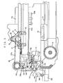
- Fig. 4 is an enlarged view of a part of Fig. 2, showing the nozzle of the needle bed cleaner standing by at one side end of the flat knitting machine.
- Fig. 5 is an enlarged view of a part of Fig. 3, showing the nozzle that is connected with the carriage at a side end of the flat knitting machine by connecting means.
- Fig. 6 is a sectional view of a joint of the needle bed cleaner. The section is parallel to the longitudinal direction of the needle beds.
- Fig. 7 is a sectional view of the joint of the needle bed cleaner along the line VII-VII of Fig. 6.
- Fig. 8 is a fragmentary enlarged side view showing the needle bed cleaner that is cleaning.
- Fig. 9 shows the nozzle and the nozzle shifter provided in the needle bed cleaner.
- the suction port of the nozzle is extended to the cleaning position.
- Fig. 10 shows the nozzle and the nozzle shifter provided in the needle bed cleaner.
- the suction port of the nozzle is retracted to the retreated position.
- Fig. 1 is a plan view showing the flat knitting machine.
- Fig. 2 is a side view of the flat knitting machine.
- Fig. 3 is a rear view. It should be noted that to clearly show the arrangement of the needle bed cleaner, tension equipment, cone stands, carrier rails, carrier rail brackets, etc. are omitted in Fig. 1. Similarly, needle beds, frames and yarn feeders are omitted in Fig. 3.
- Fig. 4 is an enlarged view of a part of Fig. 2.
- Fig. 5 is an enlarged view of a part of Fig. 3.
- a bed 5 is supported on a right frame 3 and a left frame 3 of a flat knitting machine 1. Needle beds 9b, 9f on which a large number of knitting needles 7 are aligned are arranged on the bed 5, the former in the back and the latter in the front, with a trick gap in between them.
- a carriage 11 comprises back and front carriages 11b, 11f. The carriage 11 is connected and fixed onto a driving belt 15 by a connecting part 16. The driving belt 15 is stretched between pulleys 13, 14 that are provided on the left and on the right, respectively.
- the pulley 13 is a reducing pulley and, as shown in Fig. 2, it is connected, by a driving belt 21, to a driving pulley 19 of a driving motor 17 that is fixed on the frame 3.
- the pulley 13 converts rotation of the driving motor 17 into reciprocative motion of the driving belt 15 to make the carriage 11 reciprocate along the needle beds 9.
- the yarn feeders 9 feed yarn to knitting needles 7 on the needle beds 9, and the carriage 11 moves knitting needles 7 forward and backward to knit a knitted fabric.
- 23f and 23b denote guide rails for carriage that guide the carriage 11 above the needle beds.
- 25 denotes yarn feeders held on yarn rails. Initially, the yarn feeders 25 stand still on both the outer sides of the needle beds 9. Normally two to four yarn rails are provided in a flat knitting machine. These yarn rails are suspended by yarn rail supporting brackets (not illustrated) at both ends thereof. A mounting position 27 of a yarn rail supporting bracket onto the bed 5 is indicated by a dashed line.
- 30 denotes a needle bed cleaner. In Fig. 1, the needle bed cleaner 30 is on standby at one side end of the knitting machine.
- 33f denotes a front cover of the flat knitting machine and 33b denotes
- the needle bed cleaner 30 includes a nozzle 37 that travels along the needle beds 9 and has a suction port, a nozzle support 39 for supporting the nozzle 37, a base duct 43 that connects the nozzle 37 and a blower 41 having a blower motor, and a joint 45 for connecting the nozzle 37 and the base duct 43.
- the cleaner also includes nozzle travelling means for travelling the nozzle 37 along the needle beds 9.
- the nozzle support 39 shown in Fig. 2 is approximately T-shaped when seen from the side, and its lower end 39a is slidably supported via rollers on the rear guide rail for carriage 23b. A top end part 39b of the T supports the nozzle 37.
- the base duct 43 is longer than the needle beds 9 and is a metal rectangular tube with a rectangular section.
- the base duct 43 is fixed to a rear cover 33b by support brackets 49.
- the rear cover 33b covers the rear of the flat knitting machine.
- a slit 51 shown in Fig. 1 is formed in the base duct 43 along one face thereof, for example on the top face. In place of the slit, a large number of through holes may be formed.
- the slit 51 is formed over the full length of the base duct in the center of the top face of the base duct 43.
- a belt 53 of, for example, nylon that is wider than the width of the slit, non air-permeable and flexible is stretched to cover the slit. Both ends of the belt 53 are fixed onto the base duct.
- the belt 53 is suctioned to a supporting face 43a, in which the slit 51 is formed, of the base duct 43.
- the belt 53 prevents the loss of the negative pressure through the slit 51 and in turn a rise in air pressure in the base duct 43.
- an opening 55 shown in Fig. 3, etc. is formed, and the blower 41 fixed on the frame 3 and the opening 55 are connected with a flexible plastic tube 57.
- a part of the base duct 43 for example a central part thereof may be extended downward and directly connected with the blower 41. Then, the plastic tube 57 is not needed.
- Fig. 6 shows a transverse section of the joint 45 or the section that is parallel to the longitudinal direction of the needle beds.
- Fig. 7 shows a longitudinal section thereof or the section that is perpendicular to the needle beds.
- a joint base 70 of the joint 45 is supported on the base duct 43 in such a way that it can travel freely in the longitudinal direction of the duct.
- Rollers 63, 64, 65 that are installed on the joint base 70 are rotatably inserted into guiding grooves of guide rails 61, 62 that are mounted on the base duct 43.
- the joint 45 is provided with a belt support means 67.
- the joint base 70 When seen from the front, the joint base 70 is triangular. Between a base front 71 and a base rear 72, three rollers 73, 75, 77 of which rotating axes are in the same direction as those of the pulleys 13, 14 are rotatably supported by bearings that are provided near the respective corners of the triangle. As shown in Fig. 6, the belt 53 is threaded through the rollers 73, 75, 77. The base rollers 73, 77 that are located in lower positions prevents the belt that covers the slit 51 from lifting from the supporting face 43a. The top roller 75 that is located at the vertex of the triangle peels the belt 53 between the base rollers 73, 75 from the slit 51.
- the joint base 70 and rollers 73, 75, 77 constitute the belt support means 67.
- an L-shaped vent channel 81 is integrally formed inside the joint base 70.
- One opening 81a of the vent channel 81 is connected to the slit 51 of the base duct 43.
- the other opening 81b thereof is formed in a front protruding portion of the base front 71 and this opening 81b is connected to the back end 37b of the nozzle 37.
- 83 denotes a packing that is rectangular and has an insertion hole 83a at the center thereof.
- the opening 81a of the vent channel is connected to the insertion hole 83a, and the packing 83 prevents loss of the negative pressure.
- a suction channel is formed between the blower 41 and the nozzle 37.
- the motor 17 for reciprocating the carriage is also used as the nozzle travelling means to reciprocate the nozzle 37 along the needle beds 9.
- connecting means 110 for the nozzle 38 and the carriage 11 will be described.
- the rear carriage 11b is provided with a connecting part that engages with a claw 115b of a rocking lever that is provided on the nozzle support 39.
- This connecting part is composed of a connecting pin 111 and a pin mount 113.
- the rocking lever 115 is supported on the nozzle support 39 by a shaft at the central part 115a thereof.
- the claw 115b for engaging with the connecting pin 111 is formed at one end of the rocking lever 115, and the other end thereof is connected with a link 117 that is provided on the nozzle support 39.
- the rocking lever 115 is supported at a central part 115a thereof, and the top end of the rocking lever 115 is constantly energized upward by a helix coil that is fixed to the central part 115a, and the claw 115b engages with the connecting pin 111.
- a roller 121 is supported on a shaft at the lower end of the link 117, and this roller engages with a cam surface 125a of a control lever 125.
- This control lever 125 is a part of a control 123 that is provided at the nozzle standby position at one side end of the flat knitting machine proper.
- the control lever 125 is L-shaped when seen from its side.
- the control lever 125 is supported on a shaft at a bending part 125b of the L-shaped body in such a way that the cam face 125a formed on the upper edge of the lever swings to and fro.
- control lever 125 is energized by a spring 127 that is provided beneath the lower end of the L-shaped body in such a way that the cam face 125a engages with the roller 121.
- a solenoid 129 is provided above the lower end of the control lever 125 to swing the control lever 125.
- Fig. 5 and Fig. 8 show a state that the nozzle 37 is connected with the carriage 11.
- the solenoid 129 When the solenoid 129 is actuated, the cam face 125a of the control lever swings backward.
- the engagement between the roller 121 and the control lever 125 is removed, and because of the energizing force of the helix coil 119, the link 117 slides downward.
- the claw 115a of the rocking lever will swing upward to catch the connecting pin 111 provided on the carriage 11 and connect the nozzle 37 and the carriage 11.
- the nozzle 37 When the carriage 11 travels under this condition, the nozzle 37 will travel as well.
- the blower is operated to clean the needle beds by the cleaner.
- the carriage travels back to the one side of the knitting machine.
- the solenoid 129 is not in operation, and the control lever 125 has been swung by the spring 127 and the cam face 125a is in a position where it engages with the roller 121.
- the roller 121 will come to contact with the cam face 125a of the control lever.
- the roller 121 is pushed upward gradually by the slope of the cam face 125a.
- the link 117 slides upward and the top end of the rocking lever 115 swings downward, and the claw 115a is disconnected from the connecting pin 111.
- a nozzle shifter 140 that is provided in the needle bed cleaner 30 will be described.
- Fig. 9 shows the nozzle that is advanced to a cleaning position.
- Fig. 10 shows the nozzle that is retracted into a retreated position.
- the nozzle 37 in the embodiment is composed of a joint 141, a fixed nozzle 137a and a movable nozzle 137b.
- the top end of the fixed nozzle 137a is connected to the joint 141 that is mounted on the nozzle support 39, and the back end thereof extends to the joint 45.
- the movable nozzle 137b has the suction port 37a and is mounted on the joint 141 in such a way that the movable nozzle 137b comes close to or moves away from the trick gap.
- a link 143 extending in the front-rear direction is connected to the movable nozzle 137b, and the back end of the link 143 is connected to a lever 145 that is supported on a shaft on the nozzle support 39.
- rollers 150, 151 are supported on shafts at the front side of the top end of one of two-pronged portions thereof and at the back side of the top end of the other prong, respectively. They engage with cams 147a, 147b that are mounted in two rows, upper one and lower one, on the base duct 43.
- 153 in Fig. 9 denotes a spring that is arranged between the nozzle support 39 and the lever 145. The spring 153 holds the lever position when the lever is turned, thus preventing inadvertent motion of the lever 145.
- 133 denotes a connecting piece that fixes the nozzle 37 and the joint base 70 of the joint 45 to each other.
- the carriage 11 is made to travel up to a position adjacent to an area S between the yarn feeders standing in the initial position and one side end of the needle beds 9 (see Fig. 1).
- the roller 151 of the lever 145 rolls over the cam face of the upper cam 147a and the link 143 moves backward; thus the nozzle suction port 37a assumes its retreated position.
- the roller 150 that is mounted on the bottom of the lever 145 will engage with the cam face of the lower cam 147b and the roller 150 will be pushed forward.
- the nozzle shifter 140 prevents interference between the top end of the nozzle and the yarn feeders. Moreover, at the side end of the knitting machine, interference with the bracket for supporting yarn rails is prevented, and increase in the width of the knitting machine is prevented.
- the nozzle suction port is shifted forward and backward by the linkage between the cleaning position and the retreated position. However, if a linkage that shifts the nozzle upward and downward concurrently with its forward and backward shift is used, the nozzle suction port can go over the top ends of the inverted-V-shaped front and back needle beds when seen from the side. Thus the nozzle can be advanced or retreated not only in the area S but also at any position over the needle beds.
- the nozzle of the needle bed cleaner is supported by a nozzle support that is slidable on the carriage rails, and the nozzle is connected with or disconnected from the carriage by the connecting means that is provided on the nozzle support.
- the nozzle support can be omitted.
- a separate driving motor may be provided as nozzle travelling means, and in this case, no means for connecting with the carriage is required.
Landscapes
- Engineering & Computer Science (AREA)
- Textile Engineering (AREA)
- Knitting Machines (AREA)
Applications Claiming Priority (2)
| Application Number | Priority Date | Filing Date | Title |
|---|---|---|---|
| JP02193498A JP3757048B2 (ja) | 1998-02-03 | 1998-02-03 | 横編機のニードルベッドクリーナ |
| JP2193498 | 1998-02-03 |
Publications (3)
| Publication Number | Publication Date |
|---|---|
| EP0933458A2 true EP0933458A2 (de) | 1999-08-04 |
| EP0933458A3 EP0933458A3 (de) | 2000-07-05 |
| EP0933458B1 EP0933458B1 (de) | 2003-11-26 |
Family
ID=12068888
Family Applications (1)
| Application Number | Title | Priority Date | Filing Date |
|---|---|---|---|
| EP99300814A Expired - Lifetime EP0933458B1 (de) | 1998-02-03 | 1999-02-03 | Reinigungsvorrichtung für das Nadelbett einer Flachstrickmaschine |
Country Status (6)
| Country | Link |
|---|---|
| US (1) | US6094946A (de) |
| EP (1) | EP0933458B1 (de) |
| JP (1) | JP3757048B2 (de) |
| KR (1) | KR100514779B1 (de) |
| DE (1) | DE69913008T2 (de) |
| TW (1) | TW558574B (de) |
Cited By (2)
| Publication number | Priority date | Publication date | Assignee | Title |
|---|---|---|---|---|
| CN104246041A (zh) * | 2012-04-26 | 2014-12-24 | 马尔切洛·加廖托 | 用于清洁用于针织机的针盒板的机器 |
| CN107489657A (zh) * | 2017-08-29 | 2017-12-19 | 海宁市成达经编有限公司 | 经编机导经装置中的风机安装结构 |
Families Citing this family (5)
| Publication number | Priority date | Publication date | Assignee | Title |
|---|---|---|---|---|
| AU2002246853A1 (en) * | 2000-10-19 | 2002-07-30 | Teradyne, Inc. | Method and apparatus for bridged tap impact analysis |
| CN107099930B (zh) * | 2017-07-03 | 2018-12-07 | 浙江宏锋经纬编有限公司 | 一种经编丝往复除尘机构 |
| KR20190008662A (ko) | 2017-07-17 | 2019-01-25 | 한국항공우주산업 주식회사 | 클리닝 장치 |
| CN110125066A (zh) * | 2019-03-21 | 2019-08-16 | 力颖自动化设备(昆山)有限公司 | 全自动电脑横机针板清洗机及其控制方法 |
| CN112481796B (zh) * | 2020-12-25 | 2022-07-19 | 上海华翔羊毛衫有限公司 | 一种数控针织设备 |
Family Cites Families (8)
| Publication number | Priority date | Publication date | Assignee | Title |
|---|---|---|---|---|
| GB1110607A (en) * | 1964-06-19 | 1968-04-24 | Carrier Engineering Co Ltd | Improvements in or relating to suction apparatus for textile machines |
| JPS5520169B2 (de) * | 1974-04-10 | 1980-05-31 | ||
| DE3130584A1 (de) * | 1981-08-01 | 1983-02-17 | Seitz, Herbert, 8500 Nürnberg | Vorrichtung zum reinigen und entstauben von flachstrickmaschinen im bereich des strickvorganges |
| DE3506142A1 (de) * | 1985-02-22 | 1986-10-30 | Seitz, Herbert, 8500 Nürnberg | Entstaubungsvorrichtung fuer flachstrickmaschinen |
| DE3626759C2 (de) * | 1986-08-07 | 1994-09-15 | Stoll & Co H | Entstaubungsvorrichtung für Flachstrickmaschinen |
| DE3635096A1 (de) * | 1986-10-15 | 1988-04-21 | Stoll & Co H | Entstaubungsvorrichtung fuer flachstrickmaschinen |
| JP3283308B2 (ja) * | 1992-10-20 | 2002-05-20 | 株式会社福原精機製作所 | 編機の編成部における除塵・給油用噴出ノズル装置 |
| JPH07229040A (ja) * | 1994-02-15 | 1995-08-29 | Japan Le-Wa Kk | 横編機における塵埃除去装置 |
-
1998
- 1998-02-03 JP JP02193498A patent/JP3757048B2/ja not_active Expired - Fee Related
-
1999
- 1999-01-28 TW TW088101261A patent/TW558574B/zh not_active IP Right Cessation
- 1999-02-02 US US09/241,734 patent/US6094946A/en not_active Expired - Fee Related
- 1999-02-03 KR KR10-1999-0003632A patent/KR100514779B1/ko not_active Expired - Fee Related
- 1999-02-03 EP EP99300814A patent/EP0933458B1/de not_active Expired - Lifetime
- 1999-02-03 DE DE69913008T patent/DE69913008T2/de not_active Expired - Lifetime
Cited By (3)
| Publication number | Priority date | Publication date | Assignee | Title |
|---|---|---|---|---|
| CN104246041A (zh) * | 2012-04-26 | 2014-12-24 | 马尔切洛·加廖托 | 用于清洁用于针织机的针盒板的机器 |
| CN107489657A (zh) * | 2017-08-29 | 2017-12-19 | 海宁市成达经编有限公司 | 经编机导经装置中的风机安装结构 |
| CN107489657B (zh) * | 2017-08-29 | 2019-05-28 | 海宁市成达经编有限公司 | 经编机导经装置中的风机安装结构 |
Also Published As
| Publication number | Publication date |
|---|---|
| DE69913008T2 (de) | 2004-04-15 |
| DE69913008D1 (de) | 2004-01-08 |
| US6094946A (en) | 2000-08-01 |
| EP0933458A3 (de) | 2000-07-05 |
| JPH11222753A (ja) | 1999-08-17 |
| TW558574B (en) | 2003-10-21 |
| EP0933458B1 (de) | 2003-11-26 |
| JP3757048B2 (ja) | 2006-03-22 |
| KR19990072398A (ko) | 1999-09-27 |
| KR100514779B1 (ko) | 2005-09-13 |
Similar Documents
| Publication | Publication Date | Title |
|---|---|---|
| EP0933458B1 (de) | Reinigungsvorrichtung für das Nadelbett einer Flachstrickmaschine | |
| US4957051A (en) | Automatic fitting apparatus for hose part of half made pantyhose | |
| US4120251A (en) | Automatic method and apparatus for closing a toe end of a seamless hose material utilizing a straight line stitching by means of a stationarily disposed sewing machine | |
| CN114717696B (zh) | 一种洁净型纺纱装置 | |
| CN213328278U (zh) | 一种定型机及其脱袜机构 | |
| KR20040088784A (ko) | 양말 봉조장치 | |
| CN112571933A (zh) | 一种纺织面料印染装置 | |
| US5159805A (en) | Guide arrangement for peg trays on a ring spinning machine | |
| JPS6333871Y2 (de) | ||
| CN121609165B (zh) | 一种自动打纱机 | |
| JP3587063B2 (ja) | 洗車機 | |
| CN218875005U (zh) | 一种缝纫机配件拉光装置 | |
| EP0149295B1 (de) | Vorrichtung zum Verarbeiten von rundgestrickten Maschenwaren | |
| KR950007655Y1 (ko) | 자수용 양말의 장착틀 분리장치 | |
| KR20020063406A (ko) | 자수기의 집진 장치 | |
| JP3074467U (ja) | シート素材の縁飾り装置 | |
| CN119507112A (zh) | 一种除尘式大提花一体成型针织机 | |
| KR200276744Y1 (ko) | 섬유기계용 보빈의 잔사제거장치 | |
| KR950002041Y1 (ko) | 카세트의 테이프가이드 공급장치 | |
| US5596942A (en) | Feeding support for a sewn product | |
| JPH07166452A (ja) | クリーニング装置 | |
| CN120246382A (zh) | 一种家用纺织品便于清洁的输送装置 | |
| JPH03279425A (ja) | 粗糸ボビン搬送システム | |
| JPH073574A (ja) | 浮き緯糸の抜き上げ装置 | |
| CN112481840A (zh) | 一种毛毯布的自动包边装置 |
Legal Events
| Date | Code | Title | Description |
|---|---|---|---|
| PUAI | Public reference made under article 153(3) epc to a published international application that has entered the european phase |
Free format text: ORIGINAL CODE: 0009012 |
|
| AK | Designated contracting states |
Kind code of ref document: A2 Designated state(s): DE FR GB IT |
|
| AX | Request for extension of the european patent |
Free format text: AL;LT;LV;MK;RO;SI |
|
| PUAL | Search report despatched |
Free format text: ORIGINAL CODE: 0009013 |
|
| AK | Designated contracting states |
Kind code of ref document: A3 Designated state(s): AT BE CH CY DE DK ES FI FR GB GR IE IT LI LU MC NL PT SE |
|
| AX | Request for extension of the european patent |
Free format text: AL;LT;LV;MK;RO;SI |
|
| 17P | Request for examination filed |
Effective date: 20000807 |
|
| AKX | Designation fees paid |
Free format text: DE FR GB IT |
|
| 17Q | First examination report despatched |
Effective date: 20020809 |
|
| GRAH | Despatch of communication of intention to grant a patent |
Free format text: ORIGINAL CODE: EPIDOS IGRA |
|
| GRAS | Grant fee paid |
Free format text: ORIGINAL CODE: EPIDOSNIGR3 |
|
| GRAA | (expected) grant |
Free format text: ORIGINAL CODE: 0009210 |
|
| AK | Designated contracting states |
Kind code of ref document: B1 Designated state(s): DE FR GB IT |
|
| REG | Reference to a national code |
Ref country code: GB Ref legal event code: FG4D |
|
| REF | Corresponds to: |
Ref document number: 69913008 Country of ref document: DE Date of ref document: 20040108 Kind code of ref document: P |
|
| ET | Fr: translation filed | ||
| PLBE | No opposition filed within time limit |
Free format text: ORIGINAL CODE: 0009261 |
|
| STAA | Information on the status of an ep patent application or granted ep patent |
Free format text: STATUS: NO OPPOSITION FILED WITHIN TIME LIMIT |
|
| 26N | No opposition filed |
Effective date: 20040827 |
|
| PGFP | Annual fee paid to national office [announced via postgrant information from national office to epo] |
Ref country code: FR Payment date: 20100223 Year of fee payment: 12 |
|
| PGFP | Annual fee paid to national office [announced via postgrant information from national office to epo] |
Ref country code: GB Payment date: 20100202 Year of fee payment: 12 |
|
| PGFP | Annual fee paid to national office [announced via postgrant information from national office to epo] |
Ref country code: IT Payment date: 20110212 Year of fee payment: 13 Ref country code: DE Payment date: 20110126 Year of fee payment: 13 |
|
| GBPC | Gb: european patent ceased through non-payment of renewal fee |
Effective date: 20110203 |
|
| REG | Reference to a national code |
Ref country code: FR Ref legal event code: ST Effective date: 20111102 |
|
| PG25 | Lapsed in a contracting state [announced via postgrant information from national office to epo] |
Ref country code: FR Free format text: LAPSE BECAUSE OF NON-PAYMENT OF DUE FEES Effective date: 20110228 |
|
| PG25 | Lapsed in a contracting state [announced via postgrant information from national office to epo] |
Ref country code: GB Free format text: LAPSE BECAUSE OF NON-PAYMENT OF DUE FEES Effective date: 20110203 |
|
| PG25 | Lapsed in a contracting state [announced via postgrant information from national office to epo] |
Ref country code: IT Free format text: LAPSE BECAUSE OF NON-PAYMENT OF DUE FEES Effective date: 20120203 |
|
| REG | Reference to a national code |
Ref country code: DE Ref legal event code: R119 Ref document number: 69913008 Country of ref document: DE Effective date: 20120901 |
|
| PG25 | Lapsed in a contracting state [announced via postgrant information from national office to epo] |
Ref country code: DE Free format text: LAPSE BECAUSE OF NON-PAYMENT OF DUE FEES Effective date: 20120901 |