EP0933471A2 - Presse du chaussure - Google Patents
Presse du chaussure Download PDFInfo
- Publication number
- EP0933471A2 EP0933471A2 EP99850014A EP99850014A EP0933471A2 EP 0933471 A2 EP0933471 A2 EP 0933471A2 EP 99850014 A EP99850014 A EP 99850014A EP 99850014 A EP99850014 A EP 99850014A EP 0933471 A2 EP0933471 A2 EP 0933471A2
- Authority
- EP
- European Patent Office
- Prior art keywords
- shoe
- press
- piston
- cylinder
- support
- Prior art date
- Legal status (The legal status is an assumption and is not a legal conclusion. Google has not performed a legal analysis and makes no representation as to the accuracy of the status listed.)
- Granted
Links
- 239000012530 fluid Substances 0.000 claims abstract description 31
- 238000003825 pressing Methods 0.000 claims abstract description 7
- 238000007789 sealing Methods 0.000 claims description 6
- 238000004891 communication Methods 0.000 claims description 3
- 238000005452 bending Methods 0.000 description 8
- 238000011144 upstream manufacturing Methods 0.000 description 8
- 239000000463 material Substances 0.000 description 6
- 230000004323 axial length Effects 0.000 description 5
- 239000000123 paper Substances 0.000 description 4
- 230000002745 absorbent Effects 0.000 description 3
- 239000002250 absorbent Substances 0.000 description 3
- 238000012986 modification Methods 0.000 description 2
- 230000004048 modification Effects 0.000 description 2
- 239000011087 paperboard Substances 0.000 description 2
- 238000006467 substitution reaction Methods 0.000 description 2
- 238000013519 translation Methods 0.000 description 2
- 230000014616 translation Effects 0.000 description 2
- 229910000906 Bronze Inorganic materials 0.000 description 1
- 239000000654 additive Substances 0.000 description 1
- 239000010974 bronze Substances 0.000 description 1
- 238000003490 calendering Methods 0.000 description 1
- 230000000295 complement effect Effects 0.000 description 1
- 238000010276 construction Methods 0.000 description 1
- KUNSUQLRTQLHQQ-UHFFFAOYSA-N copper tin Chemical compound [Cu].[Sn] KUNSUQLRTQLHQQ-UHFFFAOYSA-N 0.000 description 1
- 230000003247 decreasing effect Effects 0.000 description 1
- 238000010438 heat treatment Methods 0.000 description 1
- 230000002706 hydrostatic effect Effects 0.000 description 1
- 238000005461 lubrication Methods 0.000 description 1
- 230000007257 malfunction Effects 0.000 description 1
- 229920000642 polymer Polymers 0.000 description 1
- 230000000452 restraining effect Effects 0.000 description 1
- 239000007787 solid Substances 0.000 description 1
Images


Classifications
-
- D—TEXTILES; PAPER
- D21—PAPER-MAKING; PRODUCTION OF CELLULOSE
- D21F—PAPER-MAKING MACHINES; METHODS OF PRODUCING PAPER THEREON
- D21F3/00—Press section of machines for making continuous webs of paper
- D21F3/02—Wet presses
- D21F3/0209—Wet presses with extended press nip
- D21F3/0218—Shoe presses
Definitions
- the present invention relates to shoe presses for applying pressure to a running web of paper, paperboard, or the like. More particularly, the present invention relates to a shoe press of the type having a support which supports a press shoe adjacent to a counter roll or other backing member such that the press shoe and backing member form an extended nip therebetween, and having a hydraulic device for urging the press shoe toward the backing member to apply pressure to the web running through the nip.
- a wet web of paper or the like from the forming section of the machine is typically carried through the nip of a shoe press of the above-described type, where the web is pressed between two layers of absorbent felt or the like for wicking moisture from the web.
- shoe presses can also be used for calendering the web downstream of the forming section.
- U.S. Patent No. 4,917,768 which is commonly owned with the present application, discloses a shoe press in which the press shoe is carried on the support by tubular sleeves rigidly affixed to and spaced apart on the support along the cross-machine direction, the sleeves being slidably received within cylindrical recesses in the press shoe to permit the press shoe to be moved toward and away from a counter roll for varying the nip pressure.
- the shoe press includes hydraulic jacks upstream and downstream of the sleeves for urging the press shoe toward the counter roll and for pivoting the shoe about a cross-machine axis so as to vary the nip pressure in the machine direction.
- the press shoe is capable of pivoting relative to the support for varying the nip pressure in the machine direction.
- the pistons are placed in bending within the cylinders of the hydraulic jacks, and such bending can lead to malfunction of the jacks, particularly for the cylinders toward the outer ends of the shoe farthest from the centerline where thermal expansion results in relatively greater translation of the shoe relative to the support and pistons. Bending of the pistons is undesirable from the standpoint of wear on the pistons, cylinders, and seals, and can also interfere with proper functioning of the press. Additionally, thermal expansion of the shoe can cause leakage of hydraulic fluid when the seals are excessively deformed.
- the shoe press includes a press shoe that extends in a cross-machine direction along the full width of a web being carried through the press, and a plurality of articulated hydraulic loading cylinders spaced apart along the shoe in the cross-machine direction and supported by a support.
- the loading cylinders define working chambers that are pressurizable by hydraulic fluid so as to cause the loading cylinders to urge the press shoe away from the support and toward a counter roll or other backing member for applying pressure to the web being carried through the nip defined between the shoe and the backing member.
- Each loading cylinder comprises a piston member disposed within a cylinder member.
- One of the piston and cylinder members comprises a two-piece member having a first member fixed relative to the press shoe and a second member fixed relative to the support, while the other of the piston and cylinder members comprises a coupler.
- the two-piece member comprises first and second cylinders and the coupler comprises a piston which is slidably received within both of the cylinders.
- the two-piece member comprises first and second pistons and the coupler comprises a cylinder which surrounds both of the pistons.
- each coupler sealingly engages both the first and second members such that the first member is urged away from the second member in a loading direction by pressurization of the working chamber to cause the press shoe to be urged toward the backing member.
- each coupler engages the respective first and second members at seals which enable the coupler to pivot relative to the first and second members about axes parallel to the machine direction.
- the press shoe is free to thermally expand in the cross-machine direction without causing bending of any piston and/or cylinder members of the loading cylinders.
- each loading cylinder includes first and second cylinders and a single piston.
- a first working chamber is defined by the first cylinder and a first end of the piston which is slidably received therein, and a second working chamber is defined by the second cylinder and a second end of the piston which is slidably received therein.
- Each working chamber is pressurizable with hydraulic fluid for urging the press shoe in the loading direction away from the support and toward the backing member.
- the piston includes a passage connecting the two working chambers to enable fluid communication therebetween.
- One of the press shoe and the support includes a supply passage for supplying pressurized hydraulic fluid into one of the first and second working chambers.
- the supply passage is in the support for supplying fluid to the second working chamber.
- the piston comprises a tubular member having generally cylindrical inner and outer surfaces.
- Each of the first and second ends of the piston has an annular flange which projects radially outward beyond the cylindrical outer surface of the piston, and each flange supports a resilient compressible seal.
- the radial dimensions of the flanges are sufficiently large in relation to their axial extent and to the axial lengths of the portions of the piston residing within the cylinders, that a substantial degree of pivotal movement of the piston is enabled relative to the cylinders about axes parallel to the machine direction.
- the second cylinder includes a stop member which extends radially inward to a diameter smaller than the flange on the second end of the piston so as to limit movement of the piston in the loading direction away from the support.
- a hydraulically operated shoe-retracting actuator is disposed within the interior of the piston of at least one of the loading cylinders.
- Either the support or the shoe includes a passage adapted to supply hydraulic fluid to the shoe-retracting actuator, the actuator being operable by hydraulic pressure to retract the shoe away from the counter roll and toward the support.
- the shoe-retracting actuator preferably comprises an actuator piston attached to the support and extending into the interior of the piston of the loading cylinder, and an actuator cylinder sealingly surrounding the actuator piston so as to define a chamber pressurizable.by hydraulic fluid to urge the actuator cylinder toward the support.
- the actuator cylinder engages a projection affixed to the press shoe such that actuation of the shoe-retracting actuator causes the press shoe to be urged toward the support.
- the invention provides a shoe press in which the press shoe is supported so as to be freely movable in the cross-machine direction without wear, bending, or other undesirable consequences to the loading cylinders.
- the loading cylinders also can accommodate deformations or translations of the press shoe in the machine direction, as well as pivoting of the press shoe about an axis parallel to the cross-machine direction. Additionally, the articulated loading cylinders prevent the press shoe from assuming a slanted position.
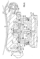
- the shoe press 10 includes a press shoe 12 which is configured on one surface 14 thereof so as to be generally complementary in contour to a backing member such as the counter roll 16 depicted in the drawings.
- the shoe 12 and counter roll 16 define a nip N through which a moving web W of paper, paperboard, or the like is carried.
- the web W typically is carried by an endless belt B and is in contact with one or more press felts F or other absorbent material.
- the shoe press 10 can be used in the press section and/or calender of a papermaking machine, and can also be used as a prepress in a forming section of a papermaking machine. It will be recognized that when used in a calender or forming section of a machine, the web W would be passed through the device 10 without any absorbent felt.
- the shoe press 10 further includes a support 18 .
- the shoe 12 and the support 18 extend lengthwise in the cross-machine direction (as best seen in FIG. 3) along at least the full width of the web W , and preferably the shoe 12 is slightly wider than the web W .
- the shoe 12 is supported by the support 18 and is urged toward the backing member 16 for applying pressure to the web W by a plurality of articulated hydraulic loading cylinders 20 arranged between the support 18 and the shoe 12 and spaced apart in the cross-machine direction.
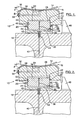
- Each loading cylinder 20 comprises a piston member and a cylinder member, one of the members being formed in two parts and the other member forming a coupler between the two parts. More particularly, the two-piece member of the loading cylinder 20 includes a first cylinder 22 that is fixed relative to the shoe 12 , a second cylinder 24 that is fixed relative to the support 18 , and a piston 26 slidably received with each of the cylinders.
- the first cylinder 22 comprises a recess formed in the shoe 12 .
- the second cylinder 24 is a member formed separately from the support 18 and affixed thereto.
- a first end 28 of the piston 26 is slidably received within the first cylinder 22 and a second end 30 of the piston is slidably received within the second cylinder 24.
- a resilient compressible seal 32 surrounds each end of the piston 26 for sealing against the inner surfaces of the cylinders.
- a first working chamber 34 is thus defined between the first end 28 of the piston 26 and the side and end walls of the first cylinder 22
- a second working chamber 36 is defined between the second end 30 of the piston and the side and end walls of the second cylinder 24 .
- the piston 26 includes a passage 38 connecting the first and second working chambers so that there is fluid communication between them.
- the support 18 includes a supply passage 40 for supplying pressurized hydraulic fluid into the second working chamber 36 .
- the supply passage 40 connects with a bore 42 in a fastener 44 which is used for securing the second cylinder 24 to the support 18 .
- pressurized fluid supplied through the passage 40 into the second working chamber 36 causes the first and second cylinders 22 and 24 to be urged away from each other.
- the shoe 12 is thus urged toward the backing member 16.
- the first working chamber 34 is also pressurized substantially equal to the second chamber by virtue of the passage 38 in the piston 26 . Where the first and second ends 28 and 30 of the piston are essentially equal as shown in FIGS. 1-3, the net axial force on the piston 26 is thus nearly zero.
- the piston 26 preferably includes spherical surfaces 46 which confront the inner surfaces of the cylinders 22 and 24 .
- the resilient compressible seals 32 extend radially outward of the spherical surfaces 46 into contact with the inner surfaces of the cylinders. Accordingly, the piston 26 is able to pivot about axes parallel to the machine and cross-machine directions relative to both of the cylinders while maintaining proper sealing of the working chambers.
- FIG. 2 depicts the shoe 12 and first cylinder 22 pivoted relative to the piston 26 about an axis parallel to the cross-machine direction. Although only one of the loading cylinders 20 is depicted in FIG.
- FIG. 3 depicts a pair of the loading cylinders 20 in which the pistons 26 have been pivoted relative to both cylinders 22 and 24 about axes parallel to the machine direction as a result of the shoe 12 being translated in the cross-machine direction (to the left in FIG. 3).
- the loading cylinders 20 allow substantial freedom of movement of the shoe 12 in terms of both pivotal and translational movements.
- the shoe press includes a guide rail or stop 48 for limiting the extent to which the shoe can move.
- the loading cylinders 20 also include stop rings 50 for limiting the movement of the pistons 26 in the loading direction away from the support 18.
- the stop rings 50 are affixed to the outermost ends of the second cylinders 24 and extend radially inward to a diameter smaller than that of the spherical surfaces 46 on the second ends of the pistons 26 .
- Each piston 26 has an axially extending portion 52 of reduced diameter located about midway along the axial length of the piston between the spherical surfaces 46 at each end.
- the reduced diameter portion 52 is smaller in diameter than the inner surface of the stop ring 50 over a sufficient axial length of the piston 26 so that the piston is capable of some range of axial movement within the second cylinder 24.
- the shoe press 10 also includes hydrostatic compartments 54 in the surface 14 facing the counter roll 16 for lubrication purposes, as well known in the art.
- the compartments 54 are supplied with hydraulic fluid by a pipe 5 6 attached to the shoe 12 and communicating with the compartments via passages 58 in the shoe.
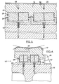
- FIG. 4 depicts a second preferred embodiment of the invention in the form of a shoe press 10 ' having two rows of loading cylinders 20 ' generally as described above (the primary differences being the smaller diameters of the loading cylinders 20 '), the two rows being spaced apart in the machine direction for varying the nip pressure in the machine direction.
- FIG. 5 illustrates a third preferred embodiment of the invention.
- the shoe press 110 of FIG. 5 includes loading cylinders 120 in which the first cylinders 122 are formed not as recesses in the shoe 112 but rather as separate members, similar to the second cylinders 124 .
- Hydraulic fluid is supplied to the loading cylinders 120 through passages 140 in the shoe 112 and through openings 142 in the first cylinders 122 .
- the passages 140 may be supplied with fluid via a pipe (not shown) attached to the shoe 112 in a manner similar to that depicted in FIGS. 1-2. It will also be noted that FIG.
- FIG. 5 illustrates the type of deformation of the shoe 112 caused by thermal expansion, whereby the two loading cylinders 120 on the left-hand side which are located on one side of the machine axial centerline have their pistons 126 pivoted in one direction about axes parallel to the machine direction, and the two loading cylinders 120 on the right-hand side of the centerline have their pistons 126 pivoted in the opposite direction about axes parallel to the machine direction.
- the pistons 126 are hollow tubular members, as opposed to the generally solid pistons 26 and 26 ' of the presses shown in FIGS. 1-4. This construction of the pistons 126 results in savings in material relative to the solid-type pistons.
- FIG. 6 depicts a fourth preferred embodiment of the invention.
- the shoe press 110 ' of FIG. 6 employs loading cylinders 120' in which the two-piece member is the piston and the coupler is the cylinder.
- the loading cylinder 120 ' comprises a first piston 126a affixed to the shoe 112' , and second piston 126b affixed to the support 118' , and a cylinder 122' within which both pistons are slidably received.
- a common working chamber 134' is defined between the pistons 126a and 126b .
- Pressurized fluid is supplied to the working chamber 134' by a passage 140 ' in the support 118' which connects with a passage 142' that extends through a fastener 144' which secures the second piston 126b to the support 118'.
- a ring 50' similar in function to the ring 50 of FIG. 1, is affixed to the end of the cylinder 122' adjacent the shoe 112 ' for preventing the first piston 126a from being withdrawn from the cylinder 122' .
- FIG. 7 depicts a fifth preferred embodiment of the invention.
- the shoe press 210 of FIG. 7 includes hydraulic loading cylinders 220 in which the pistons 226 are formed as hollow tubular members, and the first cylinder 222 and second cylinder 224 are separate members affixed to the press shoe 212 and the support 218 , respectively.
- the first cylinder 222 has an end wall 223 which abuts the shoe 212 and a hollow tubular portion 225 projecting normally from the end wall 223 toward the second cylinder 224 .
- the second cylinder 224 has an end wall 227 which abuts the support 218 and a hollow tubular portion 229 projecting normally from the end wall 227 toward the first cylinder 222 .
- Each of the tubular portions 225 and 229 has a cylindrical inner surface.
- the piston 226 includes flanges 231 adjacent each end of the piston.
- the flanges 231 are generally annular and project radially outward beyond the cylindrical outer surface of the piston.
- the radially outermost surfaces 233 of the flanges 231 are preferably but not necessarily spherical.
- Each flange 231 includes a groove 235 continuously encircling the piston and housing a pair of resilient compressible seal rings 237a and 237b .
- the inner seal rings 237a are preferably rubber or a material having compressibility and resilience properties similar to rubber.
- the outer seal rings 237b which make contact with the inner surfaces of the cylinders are preferably made of a material somewhat stiffer than that of the inner seal rings.
- a suitable material is, for example, a polymer having bronze additives, although other materials may alternatively be used.
- the outer seal rings 237b project radially outward of the spherical surfaces 233 of the flanges and are larger in diameter than the inner surfaces of the cylinders 222, 224 in their undeformed conditions, such that there is an interference fit of the seal rings in the cylinders.
- the seal rings 237a and 237b therefore are compressed, and their resilience keeps them in sealing contact with the cylinders throughout the range of pivotal movement of the piston 226 .
- the lengths of the flanges 231 in the radially outward direction are sufficiently large in relation to the axial lengths of the flanges and the axial length between the two flanges so that the piston 226 is capable of pivoting over a relatively large angular range while maintain proper sealing contact of the seal rings 237b with the cylinders.
- the first cylinders 222 are affixed to the shoe 212 by a pair of clamps 239 and 241 adjacent the upstream and downstream sides, respectively, of the shoe.
- the clamps include ledges 243 which clamp an annular flange 245 of the first cylinder 222 between the shoe 212 and the ledges 243 .
- the holes 247 in the clamps 239 and 241 through which fasteners are passed for securing the clamps to the shoe are not identically located relative to the ledges 243 . This enables the clamps 239 and 241 to be interchanged so as to alter the location of the first cylinder 222 relative to the shoe 212 in the machine direction.
- the support 218 also includes an adjustment mechanism for moving the support and the second cylinder 224 in the machine direction.
- This adjustment mechanism may be, for example, a pair of clamps (not shown) similar to the clamps 239 and 241 for securing the support 218 to a frame structure, or alternatively, a pair of such clamps for securing the second cylinder 224 to the support 218 . Accordingly, the entire loading cylinder 220 can be shifted in the machine direction relative to the shoe 212 for changing the center of load on the shoe.
- the shoe press 210 includes features for limiting motion of the shoe 212 in the upstream, downstream, and cross-machine directions.
- a stop 48 is positioned adjacent the downstream side of the shoe 212 for limiting the extent of downstream motion of the shoe 212.
- a pin 49 is affixed to the downstream side of the shoe 212 and projects outward therefrom in the machine direction.
- the stop 48 includes a slot 51 into which the pin 49 extends.
- the pin 49 is located at a midpoint of the width of the shoe 212 in the cross-machine direction, as shown in FIG. 7A.
- the slot 51 extends in the loading direction so that the shoe 212 is free to move toward and away from the counter roll.
- the slot 51 is only slightly wider than the pin 49 , and accordingly, the shoe 212 is restrained from moving in the cross-machine direction. Furthermore, the pin 49 engaged in the slot 51 ensures that thermal expansion of the shoe 212 in the cross-machine direction does not all occur in a single direction but rather occurs in opposite directions on either side of the longitudinal centerline of the shoe press 210 .
- the shoe press 210 also includes pins 249 affixed to the opposite side edges of the shoe 212 and projecting outward therefrom in the cross-machine direction.
- a pair of stops 248 are positioned adjacent the opposite sides of the shoe 212 so that they can be abutted by the pins 249 when the shoe 212 moves in the upstream direction.
- the stops 248 and pins 249 limit the extent of shoe movement in the upstream direction, and also help prevent the shoe 212 from assuming a slanted position in which one side is further upstream than the other side. It will of course be appreciated that instead of the stops 248 and pins 249 , a single elongate stop (not shown) could be positioned adjacent the upstream edge of the shoe 212 so as to serve the same purposes as the stops 248 and pins 249 .
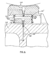
- FIG. 8 shows one of the loading cylinders 220' having a shoe-retracting actuator 260.
- the actuator 260 comprises an actuator piston 262 having a stem 264 secured to the support 218 and projecting normally therefrom toward the shoe 212 .
- An actuator cylinder 266 surrounds the actuator piston so as to define a working chamber 268 pressurizable with hydraulic fluid to cause the actuator cylinder 266 to be urged toward the support 218 .
- the stem 264 of the actuator piston includes a passage 270 for supplying fluid into the chamber 268
- the support 218 includes a fluid passage 272 which connects with the passage 270 in the stem.
- the chamber 268 is constantly pressurized during operation of the shoe press so that the pressure within the chamber 268 of the shoe-retracting actuator is not substantially less than that in the working chamber 234 of the loading cylinder 220' in order to avoid damage to the actuator.
- the press shoe 212 is to be retracted away from the counter roll, the pressure in the working chamber 234 is decreased below that in the chamber 268 .
- the actuator cylinder 266 at the end adjacent the shoe 212 includes an annular ring 274 which extends radially inward from the cylinder side wall.
- a projection 276 is affixed to the first cylinder 222' and extends through the central opening of the annular ring 274.
- the projection 276 includes a head 278 larger in diameter than the inner diameter of the ring 274 for engaging the annular ring 274 such that movement of the actuator cylinder 266 toward the support 218 causes the shoe 212 to be pulled toward the support.
- the annular ring 274 includes holes 275 for equalizing the pressure on both sides of the ring. To aid in disassembling the press, the annular ring 274 is removably threaded into the actuator cylinder 266 .
- the projection 276 is also removably threaded into the first cylinder 222 '.
- the first cylinder 222' includes a reinforced boss 280 into which the projection 276 is threaded.
- the shoe 212 includes a recess 282 for accommodating the boss 280 .
- the recess 282 is larger in diameter than the boss 280 so that the first cylinder 222 '. can be shifted in the machine direction by interchanging the clamps 239 and 241, as previously described.
- the shoe-retracting actuator 260 also enables a further advantage in addition to its function of retracting the shoe 212 . Specifically, if the hydraulic pressure within the chamber 268 of the actuator 260 is reduced below the pressure existing in the working chamber 234 , the net loading force exerted on the shoe 212 is increased above that exerted if the pressures are equal in the chambers 234 and 268. Accordingly, the actuator 260 can also be used to increase the loading capacity of a loading cylinder without increasing the size of the loading cylinder.
- FIG. 9 shows a sixth preferred embodiment of a loading cylinder 320 in accordance with the invention.
- the loading cylinder 320 includes a first cylinder 322 which has a thickened end wall 323 which mounts the projection 276 of the shoe-retracting actuator 260' , and accordingly the shoe 312 does not require a recess for accommodating the projection 276 .
- the first cylinder 322 can be shifted in the machine direction by interchanging the clamps 239 and 241 , as described above for the loading cylinder 220' .
- the second cylinder 324 can be shifted in the machine direction in a similar manner.
- the support 318 includes a recess 319 and the second cylinder 324 includes an end wall 325 upon which the stem 264' of the actuator piston 262' is affixed.
- the stem 264' extends through a thickened portion 326 of the cylinder end wall 325 , and the thickened portion 326 and a part of the stem 264' extend into the recess 319 in the support 318 .
- the recess 319 in the support 318 is wider in the machine direction than the thickened portion 326 of the second cylinder 324 so that the second cylinder 324 can be shifted in the machine direction.
- the second cylinder 324 is secured on the support 318 by a pair of asymmetric clamps 339 and 341 in similar manner to the attachment of the first cylinder 322 to the shoe 312 by clamps 239 and 241 .
- the second cylinder 324 is shifted in the machine direction by interchanging the clamps 339 and 341.
- Pressurized hydraulic fluid is supplied to the shoe-retracting actuator 260' by a flexible hose 342 which connects to an end 328 of the stem 264' projecting from the thickened portion 326 of the second cylinder end wall 325.
- This manner of making the fluid connection with the actuator piston 262' facilitates shifting the second cylinder 324 and the actuator 260' in the machine direction.
- the invention provides a unique shoe press having significant advantages over prior presses, including the ability to tolerate deformations such as thermal expansion of the shoe without binding or malfunctioning of the loading cylinders.
- the invention also provides a simple mechanism for adjusting the center of load on the shoe in the machine direction.
Landscapes
- Paper (AREA)
Applications Claiming Priority (4)
| Application Number | Priority Date | Filing Date | Title |
|---|---|---|---|
| SE9800262A SE511256C2 (sv) | 1998-01-30 | 1998-01-30 | Skopress |
| SE9800262 | 1998-01-30 | ||
| US183924 | 1998-10-30 | ||
| US09/183,924 US6083352A (en) | 1998-01-30 | 1998-10-30 | Shoe press |
Publications (3)
| Publication Number | Publication Date |
|---|---|
| EP0933471A2 true EP0933471A2 (fr) | 1999-08-04 |
| EP0933471A3 EP0933471A3 (fr) | 1999-08-18 |
| EP0933471B1 EP0933471B1 (fr) | 2003-03-26 |
Family
ID=26663202
Family Applications (1)
| Application Number | Title | Priority Date | Filing Date |
|---|---|---|---|
| EP99850014A Revoked EP0933471B1 (fr) | 1998-01-30 | 1999-01-29 | Presse à patin |
Country Status (5)
| Country | Link |
|---|---|
| EP (1) | EP0933471B1 (fr) |
| JP (1) | JPH11279976A (fr) |
| AT (2) | AT3188U1 (fr) |
| CA (1) | CA2259768C (fr) |
| DE (2) | DE29900914U1 (fr) |
Cited By (6)
| Publication number | Priority date | Publication date | Assignee | Title |
|---|---|---|---|---|
| WO2001042559A1 (fr) * | 1999-12-10 | 2001-06-14 | Metso Paper Inc. | Presse presentant un large espace de pressage servant au pressage d'une bande de carton en mouvement |
| WO2001063043A1 (fr) * | 2000-02-18 | 2001-08-30 | Metso Paper Karlstad Ab | Presse presentant un large espace pour le pressage d'une bande de papier ou de carton en mouvement |
| EP1273700A1 (fr) * | 2001-07-05 | 2003-01-08 | Vaahto OY | Presse à pince allongée |
| WO2008092868A1 (fr) * | 2007-01-30 | 2008-08-07 | Gapcon Gmbh | Dispositif de charge pour un rouleau de presse à sabot |
| DE10196358B4 (de) * | 2000-06-19 | 2011-03-10 | Metso Paper, Inc. | Langspaltpresse für eine Papiermaschine oder Kartonmaschine |
| CN103774483A (zh) * | 2012-10-19 | 2014-05-07 | 美卓造纸机械公司 | 靴辊、长压区压榨装置和纤维幅材机 |
Families Citing this family (3)
| Publication number | Priority date | Publication date | Assignee | Title |
|---|---|---|---|---|
| SE516410C2 (sv) * | 2000-05-29 | 2002-01-15 | Valmet Karlstad Ab | Press i en maskin för framställning av en kontinuerligt löpande bana av cellulosahaltigt fibermaterial och förfarande för att förändra tryckprofilen i en sådan press |
| EP1605096B1 (fr) * | 2004-06-11 | 2007-09-05 | Metso Paper, Inc. | Presse à patin |
| SE545633C2 (en) * | 2020-12-07 | 2023-11-21 | Valmet Oy | A method for manufacturing a support body arrangement, and a support body arrangement |
Family Cites Families (2)
| Publication number | Priority date | Publication date | Assignee | Title |
|---|---|---|---|---|
| DE4423212C1 (de) * | 1994-07-01 | 1996-03-07 | Escher Wyss Gmbh | Walzenanordnung |
| DE19515832C1 (de) * | 1995-04-29 | 1996-05-02 | Voith Sulzer Papiermasch Gmbh | Schuhpreßwalze für eine Papiermaschine |
-
1999
- 1999-01-20 DE DE29900914U patent/DE29900914U1/de not_active Expired - Lifetime
- 1999-01-20 CA CA002259768A patent/CA2259768C/fr not_active Expired - Fee Related
- 1999-01-29 DE DE69906167T patent/DE69906167T2/de not_active Revoked
- 1999-01-29 AT AT0006399U patent/AT3188U1/de not_active IP Right Cessation
- 1999-01-29 EP EP99850014A patent/EP0933471B1/fr not_active Revoked
- 1999-01-29 AT AT99850014T patent/ATE235598T1/de active
- 1999-02-01 JP JP11024347A patent/JPH11279976A/ja active Pending
Cited By (8)
| Publication number | Priority date | Publication date | Assignee | Title |
|---|---|---|---|---|
| WO2001042559A1 (fr) * | 1999-12-10 | 2001-06-14 | Metso Paper Inc. | Presse presentant un large espace de pressage servant au pressage d'une bande de carton en mouvement |
| WO2001063043A1 (fr) * | 2000-02-18 | 2001-08-30 | Metso Paper Karlstad Ab | Presse presentant un large espace pour le pressage d'une bande de papier ou de carton en mouvement |
| DE10196358B4 (de) * | 2000-06-19 | 2011-03-10 | Metso Paper, Inc. | Langspaltpresse für eine Papiermaschine oder Kartonmaschine |
| EP1273700A1 (fr) * | 2001-07-05 | 2003-01-08 | Vaahto OY | Presse à pince allongée |
| WO2008092868A1 (fr) * | 2007-01-30 | 2008-08-07 | Gapcon Gmbh | Dispositif de charge pour un rouleau de presse à sabot |
| US8118980B2 (en) | 2007-01-30 | 2012-02-21 | Gapcon Gmbh | Loading device for a shoe press roll |
| CN103774483A (zh) * | 2012-10-19 | 2014-05-07 | 美卓造纸机械公司 | 靴辊、长压区压榨装置和纤维幅材机 |
| CN103774483B (zh) * | 2012-10-19 | 2017-03-29 | 维美德技术有限公司 | 靴辊、长压区压榨装置和纤维幅材机 |
Also Published As
| Publication number | Publication date |
|---|---|
| EP0933471B1 (fr) | 2003-03-26 |
| DE29900914U1 (de) | 1999-12-23 |
| EP0933471A3 (fr) | 1999-08-18 |
| AT3188U1 (de) | 1999-11-25 |
| DE69906167T2 (de) | 2003-12-11 |
| CA2259768C (fr) | 2004-05-11 |
| CA2259768A1 (fr) | 1999-07-30 |
| DE69906167D1 (de) | 2003-04-30 |
| JPH11279976A (ja) | 1999-10-12 |
| ATE235598T1 (de) | 2003-04-15 |
Similar Documents
| Publication | Publication Date | Title |
|---|---|---|
| US6083352A (en) | Shoe press | |
| CA1139140A (fr) | Rouleau de presse | |
| KR0169999B1 (ko) | 자동 부하형 편향 제어 로울 | |
| CA2259768C (fr) | Sabot de presse | |
| CA2538046C (fr) | Corps d'appui, dispositif de retenue, appareil equipe du corps d'appui pour le traitement d'une bande continue, procedes de creation d'un espacement allonge dans l'appareil et de regulation de charge dans l'espacement | |
| US5242361A (en) | Roller mechanism for axially locating the shell of a self-loading controlled deflection roll | |
| EP1605096B1 (fr) | Presse à patin | |
| CN113699821B (zh) | 衬套辊 | |
| US5733415A (en) | Closed shoe press head indexing system | |
| CA2152994A1 (fr) | Configuration de rouleau | |
| EP1238148B1 (fr) | Presse a pince allongee pour presser une bande de papier ou de carton en mouvement | |
| US6387219B2 (en) | Press device having an extended press nip for pressing a traveling paper or paperboard web | |
| US6042694A (en) | Shoe press | |
| JPS6146598B2 (fr) | ||
| CA2152993A1 (fr) | Configuration de rouleau | |
| EP1240387B1 (fr) | Appareil et procede de pressage d'une bande de papier | |
| EP1266081A1 (fr) | Presse presentant un large espace pour le pressage d'une bande de papier ou de carton en mouvement | |
| US20020060031A1 (en) | Apparatus and method for mounting and dismantling a wear body in a paper making machine | |
| US20030015306A1 (en) | Extended-nip press | |
| EP1127186A1 (fr) | Appareil et procede servant a monter et a demonter un corps d'usure dans une machine a papier | |
| US6139691A (en) | Shoe press | |
| SE9800262L (sv) | Skopress |
Legal Events
| Date | Code | Title | Description |
|---|---|---|---|
| PUAI | Public reference made under article 153(3) epc to a published international application that has entered the european phase |
Free format text: ORIGINAL CODE: 0009012 |
|
| PUAL | Search report despatched |
Free format text: ORIGINAL CODE: 0009013 |
|
| AK | Designated contracting states |
Kind code of ref document: A2 Designated state(s): AT DE FI FR GB IT SE |
|
| AX | Request for extension of the european patent |
Free format text: AL;LT;LV;MK;RO;SI |
|
| AK | Designated contracting states |
Kind code of ref document: A3 Designated state(s): AT BE CH CY DE DK ES FI FR GB GR IE IT LI LU MC NL PT SE |
|
| AX | Request for extension of the european patent |
Free format text: AL;LT;LV;MK;RO;SI |
|
| 17P | Request for examination filed |
Effective date: 19991006 |
|
| AKX | Designation fees paid |
Free format text: AT DE FI FR GB IT SE |
|
| 17Q | First examination report despatched |
Effective date: 20011129 |
|
| GRAG | Despatch of communication of intention to grant |
Free format text: ORIGINAL CODE: EPIDOS AGRA |
|
| RTI1 | Title (correction) |
Free format text: SHOE PRESS |
|
| GRAG | Despatch of communication of intention to grant |
Free format text: ORIGINAL CODE: EPIDOS AGRA |
|
| GRAH | Despatch of communication of intention to grant a patent |
Free format text: ORIGINAL CODE: EPIDOS IGRA |
|
| RAP1 | Party data changed (applicant data changed or rights of an application transferred) |
Owner name: METSO PAPER INC. |
|
| GRAH | Despatch of communication of intention to grant a patent |
Free format text: ORIGINAL CODE: EPIDOS IGRA |
|
| GRAA | (expected) grant |
Free format text: ORIGINAL CODE: 0009210 |
|
| AK | Designated contracting states |
Designated state(s): AT DE FI FR GB IT SE |
|
| PG25 | Lapsed in a contracting state [announced via postgrant information from national office to epo] |
Ref country code: FR Free format text: LAPSE BECAUSE OF FAILURE TO SUBMIT A TRANSLATION OF THE DESCRIPTION OR TO PAY THE FEE WITHIN THE PRESCRIBED TIME-LIMIT Effective date: 20030326 |
|
| REG | Reference to a national code |
Ref country code: GB Ref legal event code: FG4D |
|
| REF | Corresponds to: |
Ref document number: 69906167 Country of ref document: DE Date of ref document: 20030430 Kind code of ref document: P |
|
| PG25 | Lapsed in a contracting state [announced via postgrant information from national office to epo] |
Ref country code: SE Free format text: LAPSE BECAUSE OF FAILURE TO SUBMIT A TRANSLATION OF THE DESCRIPTION OR TO PAY THE FEE WITHIN THE PRESCRIBED TIME-LIMIT Effective date: 20030626 |
|
| PLBQ | Unpublished change to opponent data |
Free format text: ORIGINAL CODE: EPIDOS OPPO |
|
| PLBI | Opposition filed |
Free format text: ORIGINAL CODE: 0009260 |
|
| PG25 | Lapsed in a contracting state [announced via postgrant information from national office to epo] |
Ref country code: GB Free format text: LAPSE BECAUSE OF NON-PAYMENT OF DUE FEES Effective date: 20040129 |
|
| PLAX | Notice of opposition and request to file observation + time limit sent |
Free format text: ORIGINAL CODE: EPIDOSNOBS2 |
|
| EN | Fr: translation not filed | ||
| 26 | Opposition filed |
Opponent name: EDUARD KUESTERSMASCHINENFABRIK GMBH & CO. KG Effective date: 20031223 |
|
| PLBB | Reply of patent proprietor to notice(s) of opposition received |
Free format text: ORIGINAL CODE: EPIDOSNOBS3 |
|
| GBPC | Gb: european patent ceased through non-payment of renewal fee |
Effective date: 20040129 |
|
| APBP | Date of receipt of notice of appeal recorded |
Free format text: ORIGINAL CODE: EPIDOSNNOA2O |
|
| APAH | Appeal reference modified |
Free format text: ORIGINAL CODE: EPIDOSCREFNO |
|
| APBQ | Date of receipt of statement of grounds of appeal recorded |
Free format text: ORIGINAL CODE: EPIDOSNNOA3O |
|
| PLAB | Opposition data, opponent's data or that of the opponent's representative modified |
Free format text: ORIGINAL CODE: 0009299OPPO |
|
| R26 | Opposition filed (corrected) |
Opponent name: ANDRITZ KUESTERS GMBH Effective date: 20031223 |
|
| PGFP | Annual fee paid to national office [announced via postgrant information from national office to epo] |
Ref country code: AT Payment date: 20090115 Year of fee payment: 11 |
|
| APBU | Appeal procedure closed |
Free format text: ORIGINAL CODE: EPIDOSNNOA9O |
|
| PGFP | Annual fee paid to national office [announced via postgrant information from national office to epo] |
Ref country code: FI Payment date: 20090115 Year of fee payment: 11 Ref country code: DE Payment date: 20090122 Year of fee payment: 11 |
|
| RDAF | Communication despatched that patent is revoked |
Free format text: ORIGINAL CODE: EPIDOSNREV1 |
|
| RDAG | Patent revoked |
Free format text: ORIGINAL CODE: 0009271 |
|
| STAA | Information on the status of an ep patent application or granted ep patent |
Free format text: STATUS: PATENT REVOKED |
|
| PGFP | Annual fee paid to national office [announced via postgrant information from national office to epo] |
Ref country code: IT Payment date: 20090128 Year of fee payment: 11 |
|
| 27W | Patent revoked |
Effective date: 20090506 |