EP0933542B2 - Verfahren zur Festlegung einer Lagerschale eines Kugelgelenks - Google Patents
Verfahren zur Festlegung einer Lagerschale eines Kugelgelenks Download PDFInfo
- Publication number
- EP0933542B2 EP0933542B2 EP99100296A EP99100296A EP0933542B2 EP 0933542 B2 EP0933542 B2 EP 0933542B2 EP 99100296 A EP99100296 A EP 99100296A EP 99100296 A EP99100296 A EP 99100296A EP 0933542 B2 EP0933542 B2 EP 0933542B2
- Authority
- EP
- European Patent Office
- Prior art keywords
- collar
- bearing shell
- tool
- component
- ball joint
- Prior art date
- Legal status (The legal status is an assumption and is not a legal conclusion. Google has not performed a legal analysis and makes no representation as to the accuracy of the status listed.)
- Expired - Lifetime
Links
- 238000000034 method Methods 0.000 title claims description 13
- 239000011257 shell material Substances 0.000 description 30
- 238000010438 heat treatment Methods 0.000 description 9
- 239000000463 material Substances 0.000 description 5
- 238000002844 melting Methods 0.000 description 4
- 230000008018 melting Effects 0.000 description 4
- 238000006243 chemical reaction Methods 0.000 description 1
- 230000001419 dependent effect Effects 0.000 description 1
- 238000003780 insertion Methods 0.000 description 1
- 230000037431 insertion Effects 0.000 description 1
- 230000009466 transformation Effects 0.000 description 1
- 230000001131 transforming effect Effects 0.000 description 1
- 238000002604 ultrasonography Methods 0.000 description 1
Images
Classifications
-
- B—PERFORMING OPERATIONS; TRANSPORTING
- B29—WORKING OF PLASTICS; WORKING OF SUBSTANCES IN A PLASTIC STATE IN GENERAL
- B29C—SHAPING OR JOINING OF PLASTICS; SHAPING OF MATERIAL IN A PLASTIC STATE, NOT OTHERWISE PROVIDED FOR; AFTER-TREATMENT OF THE SHAPED PRODUCTS, e.g. REPAIRING
- B29C66/00—General aspects of processes or apparatus for joining preformed parts
- B29C66/40—General aspects of joining substantially flat articles, e.g. plates, sheets or web-like materials; Making flat seams in tubular or hollow articles; Joining single elements to substantially flat surfaces
- B29C66/47—Joining single elements to sheets, plates or other substantially flat surfaces
- B29C66/474—Joining single elements to sheets, plates or other substantially flat surfaces said single elements being substantially non-flat
-
- B—PERFORMING OPERATIONS; TRANSPORTING
- B29—WORKING OF PLASTICS; WORKING OF SUBSTANCES IN A PLASTIC STATE IN GENERAL
- B29C—SHAPING OR JOINING OF PLASTICS; SHAPING OF MATERIAL IN A PLASTIC STATE, NOT OTHERWISE PROVIDED FOR; AFTER-TREATMENT OF THE SHAPED PRODUCTS, e.g. REPAIRING
- B29C57/00—Shaping of tube ends, e.g. flanging, belling or closing; Apparatus therefor, e.g. collapsible mandrels
- B29C57/12—Rim rolling
-
- B—PERFORMING OPERATIONS; TRANSPORTING
- B29—WORKING OF PLASTICS; WORKING OF SUBSTANCES IN A PLASTIC STATE IN GENERAL
- B29C—SHAPING OR JOINING OF PLASTICS; SHAPING OF MATERIAL IN A PLASTIC STATE, NOT OTHERWISE PROVIDED FOR; AFTER-TREATMENT OF THE SHAPED PRODUCTS, e.g. REPAIRING
- B29C65/00—Joining or sealing of preformed parts, e.g. welding of plastics materials; Apparatus therefor
- B29C65/56—Joining or sealing of preformed parts, e.g. welding of plastics materials; Apparatus therefor using mechanical means or mechanical connections, e.g. form-fits
- B29C65/567—Joining or sealing of preformed parts, e.g. welding of plastics materials; Apparatus therefor using mechanical means or mechanical connections, e.g. form-fits using a tamping or a swaging operation, i.e. at least partially deforming the edge or the rim of a first part to be joined to clamp a second part to be joined
- B29C65/568—Joining or sealing of preformed parts, e.g. welding of plastics materials; Apparatus therefor using mechanical means or mechanical connections, e.g. form-fits using a tamping or a swaging operation, i.e. at least partially deforming the edge or the rim of a first part to be joined to clamp a second part to be joined using a swaging operation, i.e. totally deforming the edge or the rim of a first part to be joined to clamp a second part to be joined
-
- B—PERFORMING OPERATIONS; TRANSPORTING
- B29—WORKING OF PLASTICS; WORKING OF SUBSTANCES IN A PLASTIC STATE IN GENERAL
- B29C—SHAPING OR JOINING OF PLASTICS; SHAPING OF MATERIAL IN A PLASTIC STATE, NOT OTHERWISE PROVIDED FOR; AFTER-TREATMENT OF THE SHAPED PRODUCTS, e.g. REPAIRING
- B29C66/00—General aspects of processes or apparatus for joining preformed parts
- B29C66/50—General aspects of joining tubular articles; General aspects of joining long products, i.e. bars or profiled elements; General aspects of joining single elements to tubular articles, hollow articles or bars; General aspects of joining several hollow-preforms to form hollow or tubular articles
- B29C66/51—Joining tubular articles, profiled elements or bars; Joining single elements to tubular articles, hollow articles or bars; Joining several hollow-preforms to form hollow or tubular articles
- B29C66/53—Joining single elements to tubular articles, hollow articles or bars
- B29C66/532—Joining single elements to the wall of tubular articles, hollow articles or bars
- B29C66/5324—Joining single elements to the wall of tubular articles, hollow articles or bars said single elements being substantially annular, i.e. of finite length
- B29C66/53245—Joining single elements to the wall of tubular articles, hollow articles or bars said single elements being substantially annular, i.e. of finite length said articles being hollow
-
- B—PERFORMING OPERATIONS; TRANSPORTING
- B29—WORKING OF PLASTICS; WORKING OF SUBSTANCES IN A PLASTIC STATE IN GENERAL
- B29C—SHAPING OR JOINING OF PLASTICS; SHAPING OF MATERIAL IN A PLASTIC STATE, NOT OTHERWISE PROVIDED FOR; AFTER-TREATMENT OF THE SHAPED PRODUCTS, e.g. REPAIRING
- B29C66/00—General aspects of processes or apparatus for joining preformed parts
- B29C66/50—General aspects of joining tubular articles; General aspects of joining long products, i.e. bars or profiled elements; General aspects of joining single elements to tubular articles, hollow articles or bars; General aspects of joining several hollow-preforms to form hollow or tubular articles
- B29C66/61—Joining from or joining on the inside
-
- B—PERFORMING OPERATIONS; TRANSPORTING
- B29—WORKING OF PLASTICS; WORKING OF SUBSTANCES IN A PLASTIC STATE IN GENERAL
- B29C—SHAPING OR JOINING OF PLASTICS; SHAPING OF MATERIAL IN A PLASTIC STATE, NOT OTHERWISE PROVIDED FOR; AFTER-TREATMENT OF THE SHAPED PRODUCTS, e.g. REPAIRING
- B29C66/00—General aspects of processes or apparatus for joining preformed parts
- B29C66/80—General aspects of machine operations or constructions and parts thereof
- B29C66/81—General aspects of the pressing elements, i.e. the elements applying pressure on the parts to be joined in the area to be joined, e.g. the welding jaws or clamps
- B29C66/814—General aspects of the pressing elements, i.e. the elements applying pressure on the parts to be joined in the area to be joined, e.g. the welding jaws or clamps characterised by the design of the pressing elements, e.g. of the welding jaws or clamps
- B29C66/8141—General aspects of the pressing elements, i.e. the elements applying pressure on the parts to be joined in the area to be joined, e.g. the welding jaws or clamps characterised by the design of the pressing elements, e.g. of the welding jaws or clamps characterised by the surface geometry of the part of the pressing elements, e.g. welding jaws or clamps, coming into contact with the parts to be joined
- B29C66/81411—General aspects of the pressing elements, i.e. the elements applying pressure on the parts to be joined in the area to be joined, e.g. the welding jaws or clamps characterised by the design of the pressing elements, e.g. of the welding jaws or clamps characterised by the surface geometry of the part of the pressing elements, e.g. welding jaws or clamps, coming into contact with the parts to be joined characterised by its cross-section, e.g. transversal or longitudinal, being non-flat
- B29C66/81413—General aspects of the pressing elements, i.e. the elements applying pressure on the parts to be joined in the area to be joined, e.g. the welding jaws or clamps characterised by the design of the pressing elements, e.g. of the welding jaws or clamps characterised by the surface geometry of the part of the pressing elements, e.g. welding jaws or clamps, coming into contact with the parts to be joined characterised by its cross-section, e.g. transversal or longitudinal, being non-flat being non-symmetrical
-
- B—PERFORMING OPERATIONS; TRANSPORTING
- B29—WORKING OF PLASTICS; WORKING OF SUBSTANCES IN A PLASTIC STATE IN GENERAL
- B29C—SHAPING OR JOINING OF PLASTICS; SHAPING OF MATERIAL IN A PLASTIC STATE, NOT OTHERWISE PROVIDED FOR; AFTER-TREATMENT OF THE SHAPED PRODUCTS, e.g. REPAIRING
- B29C66/00—General aspects of processes or apparatus for joining preformed parts
- B29C66/80—General aspects of machine operations or constructions and parts thereof
- B29C66/81—General aspects of the pressing elements, i.e. the elements applying pressure on the parts to be joined in the area to be joined, e.g. the welding jaws or clamps
- B29C66/814—General aspects of the pressing elements, i.e. the elements applying pressure on the parts to be joined in the area to be joined, e.g. the welding jaws or clamps characterised by the design of the pressing elements, e.g. of the welding jaws or clamps
- B29C66/8141—General aspects of the pressing elements, i.e. the elements applying pressure on the parts to be joined in the area to be joined, e.g. the welding jaws or clamps characterised by the design of the pressing elements, e.g. of the welding jaws or clamps characterised by the surface geometry of the part of the pressing elements, e.g. welding jaws or clamps, coming into contact with the parts to be joined
- B29C66/81431—General aspects of the pressing elements, i.e. the elements applying pressure on the parts to be joined in the area to be joined, e.g. the welding jaws or clamps characterised by the design of the pressing elements, e.g. of the welding jaws or clamps characterised by the surface geometry of the part of the pressing elements, e.g. welding jaws or clamps, coming into contact with the parts to be joined comprising a single cavity, e.g. a groove
-
- B—PERFORMING OPERATIONS; TRANSPORTING
- B29—WORKING OF PLASTICS; WORKING OF SUBSTANCES IN A PLASTIC STATE IN GENERAL
- B29C—SHAPING OR JOINING OF PLASTICS; SHAPING OF MATERIAL IN A PLASTIC STATE, NOT OTHERWISE PROVIDED FOR; AFTER-TREATMENT OF THE SHAPED PRODUCTS, e.g. REPAIRING
- B29C66/00—General aspects of processes or apparatus for joining preformed parts
- B29C66/80—General aspects of machine operations or constructions and parts thereof
- B29C66/83—General aspects of machine operations or constructions and parts thereof characterised by the movement of the joining or pressing tools
- B29C66/832—Reciprocating joining or pressing tools
- B29C66/8322—Joining or pressing tools reciprocating along one axis
-
- F—MECHANICAL ENGINEERING; LIGHTING; HEATING; WEAPONS; BLASTING
- F16—ENGINEERING ELEMENTS AND UNITS; GENERAL MEASURES FOR PRODUCING AND MAINTAINING EFFECTIVE FUNCTIONING OF MACHINES OR INSTALLATIONS; THERMAL INSULATION IN GENERAL
- F16C—SHAFTS; FLEXIBLE SHAFTS; ELEMENTS OR CRANKSHAFT MECHANISMS; ROTARY BODIES OTHER THAN GEARING ELEMENTS; BEARINGS
- F16C11/00—Pivots; Pivotal connections
- F16C11/04—Pivotal connections
- F16C11/06—Ball-joints; Other joints having more than one degree of angular freedom, i.e. universal joints
- F16C11/0619—Ball-joints; Other joints having more than one degree of angular freedom, i.e. universal joints the female part comprising a blind socket receiving the male part
- F16C11/0623—Construction or details of the socket member
- F16C11/0628—Construction or details of the socket member with linings
- F16C11/0633—Construction or details of the socket member with linings the linings being made of plastics
- F16C11/0638—Construction or details of the socket member with linings the linings being made of plastics characterised by geometrical details
-
- F—MECHANICAL ENGINEERING; LIGHTING; HEATING; WEAPONS; BLASTING
- F16—ENGINEERING ELEMENTS AND UNITS; GENERAL MEASURES FOR PRODUCING AND MAINTAINING EFFECTIVE FUNCTIONING OF MACHINES OR INSTALLATIONS; THERMAL INSULATION IN GENERAL
- F16C—SHAFTS; FLEXIBLE SHAFTS; ELEMENTS OR CRANKSHAFT MECHANISMS; ROTARY BODIES OTHER THAN GEARING ELEMENTS; BEARINGS
- F16C11/00—Pivots; Pivotal connections
- F16C11/04—Pivotal connections
- F16C11/06—Ball-joints; Other joints having more than one degree of angular freedom, i.e. universal joints
- F16C11/0685—Manufacture of ball-joints and parts thereof, e.g. assembly of ball-joints
-
- F—MECHANICAL ENGINEERING; LIGHTING; HEATING; WEAPONS; BLASTING
- F16—ENGINEERING ELEMENTS AND UNITS; GENERAL MEASURES FOR PRODUCING AND MAINTAINING EFFECTIVE FUNCTIONING OF MACHINES OR INSTALLATIONS; THERMAL INSULATION IN GENERAL
- F16C—SHAFTS; FLEXIBLE SHAFTS; ELEMENTS OR CRANKSHAFT MECHANISMS; ROTARY BODIES OTHER THAN GEARING ELEMENTS; BEARINGS
- F16C11/00—Pivots; Pivotal connections
- F16C11/04—Pivotal connections
- F16C11/06—Ball-joints; Other joints having more than one degree of angular freedom, i.e. universal joints
- F16C11/0695—Mounting of ball-joints, e.g. fixing them to a connecting rod
-
- B—PERFORMING OPERATIONS; TRANSPORTING
- B29—WORKING OF PLASTICS; WORKING OF SUBSTANCES IN A PLASTIC STATE IN GENERAL
- B29C—SHAPING OR JOINING OF PLASTICS; SHAPING OF MATERIAL IN A PLASTIC STATE, NOT OTHERWISE PROVIDED FOR; AFTER-TREATMENT OF THE SHAPED PRODUCTS, e.g. REPAIRING
- B29C53/00—Shaping by bending, folding, twisting, straightening or flattening; Apparatus therefor
- B29C53/34—Rim rolling
-
- B—PERFORMING OPERATIONS; TRANSPORTING
- B29—WORKING OF PLASTICS; WORKING OF SUBSTANCES IN A PLASTIC STATE IN GENERAL
- B29C—SHAPING OR JOINING OF PLASTICS; SHAPING OF MATERIAL IN A PLASTIC STATE, NOT OTHERWISE PROVIDED FOR; AFTER-TREATMENT OF THE SHAPED PRODUCTS, e.g. REPAIRING
- B29C66/00—General aspects of processes or apparatus for joining preformed parts
- B29C66/01—General aspects dealing with the joint area or with the area to be joined
- B29C66/05—Particular design of joint configurations
- B29C66/10—Particular design of joint configurations particular design of the joint cross-sections
- B29C66/11—Joint cross-sections comprising a single joint-segment, i.e. one of the parts to be joined comprising a single joint-segment in the joint cross-section
- B29C66/112—Single lapped joints
-
- B—PERFORMING OPERATIONS; TRANSPORTING
- B29—WORKING OF PLASTICS; WORKING OF SUBSTANCES IN A PLASTIC STATE IN GENERAL
- B29C—SHAPING OR JOINING OF PLASTICS; SHAPING OF MATERIAL IN A PLASTIC STATE, NOT OTHERWISE PROVIDED FOR; AFTER-TREATMENT OF THE SHAPED PRODUCTS, e.g. REPAIRING
- B29C66/00—General aspects of processes or apparatus for joining preformed parts
- B29C66/01—General aspects dealing with the joint area or with the area to be joined
- B29C66/05—Particular design of joint configurations
- B29C66/10—Particular design of joint configurations particular design of the joint cross-sections
- B29C66/13—Single flanged joints; Fin-type joints; Single hem joints; Edge joints; Interpenetrating fingered joints; Other specific particular designs of joint cross-sections not provided for in groups B29C66/11 - B29C66/12
- B29C66/135—Single hemmed joints, i.e. one of the parts to be joined being hemmed in the joint area
-
- B—PERFORMING OPERATIONS; TRANSPORTING
- B29—WORKING OF PLASTICS; WORKING OF SUBSTANCES IN A PLASTIC STATE IN GENERAL
- B29C—SHAPING OR JOINING OF PLASTICS; SHAPING OF MATERIAL IN A PLASTIC STATE, NOT OTHERWISE PROVIDED FOR; AFTER-TREATMENT OF THE SHAPED PRODUCTS, e.g. REPAIRING
- B29C66/00—General aspects of processes or apparatus for joining preformed parts
- B29C66/80—General aspects of machine operations or constructions and parts thereof
- B29C66/81—General aspects of the pressing elements, i.e. the elements applying pressure on the parts to be joined in the area to be joined, e.g. the welding jaws or clamps
- B29C66/814—General aspects of the pressing elements, i.e. the elements applying pressure on the parts to be joined in the area to be joined, e.g. the welding jaws or clamps characterised by the design of the pressing elements, e.g. of the welding jaws or clamps
- B29C66/8141—General aspects of the pressing elements, i.e. the elements applying pressure on the parts to be joined in the area to be joined, e.g. the welding jaws or clamps characterised by the design of the pressing elements, e.g. of the welding jaws or clamps characterised by the surface geometry of the part of the pressing elements, e.g. welding jaws or clamps, coming into contact with the parts to be joined
- B29C66/81411—General aspects of the pressing elements, i.e. the elements applying pressure on the parts to be joined in the area to be joined, e.g. the welding jaws or clamps characterised by the design of the pressing elements, e.g. of the welding jaws or clamps characterised by the surface geometry of the part of the pressing elements, e.g. welding jaws or clamps, coming into contact with the parts to be joined characterised by its cross-section, e.g. transversal or longitudinal, being non-flat
- B29C66/81421—General aspects of the pressing elements, i.e. the elements applying pressure on the parts to be joined in the area to be joined, e.g. the welding jaws or clamps characterised by the design of the pressing elements, e.g. of the welding jaws or clamps characterised by the surface geometry of the part of the pressing elements, e.g. welding jaws or clamps, coming into contact with the parts to be joined characterised by its cross-section, e.g. transversal or longitudinal, being non-flat being convex or concave
- B29C66/81423—General aspects of the pressing elements, i.e. the elements applying pressure on the parts to be joined in the area to be joined, e.g. the welding jaws or clamps characterised by the design of the pressing elements, e.g. of the welding jaws or clamps characterised by the surface geometry of the part of the pressing elements, e.g. welding jaws or clamps, coming into contact with the parts to be joined characterised by its cross-section, e.g. transversal or longitudinal, being non-flat being convex or concave being concave
-
- B—PERFORMING OPERATIONS; TRANSPORTING
- B29—WORKING OF PLASTICS; WORKING OF SUBSTANCES IN A PLASTIC STATE IN GENERAL
- B29L—INDEXING SCHEME ASSOCIATED WITH SUBCLASS B29C, RELATING TO PARTICULAR ARTICLES
- B29L2031/00—Other particular articles
- B29L2031/04—Bearings
-
- B—PERFORMING OPERATIONS; TRANSPORTING
- B29—WORKING OF PLASTICS; WORKING OF SUBSTANCES IN A PLASTIC STATE IN GENERAL
- B29L—INDEXING SCHEME ASSOCIATED WITH SUBCLASS B29C, RELATING TO PARTICULAR ARTICLES
- B29L2031/00—Other particular articles
- B29L2031/04—Bearings
- B29L2031/045—Bushes therefor
-
- B—PERFORMING OPERATIONS; TRANSPORTING
- B29—WORKING OF PLASTICS; WORKING OF SUBSTANCES IN A PLASTIC STATE IN GENERAL
- B29L—INDEXING SCHEME ASSOCIATED WITH SUBCLASS B29C, RELATING TO PARTICULAR ARTICLES
- B29L2031/00—Other particular articles
- B29L2031/737—Articles provided with holes, e.g. grids, sieves
Definitions
- the invention relates to a method for fixing an existing plastic bearing shell of a ball joint, in particular for motor vehicles, on a component which is provided with a continuous cylindrical receiving opening for the bearing shell, which rests on one side of the component with a stop surface and on the opposite side the component is determined by forming a protruding from the receiving opening, preferably annular collar.
- ball joints are known, whose provided with a ball joint ball pivotally and limited pivotally mounted in a plastic bearing shell, which in turn is arranged in a continuous cylindrical receiving opening of a component which forms, for example, in the manner of a joint housing that element the ball stud performs its relative movements.
- the ball joint receiving bearing shell made of plastic with a stop surface which rests positively on one side of the provided with the continuous cylindrical receiving opening member.
- the bearing shell is provided with a preferably annular collar, which protrudes from the receiving opening of the component after insertion of the bearing ball receiving the ball joint. By forming this projecting collar, the bearing shell is fixed to the component.
- the object underlying the invention is to further develop the known method described initially establishing a group consisting of plastic bearing shell of a ball joint to a component with the aim of further simplification and cost reduction.
- the reshaping of the invention formed on the bearing shell Federal requires neither a heating of the bearing shell to a critical, just below the melting point of the bearing shell material temperature, nor the use of expensive tools for ultrasonic forming.
- each desired heating of the reshaped federal which is not only dependent on the selected plastic material, but also of the respective cross-sectional shape of the federal.
- the tool used for forming the bearing shell collar will be formed according to the invention as a roller which rotates on the one hand about its own axis and at the same time on a corresponding shape of the shape of the federal transforming web is moved.
- the axial feed movement of the roller can be superimposed on a radial feed movement in order to bring about optimum deformation.
- the invention proposes forming the tool with an annular groove-shaped working surface which has a cross-section corresponding to the cross-section of the collar in the deformed state.
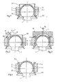
- the ball joint shown with reference to an exemplary embodiment comprises an integrally formed at the end of a ball stud 1 bearing ball 2, which is rotatably mounted and limited tiltable in a bearing shell 3 made of plastic.
- the bearing shell 3 is arranged in a continuous, cylindrical receiving opening 4.1 of a component 4, which also serves as a housing of the ball joint.
- the bearing shell 3 rests with an annular bearing surface 3.1 on the underside of the component 4.
- This contact surface 3.1 is formed by an enlarged diameter annular flange 3.2, which surrounds the opening of the bearing shell 3 and at the same time serves as a stop for the limitation of the pivot angle of the ball stud 1.
- this collar 3.3 of the bearing shell 3 is so transformed that it according to FIG. 4 at the contact surface 3.1 opposite side, d. H. 4 abuts in the embodiment at the top of the component 4, as shown in FIG.
- a tool W 1 is used, which is rotated about the longitudinal center axis L of the bearing shell 3 and thus of the ball joint and provided with a ringnutförmigen work surface A whose cross-section corresponds to that cross-section, the deformed collar 3.3 of FIG .. 4 Has.
- the material of the Federal 3.3 so that the collar 3.3 using the tool W 1 from the shape shown in Fig. 1 in the mold of FIG .. 4 can be transformed.
- the rotational speed and the feed rate of the tool W 1 the necessary for the forming process heating can be determined.
- the deformation of the collar 3.3 of the bearing shell 3 by means of a tool W 2 which is designed as a roll.
- this roller-shaped tool W 2 is formed with a ringnutförmigen work surface A, whose cross section corresponds to the cross section of the deformed collar 3.3 of FIG. 4.
- the roller-shaped tool W 2 rotates about its own axis R; at the same time, the tool W 2 is moved on a path corresponding to the shape of the collar 3.3 to be formed. In the embodiment, this is a circular path.
- the desired deformation of the originally cylindrical collar 3.3 into the final shape shown in FIG. 4 takes place through an axial infeed of the tool W 2 .
- the axial feed movement of the tool W 1 can in this case be superimposed on a radial feed movement.
- the method described above requires neither a heating of the bearing shell 3 or the collar 3.3 to a temperature just below the melting temperature of the plastic material, nor the use of high-precision and thus expensive sonotrodes for heating and forming by means of ultrasound.
Landscapes
- Engineering & Computer Science (AREA)
- Mechanical Engineering (AREA)
- General Engineering & Computer Science (AREA)
- Physics & Mathematics (AREA)
- Geometry (AREA)
- Rolling Contact Bearings (AREA)
- Pivots And Pivotal Connections (AREA)
- Lining Or Joining Of Plastics Or The Like (AREA)
- Mounting Of Bearings Or Others (AREA)
Description
- Die Erfindung betrifft ein Verfahren zur Festlegung einer aus Kunststoff bestehenden Lagerschale eines Kugelgelenks, insbesondere für Kraftfahrzeuge, an einem Bauteil, das mit einer durchgehenden zylindrischen Aufnahmeöffnung für die Lagerschale versehen ist, die an einer Seite des Bauteils mit einer Anschlagfläche anliegt und an der gegenüberliegenden Seite des Bauteils durch Umformen eines aus der Aufnahmeöffnung hervorstehenden, vorzugsweise ringförmigen Bundes festgelegt wird.
- Insbesondere für Kraftfahrzeuge sind Kugelgelenke bekannt, deren mit einer Gelenkkugel versehener Kugelzapfen verdrehbar und begrenzt schwenkbar in einer aus Kunststoff bestehenden Lagerschale gelagert ist, die ihrerseits in einer durchgehenden zylindrischen Aufnahmeöffnung eines Bauteils angeordnet ist, das beispielsweise in der Art eines Gelenkgehäuses dasjenige Element bildet, gegenüber dem der Kugelzapfen seine Relativbewegungen ausführt.
- Um unter Verwendung von möglichst wenig Bauteilen mit einfachem Aufbau ein preiswertes und in großen Serien montierbares Kugelgelenk zu schaffen, ist es aus der gattungsbildenden
DE 38 43 331 A1 bekannt, die die Gelenkkugel aufnehmende Lagerschale aus Kunststoff mit einer Anschlagfläche auszubilden, die an einer Seite des mit der durchgehenden zylindrischen Aufnahmeöffnung versehenen Bauteils formschlüssig anliegt. An der gegenüberliegenden Seite ist die Lagerschale mit einem vorzugsweise ringförmigen Bund versehen, der nach dem Einsetzen der die Gelenkkugel aufnehmenden Lagerschale aus der Aufnahmeöffnung des Bauteils hervorsteht. Durch Umformen dieses hervorstehenden Bundes wird die Lagerschale am Bauteil festgelegt. Bei dem aus derDE 38 43 331 A1 bekannten Verfahren erfolgt das Umformen des Bundes mittels eines in der Art einer Presse wirkenden Umformwerkzeuges, das in axialer Richtung der in eine Aufnahmevorrichtung eingesetzten Lagerschale bewegt wird und den zuvor erwärmten Bund bis zur Anlage am Bauteil umformt; die Erwärmung des Bundes erfolgt auf eine Temperatur, die etwa 5° unterhalb der Schmelztemperatur des für die Lagerschale verwendeten Kunststoffes liegt. - Da die Erwärmung der Lagerschale auf eine nur wenige Grade unterhalb der Schmelztemperatur des Kunststoffmaterials liegende Temperatur nicht nur mit einem zusätzlichen Energieaufwand verbunden ist, sondern insbesondere bei einer großseriellen Montage im Hinblick auf die Einhaltung enger Temperaturgrenzen mit nicht unerheblichen Risiken verbunden ist, wurde mit der
DE 43 06 006 A1 ein Verfahren vorgeschlagen, bei dem die Umformung des Bundes der Lagerschale ohne vorherige Erwärmung des Kunststoffmaterials durch Ultraschallverformung erfolgt. Dieses Verfahren vermeidet zwar den für die Erwärmung erforderlichen Energieeinsatz, hat jedoch den Nachteil, daß die für die Ultraschallverformung eingesetzten, formgebenden Werkzeuge sehr teuer sind, weil sie mit hoher Oberflächen-, Maß- und Formgenauigkeit hergestellt werden müssen. - Der Erfindung liegt die Aufgabe zugrunde, das bekannte, eingangs beschriebene Verfahren zur Festlegung einer aus Kunststoff bestehenden Lagerschale eines Kugelgelenks an einem Bauteil mit dem Ziel einer weiteren Vereinfachung und Kostenreduzierung weiterzuentwickeln.
- Die Lösung dieser Aufgabenstellung sieht die Merkmale des Anspruchs 1 vor.
- Die erfindungsgemäße Umformung des an der Lagerschale angeformten Bundes erfordert weder eine Erwärmung der Lagerschale auf eine kritische, nur knapp unterhalb des Schmelzpunktes des Lagerschalenmaterials liegende Temperatur, noch den Einsatz teurer Werkzeuge für eine Ultraschallumformung. Durch Wahl der Rotationsgeschwindigkeit des Werkzeuges und seiner axialen Zustellgeschwindigkeit läßt sich mit dem erfindungsgemäßen Verfahren die jeweils gewünschte Erwärmung des umzuformenden Bundes erzeugen, die nicht nur vom jeweils gewählten Kunststoffmaterial, sondern auch von der jeweiligen Querschnittsform des Bundes abhängig ist.
- Das zur Umformung des Lagerschalenbundes verwendete Werkzeug wird gemäß der Erfindung als Rolle ausgebildet sein, die einerseits um ihre eigene Achse rotiert und gleichzeitig auf einer der Form des umzuformenden Bundes entsprechenden Bahn bewegt wird. In diesem Fall kann der axialen Zustellbewegung der Rolle eine radiale Zustellbewegung überlagert werden, um eine optimale Verformung zu bewirken.
- Mit der Erfindung wird schließlich vorgeschlagen, das Werkzeug mit einer ringnutförmigen Arbeitsfläche auszubilden, die einen dem Querschnitt des Bundes im umgeformten Zustand entsprechenden Querschnitt aufweist.
- Auf der Zeichnung sind zwei Ausführungsbeispiele dargestellt, und zwar zeigen:
- Fig. 1
- einen Querschnitt durch ein Kugelgelenk vor der Umformung des Lagerschalenbundes,
- Fig. 2
- einen der Fig. 1 entsprechenden Querschnitt, bei dem der Lagerschalenbund mittels eines Ausführungsbeispiels umgeformt worden ist,
- Fig. 3
- einen den Fig. 1 und 2 entsprechenden Querschnitt, bei dem der Lagerschalenbund gemäß einem Ausführungsbeispiel des erfindungsgemäßen Verfahrens umgeformt worden ist, und
- Fig. 4
- einen weiteren Querschnitt durch das Kugelgelenk nach erfolgter Umformung des Lagerschalenbundes.
- Das anhand eines Ausführungsbeispiels dargestellte Kugelgelenk umfaßt eine am Ende eines Kugelzapfens 1 angeformte Lagerkugel 2, die in einer aus Kunststoff hergestellten Lagerschale 3 verdrehbar sowie begrenzt kippbar gelagert ist. Die Lagerschale 3 ist in einer durchgehenden, zylindrischen Aufnahmeöffnung 4.1 eines Bauteils 4 angeordnet, das zugleich als Gehäuse des Kugelgelenks dient.
- Die Lagerschale 3 liegt mit einer ringförmigen Anlagefläche 3.1 an der Unterseite des Bauteiles 4 an. Diese Anlagefläche 3.1 ist durch einen im Durchmesser vergrößerten Ringflansch 3.2 entstanden, der die Öffnung der Lagerschale 3 umgibt und zugleich als Anschlag für die Begrenzung des Verschwenkwinkels des Kugelzapfens 1 dient.
- An der gegenüberliegenden, beim Ausführungsbeispiel geschlossenen Seite der Lagerschale 3 ist diese mit einem ringförmigen Bund 3.3 versehen, der an der Oberseite des Bauteils 4 aus der zylindrischen Aufnahmeöffnung 4.1 herausragt. Um die Lagerschale 3 formschlüssig in der Aufnahmeöffnung 4.1 des Bauteils 4 zu halten, wird dieser Bund 3.3 der Lagerschale 3 derart umgeformt, daß er gemäß Fig. 4 an der der Anlagefläche 3.1 gegenüberliegenden Seite, d. h. beim Ausführungsbeispiel an der Oberseite des Bauteiles 4 anliegt, wie dies die Fig. 4 zeigt.
- Die Umformung des ursprünglich zylindrischen Bundes 3.1 der Lagerschale 3 erfolgt durch die axiale Zustellung eines rotierenden Werkzeuges, von dem auf der Zeichnung zwei Ausführungsbeispiele dargestellt sind.
- Beim Ausführungsbeispiel nach Fig. 2 wird ein Werkzeug W1 verwendet, das um die Längsmittelachse L der Lagerschale 3 und damit des Kugelgelenks rotiert und mit einer ringnutförmigen Arbeitsfläche A versehen ist, deren Querschnitt demjenigen Querschnitt entspricht, den der umgeformte Bund 3.3 gemäß Fig. 4 hat. Durch axiale Zustellung des um die Längsmittelachse L rotierenden Werkzeuges W1 erwärmt sich aufgrund der auftretenden Reibung das Material des Bundes 3.3, so daß der Bund 3.3 mit Hilfe des Werkzeuges W1 aus der in Fig. 1 dargestellten Form in die Form gemäß Fig. 4 umgeformt werden kann. Durch die Rotationsgeschwindigkeit und die Zustellgeschwindigkeit des Werkzeuges W1 kann die für den Umformprozeß notwendige Erwärmung bestimmt werden.
- Beim erfindungsgemäßen Ausführungsbeispiel nach Fig. 3 erfolgt die Umformung des Bundes 3.3 der Lagerschale 3 mittels eines Werkzeuges W2, das als Rolle ausgebildet ist. Auch dieses rollenförmige Werkzeug W2 ist mit einer ringnutförmigen Arbeitsfläche A ausgebildet, deren Querschnitt dem Querschnitt des umgeformten Bundes 3.3 gemäß Fig. 4 entspricht. Bei diesem zweiten Ausführungsbeispiel rotiert das rollenförmige Werkzeug W2 um die eigene Achse R; gleichzeitig wird das Werkzeug W2 auf einer der Form des umzuformenden Bundes 3.3 entsprechenden Bahn bewegt. Beim Ausführungsbeispiel handelt es sich hierbei um eine Kreisbahn. Auch bei diesem Ausführungsbeispiel erfolgt durch eine axiale Zustellung des Werkzeuges W2 die gewünschte Umformung des ursprünglich zylindrischen Bundes 3.3 in die in Fig. 4 dargestellte endgültige Form. Der axialen Zustellbewegung des Werkzeuges W1 kann hierbei eine radiale Zustellbewegung überlagert werden.
- Wie aus den voranstehenden Erläuterungen hervorgeht, erfordert das voranstehend erläuterte Verfahren weder eine Erwärmung der Lagerschale 3 bzw. des Bundes 3.3 auf eine knapp unterhalb der Schmelztemperatur des Kunststoffmaterials liegende Temperatur, noch den Einsatz hochpräziser und damit teurer Sonotroden für eine Erwärmung und Umformung mittels Ultraschall.
Claims (3)
- Verfahren zur Festlegung einer aus Kunststoff bestehenden Lagerschale (3) eines Kugelgelenkes, insbesondere für Kraftfahrzeuge, an einem Bauteil (4), das mit einer durchgehenden zylindrischen Aufnahmeöffnung (4.1) für die Lagerschale (3) versehen ist, die an einer Seite des Bauteils (4) mit einer Anlagefläche (3.1) anliegt und an der gegenüberliegenden Seite des Bauteils (4) durch Umformen eines aus der Aufnahmeöffnung (4.1) hervorstehenden, vorzugsweise ringförmigen Bundes (3.3) festgelegt wird,
dadurch gekennzeichnet,
daß der Bund (3.3) durch die axiale Zustellung eines rotierenden Werkzeuges (W2) bis zur Anlage an der die Aufnahmeöffnung (4.1) umgebenden Fläche des Bauteils (4) umgeformt wird, wobei das Werkzeug (W2) als Rolle ausgebildet ist, die um ihre eigene Achse (R) rotiert und gleichzeitig auf einer der Form des umzuformenden Bundes (3.3) entsprechenden Bahn bewegt wird. - Verfahren nach Anspruch 1, dadurch gekennzeichnet, daß der axialen Zustellbewegung des Werkzeuges (W2) eine radiale Zustellbewegung überlagert wird.
- Verfahren nach mindestens einem der Ansprüche 1 bis 2, dadurch gekennzeichnet, daß das Werkzeug (W2) eine ringnutförmige Arbeitsfläche (A) mit einem dem Querschnitt des umgeformten Bundes (3.3) entsprechenden Querschnitt aufweist.
Applications Claiming Priority (2)
| Application Number | Priority Date | Filing Date | Title |
|---|---|---|---|
| DE19803056A DE19803056C2 (de) | 1998-01-28 | 1998-01-28 | Verfahren zur Festlegung einer Lagerschale eines Kugelgelenks |
| DE19803056 | 1998-01-28 |
Publications (4)
| Publication Number | Publication Date |
|---|---|
| EP0933542A2 EP0933542A2 (de) | 1999-08-04 |
| EP0933542A3 EP0933542A3 (de) | 2000-03-29 |
| EP0933542B1 EP0933542B1 (de) | 2004-11-24 |
| EP0933542B2 true EP0933542B2 (de) | 2008-01-09 |
Family
ID=7855793
Family Applications (1)
| Application Number | Title | Priority Date | Filing Date |
|---|---|---|---|
| EP99100296A Expired - Lifetime EP0933542B2 (de) | 1998-01-28 | 1999-01-09 | Verfahren zur Festlegung einer Lagerschale eines Kugelgelenks |
Country Status (2)
| Country | Link |
|---|---|
| EP (1) | EP0933542B2 (de) |
| DE (2) | DE19803056C2 (de) |
Cited By (1)
| Publication number | Priority date | Publication date | Assignee | Title |
|---|---|---|---|---|
| US11608854B2 (en) | 2017-08-16 | 2023-03-21 | Multimatic Inc. | Ball joint with injection molded bearing |
Families Citing this family (6)
| Publication number | Priority date | Publication date | Assignee | Title |
|---|---|---|---|---|
| ITBO20020192A1 (it) * | 2002-04-11 | 2003-10-13 | Italfarad Spa | Procedimento per la chiusure ermetica della custodia in materiale classico di un condensatore e condensatore cosi ottenuto |
| DE10256334B4 (de) * | 2002-12-03 | 2009-04-30 | Dr. Ing. H.C. F. Porsche Aktiengesellschaft | Kugelgelenkvorrichtung für Gestängeverbindungen |
| DE102005034210B4 (de) * | 2005-07-19 | 2008-04-10 | Zf Friedrichshafen Ag | Verfahren zur Herstellung eines Kugelgelenks und danach hergestelltes Gelenk |
| US8414215B2 (en) | 2008-11-07 | 2013-04-09 | Trw Automotive U.S. Llc | Sealing structure for use with a ball and socket joint |
| DE102011108881A1 (de) | 2011-07-28 | 2013-01-31 | Trw Automotive Gmbh | Gelenkgehäuse eines Kugelgelenks sowie Verfahren zur Montage des Gelenkgehäuses an einem Trägerelement |
| FR3023879A1 (fr) * | 2014-07-15 | 2016-01-22 | Peugeot Citroen Automobiles Sa | Liaison a rotule avec bague sertie |
Family Cites Families (7)
| Publication number | Priority date | Publication date | Assignee | Title |
|---|---|---|---|---|
| US2779998A (en) * | 1952-01-30 | 1957-02-05 | Lockheed Aircraft Corp | Method of forming a mechanical and electrical connection |
| FR1369997A (fr) * | 1963-04-16 | 1964-08-21 | Tecalemit Sa | Procédé de formage sur matière thermo sensible |
| JPH01172610A (ja) * | 1987-12-25 | 1989-07-07 | Ishikawa Tekko Kk | ポールジョイント及びその製造方法 |
| DE3819441A1 (de) * | 1988-06-08 | 1989-12-14 | Trw Ehrenreich Gmbh | Verfahren zum herstellen von kugelgelenken |
| DE4212464C2 (de) * | 1992-04-14 | 1996-07-11 | Daimler Benz Ag | In einer Montageöffnung eines Bauteils zu befestigendes Gelenk |
| DE4306006A1 (de) * | 1993-02-26 | 1994-09-01 | Lemfoerder Metallwaren Ag | Arbeitsverfahren zur Herstellung eines Kugelgelenkes |
| JP3090588B2 (ja) * | 1995-05-12 | 2000-09-25 | 株式会社ソミック石川 | ボールジョイント |
-
1998
- 1998-01-28 DE DE19803056A patent/DE19803056C2/de not_active Expired - Fee Related
-
1999
- 1999-01-09 DE DE59911118T patent/DE59911118D1/de not_active Expired - Lifetime
- 1999-01-09 EP EP99100296A patent/EP0933542B2/de not_active Expired - Lifetime
Cited By (2)
| Publication number | Priority date | Publication date | Assignee | Title |
|---|---|---|---|---|
| US11608854B2 (en) | 2017-08-16 | 2023-03-21 | Multimatic Inc. | Ball joint with injection molded bearing |
| US11649852B2 (en) | 2017-08-16 | 2023-05-16 | Multimatic Inc. | Ball joint with injection molded bearing |
Also Published As
| Publication number | Publication date |
|---|---|
| DE59911118D1 (de) | 2004-12-30 |
| EP0933542B1 (de) | 2004-11-24 |
| EP0933542A2 (de) | 1999-08-04 |
| DE19803056C2 (de) | 2000-05-11 |
| EP0933542A3 (de) | 2000-03-29 |
| DE19803056A1 (de) | 1999-07-29 |
Similar Documents
| Publication | Publication Date | Title |
|---|---|---|
| DE69406320T2 (de) | Radnabe-Vorrichtung für Fahrzeug | |
| DE3223004C2 (de) | ||
| EP2244927B1 (de) | Lenksäule mit kunststoffgleithülse | |
| EP2586595B1 (de) | Verfahren zum Verbinden eines Kunststoffwerkstücks mit einem weiteren Werkstück | |
| EP2573410A2 (de) | Haltemittel mit einem axialen Durchgang zur Aufnahme eines Formatteiles | |
| DE69802516T2 (de) | Verfahren zum Herstellen von Rastnuten in Rohren, sowie durch das Verfahren hergestellten Rohre | |
| EP0921328B1 (de) | Lagerbuchse mit Mittelbund sowie deren Verwendung und Herstellungsverfahren | |
| EP0593799B1 (de) | Verfahren und Vorrichtung zum Verformen eines Blechrohlings | |
| EP0933542B2 (de) | Verfahren zur Festlegung einer Lagerschale eines Kugelgelenks | |
| EP3496993B1 (de) | Verfahren zur herstellung einer längenveränderbaren lenkwelle und längenveränderbare lenkwelle | |
| DE2139054A1 (de) | Verfahren und Vorrichtung zur Materialverteilung an einem dünnwandigen Metallkörper | |
| EP3328569B1 (de) | Lenkstange oder spurstange mit einem einteiligen verbindungsrohr | |
| EP1037775A1 (de) | Rohrplatine für eine wischeranlage | |
| EP0854076B1 (de) | Verfahren und Vorrichtung zum Einpressen einer vormontierten Kugelgelenk-Patrone in ein Lagerauge eines Lenkerhebels | |
| EP1012027B1 (de) | Verfahren zum montieren eines lenkventils mit einer zentriereinheit | |
| EP1916043B1 (de) | Runde- oder Biegemaschine | |
| EP4306263A1 (de) | Verfahren zur herstellung einer schubstange für eine kraftfahrzeuglenkung | |
| EP2205371B1 (de) | Verfahren zur herstellung von rohr-in-rohr-systemen | |
| DE102004038208B4 (de) | Verfahren und Werkzeugeinrichtung zum Umformen | |
| EP4291342A1 (de) | Möbelbeschlag und verfahren zur herstellung eines möbelbeschlages | |
| WO2007045203A1 (de) | Lagereinheit, vorzugsweise radlagereinheit für ein kraftfahrzeug, sowie verfahren zur herstellung einer lagereinheit | |
| EP3642060B1 (de) | Verfahren zur herstellung eines fahrzeugbauteils und fahrzeugbauteil hergestellt nach diesem verfahren | |
| EP0926415B1 (de) | Rohrverbindung | |
| DE102018110119B3 (de) | Verfahren und Vorrichtung zur Herstellung eines Endprodukts aus einem Zwischenprodukt mittels Umformung | |
| EP4052889A1 (de) | Nietverfahren und nietvorrichtung für nietdome aus kunststoff |
Legal Events
| Date | Code | Title | Description |
|---|---|---|---|
| PUAI | Public reference made under article 153(3) epc to a published international application that has entered the european phase |
Free format text: ORIGINAL CODE: 0009012 |
|
| AK | Designated contracting states |
Kind code of ref document: A2 Designated state(s): DE FR |
|
| AX | Request for extension of the european patent |
Free format text: AL;LT;LV;MK;RO;SI |
|
| PUAL | Search report despatched |
Free format text: ORIGINAL CODE: 0009013 |
|
| RIC1 | Information provided on ipc code assigned before grant |
Free format text: 7F 16C 11/06 A, 7B 29C 53/34 B, 7B 29C 57/12 B, 7B 29C 65/56 B, 7B 62D 7/18 B |
|
| AK | Designated contracting states |
Kind code of ref document: A3 Designated state(s): AT BE CH CY DE DK ES FI FR GB GR IE IT LI LU MC NL PT SE |
|
| AX | Request for extension of the european patent |
Free format text: AL;LT;LV;MK;RO;SI |
|
| 17P | Request for examination filed |
Effective date: 20000929 |
|
| AKX | Designation fees paid |
Free format text: DE FR |
|
| 17Q | First examination report despatched |
Effective date: 20031210 |
|
| GRAP | Despatch of communication of intention to grant a patent |
Free format text: ORIGINAL CODE: EPIDOSNIGR1 |
|
| GRAA | (expected) grant |
Free format text: ORIGINAL CODE: 0009210 |
|
| GRAS | Grant fee paid |
Free format text: ORIGINAL CODE: EPIDOSNIGR3 |
|
| AK | Designated contracting states |
Kind code of ref document: B1 Designated state(s): DE FR |
|
| REF | Corresponds to: |
Ref document number: 59911118 Country of ref document: DE Date of ref document: 20041230 Kind code of ref document: P |
|
| RAP2 | Party data changed (patent owner data changed or rights of a patent transferred) |
Owner name: TRW AUTOMOTIVE GMBH |
|
| PLBI | Opposition filed |
Free format text: ORIGINAL CODE: 0009260 |
|
| ET | Fr: translation filed | ||
| PLAX | Notice of opposition and request to file observation + time limit sent |
Free format text: ORIGINAL CODE: EPIDOSNOBS2 |
|
| 26 | Opposition filed |
Opponent name: ZF LEMFOERDER METALLWAREN AG Effective date: 20050824 |
|
| PLAF | Information modified related to communication of a notice of opposition and request to file observations + time limit |
Free format text: ORIGINAL CODE: EPIDOSCOBS2 |
|
| PLBB | Reply of patent proprietor to notice(s) of opposition received |
Free format text: ORIGINAL CODE: EPIDOSNOBS3 |
|
| PUAH | Patent maintained in amended form |
Free format text: ORIGINAL CODE: 0009272 |
|
| STAA | Information on the status of an ep patent application or granted ep patent |
Free format text: STATUS: PATENT MAINTAINED AS AMENDED |
|
| 27A | Patent maintained in amended form |
Effective date: 20080109 |
|
| AK | Designated contracting states |
Kind code of ref document: B2 Designated state(s): DE FR |
|
| PGFP | Annual fee paid to national office [announced via postgrant information from national office to epo] |
Ref country code: FR Payment date: 20080107 Year of fee payment: 10 |
|
| ET3 | Fr: translation filed ** decision concerning opposition | ||
| REG | Reference to a national code |
Ref country code: FR Ref legal event code: ST Effective date: 20091030 |
|
| PG25 | Lapsed in a contracting state [announced via postgrant information from national office to epo] |
Ref country code: FR Free format text: LAPSE BECAUSE OF NON-PAYMENT OF DUE FEES Effective date: 20090202 |
|
| REG | Reference to a national code |
Ref country code: DE Ref legal event code: R082 Ref document number: 59911118 Country of ref document: DE Representative=s name: PRINZ & PARTNER MBB PATENTANWAELTE RECHTSANWAE, DE Ref country code: DE Ref legal event code: R082 Ref document number: 59911118 Country of ref document: DE |
|
| REG | Reference to a national code |
Ref country code: DE Ref legal event code: R082 Ref document number: 59911118 Country of ref document: DE Representative=s name: PRINZ & PARTNER MBB PATENTANWAELTE RECHTSANWAE, DE Ref country code: DE Ref legal event code: R081 Ref document number: 59911118 Country of ref document: DE Owner name: THK RHYTHM AUTOMOTIVE GMBH, DE Free format text: FORMER OWNER: TRW AUTOMOTIVE GMBH, 73553 ALFDORF, DE |
|
| REG | Reference to a national code |
Ref country code: DE Ref legal event code: R082 Ref document number: 59911118 Country of ref document: DE Representative=s name: PRINZ & PARTNER MBB PATENTANWAELTE RECHTSANWAE, DE Ref country code: DE Ref legal event code: R081 Ref document number: 59911118 Country of ref document: DE Owner name: THK RHYTHM AUTOMOTIVE GMBH, DE Free format text: FORMER OWNER: THK RHYTHM AUTOMOTIVE GMBH, 40547 DUESSELDORF, DE |
|
| PGFP | Annual fee paid to national office [announced via postgrant information from national office to epo] |
Ref country code: DE Payment date: 20180124 Year of fee payment: 20 |
|
| REG | Reference to a national code |
Ref country code: DE Ref legal event code: R071 Ref document number: 59911118 Country of ref document: DE |