EP0933574A1 - Klappe oder Ventil, insbesondere Druckminderer für Hydraulikanlagen - Google Patents
Klappe oder Ventil, insbesondere Druckminderer für Hydraulikanlagen Download PDFInfo
- Publication number
- EP0933574A1 EP0933574A1 EP19990420024 EP99420024A EP0933574A1 EP 0933574 A1 EP0933574 A1 EP 0933574A1 EP 19990420024 EP19990420024 EP 19990420024 EP 99420024 A EP99420024 A EP 99420024A EP 0933574 A1 EP0933574 A1 EP 0933574A1
- Authority
- EP
- European Patent Office
- Prior art keywords
- valve
- flow
- peripheral surface
- tap
- pressure reducing
- Prior art date
- Legal status (The legal status is an assumption and is not a legal conclusion. Google has not performed a legal analysis and makes no representation as to the accuracy of the status listed.)
- Granted
Links
- 230000002093 peripheral effect Effects 0.000 claims abstract description 25
- 239000007788 liquid Substances 0.000 claims abstract description 15
- 239000003638 chemical reducing agent Substances 0.000 claims description 25
- 230000000087 stabilizing effect Effects 0.000 claims description 10
- 230000006641 stabilisation Effects 0.000 claims description 6
- 238000011105 stabilization Methods 0.000 claims description 6
- XLYOFNOQVPJJNP-UHFFFAOYSA-N water Substances O XLYOFNOQVPJJNP-UHFFFAOYSA-N 0.000 description 9
- 230000000694 effects Effects 0.000 description 6
- 238000009434 installation Methods 0.000 description 4
- 239000012530 fluid Substances 0.000 description 3
- 239000012528 membrane Substances 0.000 description 3
- 238000000465 moulding Methods 0.000 description 3
- 238000011144 upstream manufacturing Methods 0.000 description 3
- 230000004888 barrier function Effects 0.000 description 2
- 239000012535 impurity Substances 0.000 description 2
- 238000003801 milling Methods 0.000 description 2
- 238000009941 weaving Methods 0.000 description 2
- 239000003651 drinking water Substances 0.000 description 1
- 235000020188 drinking water Nutrition 0.000 description 1
- 239000013013 elastic material Substances 0.000 description 1
- 229920001971 elastomer Polymers 0.000 description 1
- 239000000806 elastomer Substances 0.000 description 1
- 239000004744 fabric Substances 0.000 description 1
- 238000010348 incorporation Methods 0.000 description 1
- 239000000463 material Substances 0.000 description 1
- 239000002184 metal Substances 0.000 description 1
- 239000013074 reference sample Substances 0.000 description 1
- 230000000717 retained effect Effects 0.000 description 1
- 229920002994 synthetic fiber Polymers 0.000 description 1
- 230000001052 transient effect Effects 0.000 description 1
Images


Classifications
-
- G—PHYSICS
- G05—CONTROLLING; REGULATING
- G05D—SYSTEMS FOR CONTROLLING OR REGULATING NON-ELECTRIC VARIABLES
- G05D16/00—Control of fluid pressure
- G05D16/04—Control of fluid pressure without auxiliary power
- G05D16/06—Control of fluid pressure without auxiliary power the sensing element being a flexible membrane, yielding to pressure, e.g. diaphragm, bellows, capsule
- G05D16/063—Control of fluid pressure without auxiliary power the sensing element being a flexible membrane, yielding to pressure, e.g. diaphragm, bellows, capsule the sensing element being a membrane
- G05D16/0644—Control of fluid pressure without auxiliary power the sensing element being a flexible membrane, yielding to pressure, e.g. diaphragm, bellows, capsule the sensing element being a membrane the membrane acting directly on the obturator
- G05D16/0655—Control of fluid pressure without auxiliary power the sensing element being a flexible membrane, yielding to pressure, e.g. diaphragm, bellows, capsule the sensing element being a membrane the membrane acting directly on the obturator using one spring-loaded membrane
- G05D16/0658—Control of fluid pressure without auxiliary power the sensing element being a flexible membrane, yielding to pressure, e.g. diaphragm, bellows, capsule the sensing element being a membrane the membrane acting directly on the obturator using one spring-loaded membrane characterised by the form of the obturator
Definitions
- the invention relates to a globe valve, in particular a pressure reducer for the hydraulic circuit.
- a flapper or globe valve is used throughout type of hydraulic circuits to selectively seal the circuit.
- a pressure reducer is conventionally used in drinking water distribution networks in order to limit the pressure of each domestic or industrial installation and thus avoid excessive mechanical stress or hydraulics of pipes, valves and appliances household appliances connected to this installation.
- the reducers of pressure of the prior art as known in particular from EP-A-0 612 005, have the notable disadvantage of generating a not insignificant noise in the passage of water, this noise having tendency to spread downstream and towards the pipes upstream. So it happens, especially in apartment buildings, that water withdrawal in a domestic installation generates an annoying noise for the neighborhood.
- This noise may be due to cavitation phenomena which originate in areas of high flow velocity of water inside the pressure reducer.
- the invention relates to a flap valve or with valve, in particular a pressure reducer for circuit hydraulic, said valve comprising a movable assembly carrying a valve capable of being moved opposite an orifice of outlet of an intake duct, characterized in that the peripheral surface of the moving assembly arranged around the valve is provided with means intended to be licked by the liquid flow to stabilize and slow down the liquid flow in the vicinity of this peripheral surface.
- the means for stabilizing and slowing down the flow of liquid in the vicinity of the peripheral surface make it possible to modify the distribution of the speeds by reducing the speed of the water which licks these means for stabilizing and slowing down, this speed being relatively high in the transient opening and closing phases of the valve, that is to say when the flow section is minimum.
- the means of stabilizing and slowing the flow include a lattice structure substantially arranged parallel to the peripheral surface.
- This structure in trellis is an effective brake on the flow of the flow.
- the trellis structure includes an annular zone substantially parallel to the peripheral surface.
- this lattice structure is formed by radially extending bands from the valve.
- the structure in trellis is formed of at least two superimposed layers.
- the stabilization means and flow slowing include threads extending radially from the valve, these wires being arranged substantially parallel to the peripheral surface of the moving crew. It turned out that these wires constitute a effective means of slowing down and guiding the liquid flow, while they proceed from a particularly simple structure to implement.
- the stabilization means and slowing down the flow of liquid comprising a strip laid flat on the peripheral surface and carrying wires, bristles, pins or fingers oriented in one direction generally perpendicular to this surface.
- the lattice structure, wires or strip are immobilized by wedging between the valve and a valve holder of the moving crew.
- This aspect of the invention allows a setting particularly easy implementation of the invention and authorizes its incorporation in valves or pressure reducers classics equipped with a mobile equipment carrying a valve.
- the trellis structure or the yarns includes or includes a portion that extends into a housing under the entire width of the valve.
- stabilization and slowing means include grooves formed on the peripheral surface.
- This mode of the invention is particularly simple to implement and does not require the addition of elements additional compared to conventional devices.
- the grooves are obtained by knurling, milling, forming or stamping of this surface peripheral or directly by molding.
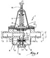
- a pressure reducing valve 1 comprises an inlet conduit 2 connected to an upstream network 3 and an outlet conduit 4 connected to a downstream network 5.
- the duct 2 comprises an outlet port 2 disposed at the interior of a chamber 6, so that the water emerging through the orifice 2 a is directed in a direction XX 'generally perpendicular to the axis of the networks 3 and 5.
- a movable element 7 is also arranged in the chamber 6 and movable in translation in direction XX ′ under the effect of the action of a cup 8 controlled by a spring 9 and of a membrane 10 subjected to the pressure P 0 prevailing in the chamber 6.
- the movable assembly 7 is provided with a rod 11 guided inside a plug 12 screwed onto the body 13 of the reducer 1.
- the equipment 7 comprises a valve holder 14 on which is mounted a valve 15 made of elastic material, such as as for example an elastomer, and capable of coming to bear against the edge 2 b of the orifice 2 a .
- the set pressure in the network 5 is adjusted by adjusting the force exerted by the spring 9 and the cup 8 on the membrane 10 by means of an adjusting screw 16.
- the pressure P 0 which is substantially equal to P ', exerts on the membrane 10 a vertical force directed upwards which tends to lift the moving element 7 and, therefore, to bring the valve 15 closer to the edge 2 b of the orifice 2 a , so that the flow section between the orifice 2 a and the valve 15 is reduced.
- This reduction in the flow section induces a reduction in the pressures P 0 and P '.
- the flow F of the water exiting the duct 2 through the opening 2a faces the upper surface 15 a of the valve 15 disposed facing the orifice 2a.
- the flow F is thus divided and is distributed in a generally circular manner by licking a peripheral surface 14 a of the valve holder 14 which surrounds the valve 15.
- a trellis structure 20 is provided and includes an annular zone 20 a disposed on the surface 14 a , so that the flow F flowing from the orifice 2 a licks the area 20 a of the structure 20.
- the speed of the flow F is thus substantially reduced by the structure 20, so that the flow velocity profile V has a shape close to the curve shown on the right of Figure 2 which is similar to a laminar flow profile.
- the decrease in speed V in the vicinity of the surface 14a and of the structure 20 results in an increase in the flow pressure in the vicinity of this surface, which has the effect of reducing the risks of cavitation.
- the structure 20 constitutes a means for stabilizing and slowing down the flow F in the vicinity of the surface 14 a .
- Practical tests have made it possible to demonstrate that, under the conditions of ISO 3822-3 and with an upstream pressure of around 8 bars and a downstream pressure of around 2.5 bars in flow, the noise difference compared to a reference sample is greater by 7 decibels for a pressure reducer equipped with the trellis structure 20 compared to the same reducer without such a structure.
- part 20 a of the structure 20 visible in FIG. 4 is arranged substantially parallel to the surface 14 a , so that it is permanently licked by the flow F flowing through the orifice 2 a , This has the effect that the impurities which could accumulate in the lattice structure are permanently evacuated, so that the latter effectively fulfills its role throughout the service life of the reducer.
- the structure 20 can be produced by weaving threads metallic or synthetic material or in a sheet of expanded metal.
- the meshes of structure 20 have dimensions of the order of 0.5 mm by 0.5 mm. We were able to demonstrate experimentally that meshes larger than 1 mm do not not allow the flow of flow F to be effectively slowed down. On the contrary, meshes smaller than 0.1 mm tend to clogging, impurities being only slightly entrained by the flow of flow F, because they are retained too important inside the structure 20.
- the structure 20 has a central zone 20 b intended to be wedged at the bottom of a housing 14 b for receiving the valve 15 in the valve holder of the moving element 14.
- the structure 20, which extends over the entire width of the valve 15, is firmly held in position relative to the movable element 7 by virtue of the installation of the valve 15.
- the valve 15 can also be fixed on the door valve 14 by a screw not shown.
- the structure 20 is shown conformed to the respective dimensions of the housing 14b and the valve 15. It is also possible to have a structure 20 in the form of a flat disc above the valve holder 14 and stamp that -ci during the establishment of the valve 15 inside the housing 14 b . A ring of lattice structure is obtained which then protrudes from the housing 14 b , this ring being able to be folded over the surface 14 a so as to form an annular zone 20 a intended to be licked by the flow F.
- a mobile assembly 107 comprises a valve holder 114 which carries a valve 115 intended to be moved opposite the outlet orifice 102 a of an intake duct 102, this orifice 102 a being provided with an edge 102 b .
- the upper surface 115 a of the valve 115 is oriented towards the edge 102 b of the orifice 102 a .
- a trellis structure 120 is arranged around the valve 115 in the vicinity of the peripheral surface 114 a of the valve holder 114 which surrounds the valve 115.
- the structure 120 is formed of strips 120 a which extend radially from the valve 115 and are arranged in the form of loops, so that it has two superposed layers 120 b and 120 c which are arranged substantially parallel to the surface 114 a .
- This multilayer structure could be transposed to embodiment of Figures 1 to 4.
- a housing 114 b is provided in the valve holder 114 of the movable element 107, said housing being accessible from the side of the valve holder 114 opposite the side 114 a.
- a plug 121 is adapted to be screwed into the valve carrier 114 so as to trap the valve 115 inside the housing 114 b.
- the valve 115 has an external flange 115 b intended to come into abutment against a shoulder 114 c of the housing 114 b .
- the strips 120 a of lattice structure are wedged between the valve 115 and the shoulder 114 c , so that it is not necessary to provide any particular fixing device for maintaining the strips 120 a in position.
- the flow F of water flowing through the orifice 102 a licks the strips 120 a , so that the tangential speed of the flow F at the level of the surface 114 a is greatly reduced, or even zero.
- a mobile assembly 207 comprises a holder valve 214 which carries a valve 215.
- a large number of son 220 are arranged radially from a housing for receiving the valve 215 in the valve holder 214, on the peripheral surface 214 of the valve holder which surrounds the valve 215.
- these threads have the function of stabilizing and slowing down the flow of the flow of liquid which licks the surface 214 a .
- the wires 220 can be obtained from a trellis structure of the type of the structure 20, this structure being wedged under the valve 215 in its receiving housing in the manner described with reference to the first embodiment.
- the part of the trellis structure which protrudes from the housing and rests on the surface 214 a can be dewoven by removing the non-radial wires.
- the wires 220 have a wavy shape, resulting from their previous weaving, which further improves the braking effect obtained on the flow during flow.
- These wires can be made of flexible material and shaped so that they are oriented upwards in the absence of flow, thus forming a barrier or an obstacle, while they can be folded down or laid down towards the surface 214 a under the effect of flow.
- a valve holder 314 making part of a moving part 307 is provided with a housing 314 b for receiving a valve 315.
- the surface 314 a of the valve holder 314 disposed around the valve 315 is provided with grooves 320 obtained by knurling. These grooves can also be produced by milling, stamping or knurling, or even by molding, these grooves extending in several directions on the surface 314 a . Like the previous devices, these grooves have the function of stabilizing and slowing down the flow of the flow emerging from an outlet orifice disposed opposite the valve 315.
- grooves 320 of this latter embodiment could be associated with lattice structures or son of the previous embodiments, which would allow to accumulate the benefits obtained.
- a valve holder 414 forming part a movable assembly 407 is provided with a housing 414 b for receiving a valve 415.
- the surface 414 a of the valve holder 414 disposed around the valve 415 is equipped with a structure 420 designed to be licked by the flow of water directed towards the valve 415.
- This structure 420 is formed of a band 420 a disposed flat, around the valve 415, on the surface 414 a and carrying wires or bristles 420 b oriented in a direction generally perpendicular to the strip 420 a or at surface 414 a . These wires or bristles 420 b thus constitute a local retarder for the flow of liquid in the vicinity of the surface 414 a .
- the structure 420 can in particular be formed of a plate provided with hooks or loops as known from the removable fastening systems with loops and hooks widely used in the fields of sports or leisure clothing.
- the strip 420 can also be made from a piece of fabric or molded from plastic.
- the wires or bristles 422 can be mounted by any appropriate means on the strip 420 a and in particular can be obtained by molding with the latter when the structure 420 is made completely of plastic.
- the band 420 a can be glued to the valve holder 414 or wedged under the valve 415 as in the embodiments of FIGS. 1 to 7. More generally, the band 420 a can be fixed to the valve holder 414 by any suitable means .
- the wires or bristles 420 b can be replaced by semi-rigid pins or rigid fingers extending in a direction generally perpendicular to the surface 414 a .
- the wires, bristles, pins or fingers have a height low enough for the liquid flow licks their ends without constituting a barrier or filter likely to clog.
- the invention has been shown with a reduction gear pressure. It is however applicable to other types of globe or globe valves, whether ordered manually or automatically, as long as they understand a mobile crew carrying a valve.
Landscapes
- Physics & Mathematics (AREA)
- Fluid Mechanics (AREA)
- General Physics & Mathematics (AREA)
- Engineering & Computer Science (AREA)
- Automation & Control Theory (AREA)
- Details Of Valves (AREA)
- Fluid-Pressure Circuits (AREA)
- Control Of Fluid Pressure (AREA)
- Valves And Accessory Devices For Braking Systems (AREA)
- Control Of Transmission Device (AREA)
- General Details Of Gearings (AREA)
- Supply Devices, Intensifiers, Converters, And Telemotors (AREA)
- Lift Valve (AREA)
Applications Claiming Priority (2)
| Application Number | Priority Date | Filing Date | Title |
|---|---|---|---|
| FR9801318 | 1998-01-30 | ||
| FR9801318A FR2774449B1 (fr) | 1998-01-30 | 1998-01-30 | Robinet a clapet ou a soupape, notamment reducteur de pression pour circuit hydraulique |
Publications (2)
| Publication Number | Publication Date |
|---|---|
| EP0933574A1 true EP0933574A1 (de) | 1999-08-04 |
| EP0933574B1 EP0933574B1 (de) | 2004-01-02 |
Family
ID=9522609
Family Applications (1)
| Application Number | Title | Priority Date | Filing Date |
|---|---|---|---|
| EP19990420024 Expired - Lifetime EP0933574B1 (de) | 1998-01-30 | 1999-01-28 | Druckminderer für Hydraulikanlagen |
Country Status (4)
| Country | Link |
|---|---|
| EP (1) | EP0933574B1 (de) |
| AT (1) | ATE257229T1 (de) |
| DE (1) | DE69913872T2 (de) |
| FR (1) | FR2774449B1 (de) |
Citations (7)
| Publication number | Priority date | Publication date | Assignee | Title |
|---|---|---|---|---|
| US2135670A (en) * | 1936-03-28 | 1938-11-08 | Sloan Valve Co | Valve |
| DE1067653B (de) * | 1955-05-28 | 1959-10-22 | Siemens Ag | Druckreduzierventil mit Einrichtung zur Verminderung von Geraeuschen und Vibrationen |
| DE1919731A1 (de) * | 1967-07-22 | 1970-11-05 | Hansa Metallwerke Ag | Vorrichtung zur Stroemungsberuhigung und Geraeuschdaempfung im Wasserfluss bei Niederschraub-Absperrventilen |
| DE2038051A1 (de) * | 1970-07-31 | 1972-02-10 | Hansa Metallwerke Ag | Druckreduzierventil,insbesondere fuer sanitaere Anlagen |
| DE2257196A1 (de) * | 1972-11-22 | 1974-06-06 | Vaillant Joh Kg | Ventil |
| EP0311573A1 (de) * | 1987-09-18 | 1989-04-12 | MAMOLI ROBINETTERIA S.p.A. | Kartusche für Mischhähne mit keramischer Verschlussplatte |
| EP0612005A1 (de) * | 1993-02-17 | 1994-08-24 | COMAP société anonyme | Fluiddruckminderer mit Kanüle und Sattel |
-
1998
- 1998-01-30 FR FR9801318A patent/FR2774449B1/fr not_active Expired - Fee Related
-
1999
- 1999-01-28 AT AT99420024T patent/ATE257229T1/de not_active IP Right Cessation
- 1999-01-28 EP EP19990420024 patent/EP0933574B1/de not_active Expired - Lifetime
- 1999-01-28 DE DE1999613872 patent/DE69913872T2/de not_active Expired - Lifetime
Patent Citations (7)
| Publication number | Priority date | Publication date | Assignee | Title |
|---|---|---|---|---|
| US2135670A (en) * | 1936-03-28 | 1938-11-08 | Sloan Valve Co | Valve |
| DE1067653B (de) * | 1955-05-28 | 1959-10-22 | Siemens Ag | Druckreduzierventil mit Einrichtung zur Verminderung von Geraeuschen und Vibrationen |
| DE1919731A1 (de) * | 1967-07-22 | 1970-11-05 | Hansa Metallwerke Ag | Vorrichtung zur Stroemungsberuhigung und Geraeuschdaempfung im Wasserfluss bei Niederschraub-Absperrventilen |
| DE2038051A1 (de) * | 1970-07-31 | 1972-02-10 | Hansa Metallwerke Ag | Druckreduzierventil,insbesondere fuer sanitaere Anlagen |
| DE2257196A1 (de) * | 1972-11-22 | 1974-06-06 | Vaillant Joh Kg | Ventil |
| EP0311573A1 (de) * | 1987-09-18 | 1989-04-12 | MAMOLI ROBINETTERIA S.p.A. | Kartusche für Mischhähne mit keramischer Verschlussplatte |
| EP0612005A1 (de) * | 1993-02-17 | 1994-08-24 | COMAP société anonyme | Fluiddruckminderer mit Kanüle und Sattel |
Also Published As
| Publication number | Publication date |
|---|---|
| EP0933574B1 (de) | 2004-01-02 |
| DE69913872T2 (de) | 2004-10-14 |
| DE69913872D1 (de) | 2004-02-05 |
| ATE257229T1 (de) | 2004-01-15 |
| FR2774449A1 (fr) | 1999-08-06 |
| FR2774449B1 (fr) | 2000-03-31 |
Similar Documents
| Publication | Publication Date | Title |
|---|---|---|
| EP0798012B1 (de) | Ventil zur Behandlung von Hydrocephalus | |
| FR2795800A1 (fr) | Appareil de prevention d'inversion d'ecoulement | |
| EP0258129A1 (de) | Thermostatische Mengenvorrichtungen, insbesondere für Wasserverteilung | |
| FR2714705A1 (fr) | Obturateur de trop-plein. | |
| FR2509343A1 (fr) | Regard de visite pour canalisations d'assainissement | |
| BE1013801A3 (fr) | Vanne a levee. | |
| CH670688A5 (de) | ||
| EP0933574B1 (de) | Druckminderer für Hydraulikanlagen | |
| FR2639084A1 (fr) | Robinetterie de valve de corps de chauffe | |
| WO2017186665A1 (fr) | Unité de mélange et robinet mitigeur comprenant une telle unité de mélange | |
| FR2665236A1 (fr) | Soupape de decharge de securite. | |
| FR2803011A1 (fr) | Dispositif de prevention de coups de belier | |
| FR2594206A1 (fr) | Dispositif d'amortissement phonique pour conduite d'installation sanitaire | |
| FR2620785A1 (fr) | Organe de controle de l'ecoulement d'un fluide constituant au moins un clapet anti-retour | |
| FR2828547A3 (fr) | Soupape de securite a double fonction | |
| FR2602024A1 (fr) | Mitigeur a usage sanitaire | |
| FR2555700A1 (fr) | Soupape de pression | |
| EP0118647A1 (de) | Hahn für Spülkasten | |
| CH616216A5 (en) | Cock for a flushing mechanism | |
| EP0424274B1 (de) | Vorrichtung zur Wasserzuführung, insbesondere für einen WC-Spülkasten | |
| FR2638503A1 (fr) | Vanne a disques a manchon de decharge amovible pour l'ecoulement d'un fluide | |
| FR2600394A1 (fr) | Soupape pour installations de chauffage de vehicules | |
| CA2314770A1 (fr) | Dispositif anti-retour | |
| FR2654178A1 (fr) | Soupape distributrice comportant une soupape de purge. | |
| FR2460002A1 (fr) | Regulateur de debit de liquide |
Legal Events
| Date | Code | Title | Description |
|---|---|---|---|
| PUAI | Public reference made under article 153(3) epc to a published international application that has entered the european phase |
Free format text: ORIGINAL CODE: 0009012 |
|
| AK | Designated contracting states |
Kind code of ref document: A1 Designated state(s): AT BE CH DE FI FR GB IE IT LI NL SE |
|
| AX | Request for extension of the european patent |
Free format text: AL;LT;LV;MK;RO;SI |
|
| 17P | Request for examination filed |
Effective date: 19991111 |
|
| AKX | Designation fees paid |
Free format text: AT BE CH DE FI FR GB IE IT LI NL SE |
|
| 17Q | First examination report despatched |
Effective date: 20021209 |
|
| GRAH | Despatch of communication of intention to grant a patent |
Free format text: ORIGINAL CODE: EPIDOS IGRA |
|
| RTI1 | Title (correction) |
Free format text: PRESSURE REDUCING VALVE FOR A HYDRAULIC CIRCUIT |
|
| GRAS | Grant fee paid |
Free format text: ORIGINAL CODE: EPIDOSNIGR3 |
|
| GRAA | (expected) grant |
Free format text: ORIGINAL CODE: 0009210 |
|
| AK | Designated contracting states |
Kind code of ref document: B1 Designated state(s): AT BE CH DE FI FR GB IE IT LI NL SE |
|
| PG25 | Lapsed in a contracting state [announced via postgrant information from national office to epo] |
Ref country code: NL Free format text: LAPSE BECAUSE OF FAILURE TO SUBMIT A TRANSLATION OF THE DESCRIPTION OR TO PAY THE FEE WITHIN THE PRESCRIBED TIME-LIMIT Effective date: 20040102 Ref country code: IT Free format text: LAPSE BECAUSE OF FAILURE TO SUBMIT A TRANSLATION OF THE DESCRIPTION OR TO PAY THE FEE WITHIN THE PRESCRIBED TIME-LIMIT;WARNING: LAPSES OF ITALIAN PATENTS WITH EFFECTIVE DATE BEFORE 2007 MAY HAVE OCCURRED AT ANY TIME BEFORE 2007. THE CORRECT EFFECTIVE DATE MAY BE DIFFERENT FROM THE ONE RECORDED. Effective date: 20040102 Ref country code: IE Free format text: LAPSE BECAUSE OF FAILURE TO SUBMIT A TRANSLATION OF THE DESCRIPTION OR TO PAY THE FEE WITHIN THE PRESCRIBED TIME-LIMIT Effective date: 20040102 Ref country code: GB Free format text: LAPSE BECAUSE OF FAILURE TO SUBMIT A TRANSLATION OF THE DESCRIPTION OR TO PAY THE FEE WITHIN THE PRESCRIBED TIME-LIMIT Effective date: 20040102 Ref country code: FI Free format text: LAPSE BECAUSE OF FAILURE TO SUBMIT A TRANSLATION OF THE DESCRIPTION OR TO PAY THE FEE WITHIN THE PRESCRIBED TIME-LIMIT Effective date: 20040102 Ref country code: AT Free format text: LAPSE BECAUSE OF FAILURE TO SUBMIT A TRANSLATION OF THE DESCRIPTION OR TO PAY THE FEE WITHIN THE PRESCRIBED TIME-LIMIT Effective date: 20040102 |
|
| REG | Reference to a national code |
Ref country code: GB Ref legal event code: FG4D Free format text: NOT ENGLISH |
|
| REG | Reference to a national code |
Ref country code: CH Ref legal event code: EP |
|
| REG | Reference to a national code |
Ref country code: IE Ref legal event code: FG4D Free format text: FRENCH |
|
| PG25 | Lapsed in a contracting state [announced via postgrant information from national office to epo] |
Ref country code: LI Free format text: LAPSE BECAUSE OF NON-PAYMENT OF DUE FEES Effective date: 20040131 Ref country code: CH Free format text: LAPSE BECAUSE OF NON-PAYMENT OF DUE FEES Effective date: 20040131 Ref country code: BE Free format text: LAPSE BECAUSE OF NON-PAYMENT OF DUE FEES Effective date: 20040131 |
|
| REF | Corresponds to: |
Ref document number: 69913872 Country of ref document: DE Date of ref document: 20040205 Kind code of ref document: P |
|
| PG25 | Lapsed in a contracting state [announced via postgrant information from national office to epo] |
Ref country code: SE Free format text: LAPSE BECAUSE OF FAILURE TO SUBMIT A TRANSLATION OF THE DESCRIPTION OR TO PAY THE FEE WITHIN THE PRESCRIBED TIME-LIMIT Effective date: 20040402 |
|
| NLV1 | Nl: lapsed or annulled due to failure to fulfill the requirements of art. 29p and 29m of the patents act | ||
| GBV | Gb: ep patent (uk) treated as always having been void in accordance with gb section 77(7)/1977 [no translation filed] |
Effective date: 20040102 |
|
| BERE | Be: lapsed |
Owner name: DESBORDES Effective date: 20040131 |
|
| REG | Reference to a national code |
Ref country code: IE Ref legal event code: FD4D |
|
| REG | Reference to a national code |
Ref country code: CH Ref legal event code: PL |
|
| PLBE | No opposition filed within time limit |
Free format text: ORIGINAL CODE: 0009261 |
|
| STAA | Information on the status of an ep patent application or granted ep patent |
Free format text: STATUS: NO OPPOSITION FILED WITHIN TIME LIMIT |
|
| 26N | No opposition filed |
Effective date: 20041005 |
|
| REG | Reference to a national code |
Ref country code: DE Ref legal event code: R082 Ref document number: 69913872 Country of ref document: DE Representative=s name: PFENNING MEINIG & PARTNER GBR, DE |
|
| PGFP | Annual fee paid to national office [announced via postgrant information from national office to epo] |
Ref country code: FR Payment date: 20131212 Year of fee payment: 16 |
|
| REG | Reference to a national code |
Ref country code: FR Ref legal event code: TP Owner name: SOCLA, FR Effective date: 20140210 |
|
| REG | Reference to a national code |
Ref country code: DE Ref legal event code: R082 Ref document number: 69913872 Country of ref document: DE Representative=s name: PFENNING MEINIG & PARTNER GBR, DE Effective date: 20140207 Ref country code: DE Ref legal event code: R081 Ref document number: 69913872 Country of ref document: DE Owner name: SOCLA, FR Free format text: FORMER OWNER: DESBORDES, VILLEURBANNE, FR Effective date: 20140207 Ref country code: DE Ref legal event code: R081 Ref document number: 69913872 Country of ref document: DE Owner name: SOCLA S.A.S, FR Free format text: FORMER OWNER: DESBORDES, VILLEURBANNE, FR Effective date: 20140207 |
|
| PGFP | Annual fee paid to national office [announced via postgrant information from national office to epo] |
Ref country code: DE Payment date: 20140107 Year of fee payment: 16 |
|
| REG | Reference to a national code |
Ref country code: DE Ref legal event code: R082 Ref document number: 69913872 Country of ref document: DE Representative=s name: PFENNING MEINIG & PARTNER GBR, DE Effective date: 20140528 Ref country code: DE Ref legal event code: R081 Ref document number: 69913872 Country of ref document: DE Owner name: SOCLA, FR Free format text: FORMER OWNER: SOCLA S.A.S, VIREY-LE-GRAND, FR Effective date: 20140528 |
|
| REG | Reference to a national code |
Ref country code: DE Ref legal event code: R119 Ref document number: 69913872 Country of ref document: DE |
|
| PG25 | Lapsed in a contracting state [announced via postgrant information from national office to epo] |
Ref country code: DE Free format text: LAPSE BECAUSE OF NON-PAYMENT OF DUE FEES Effective date: 20150801 |
|
| REG | Reference to a national code |
Ref country code: FR Ref legal event code: ST Effective date: 20150930 |
|
| PG25 | Lapsed in a contracting state [announced via postgrant information from national office to epo] |
Ref country code: FR Free format text: LAPSE BECAUSE OF NON-PAYMENT OF DUE FEES Effective date: 20150202 |