EP0933609B1 - Echangeur de chaleur - Google Patents
Echangeur de chaleur Download PDFInfo
- Publication number
- EP0933609B1 EP0933609B1 EP97944196A EP97944196A EP0933609B1 EP 0933609 B1 EP0933609 B1 EP 0933609B1 EP 97944196 A EP97944196 A EP 97944196A EP 97944196 A EP97944196 A EP 97944196A EP 0933609 B1 EP0933609 B1 EP 0933609B1
- Authority
- EP
- European Patent Office
- Prior art keywords
- temperature fluid
- heat
- low
- transfer plates
- passages
- Prior art date
- Legal status (The legal status is an assumption and is not a legal conclusion. Google has not performed a legal analysis and makes no representation as to the accuracy of the status listed.)
- Expired - Lifetime
Links
- 239000012530 fluid Substances 0.000 claims description 47
- 230000002093 peripheral effect Effects 0.000 claims description 12
- 239000000567 combustion gas Substances 0.000 description 35
- 238000005219 brazing Methods 0.000 description 10
- 238000007599 discharging Methods 0.000 description 7
- 239000000463 material Substances 0.000 description 6
- 238000005520 cutting process Methods 0.000 description 4
- 239000007789 gas Substances 0.000 description 4
- 238000003825 pressing Methods 0.000 description 3
- 239000002184 metal Substances 0.000 description 2
- 238000005192 partition Methods 0.000 description 2
- 238000011144 upstream manufacturing Methods 0.000 description 2
- 230000015556 catabolic process Effects 0.000 description 1
- 230000003247 decreasing effect Effects 0.000 description 1
- 238000006731 degradation reaction Methods 0.000 description 1
- 230000002708 enhancing effect Effects 0.000 description 1
- 238000004519 manufacturing process Methods 0.000 description 1
- 229910001220 stainless steel Inorganic materials 0.000 description 1
- 239000010935 stainless steel Substances 0.000 description 1
Images


Classifications
-
- F—MECHANICAL ENGINEERING; LIGHTING; HEATING; WEAPONS; BLASTING
- F28—HEAT EXCHANGE IN GENERAL
- F28D—HEAT-EXCHANGE APPARATUS, NOT PROVIDED FOR IN ANOTHER SUBCLASS, IN WHICH THE HEAT-EXCHANGE MEDIA DO NOT COME INTO DIRECT CONTACT
- F28D9/00—Heat-exchange apparatus having stationary plate-like or laminated conduit assemblies for both heat-exchange media, the media being in contact with different sides of a conduit wall
-
- F—MECHANICAL ENGINEERING; LIGHTING; HEATING; WEAPONS; BLASTING
- F28—HEAT EXCHANGE IN GENERAL
- F28F—DETAILS OF HEAT-EXCHANGE AND HEAT-TRANSFER APPARATUS, OF GENERAL APPLICATION
- F28F13/00—Arrangements for modifying heat-transfer, e.g. increasing, decreasing
- F28F13/06—Arrangements for modifying heat-transfer, e.g. increasing, decreasing by affecting the pattern of flow of the heat-exchange media
- F28F13/08—Arrangements for modifying heat-transfer, e.g. increasing, decreasing by affecting the pattern of flow of the heat-exchange media by varying the cross-section of the flow channels
-
- F—MECHANICAL ENGINEERING; LIGHTING; HEATING; WEAPONS; BLASTING
- F28—HEAT EXCHANGE IN GENERAL
- F28D—HEAT-EXCHANGE APPARATUS, NOT PROVIDED FOR IN ANOTHER SUBCLASS, IN WHICH THE HEAT-EXCHANGE MEDIA DO NOT COME INTO DIRECT CONTACT
- F28D9/00—Heat-exchange apparatus having stationary plate-like or laminated conduit assemblies for both heat-exchange media, the media being in contact with different sides of a conduit wall
- F28D9/0012—Heat-exchange apparatus having stationary plate-like or laminated conduit assemblies for both heat-exchange media, the media being in contact with different sides of a conduit wall the apparatus having an annular form
- F28D9/0018—Heat-exchange apparatus having stationary plate-like or laminated conduit assemblies for both heat-exchange media, the media being in contact with different sides of a conduit wall the apparatus having an annular form without any annular circulation of the heat exchange media
-
- F—MECHANICAL ENGINEERING; LIGHTING; HEATING; WEAPONS; BLASTING
- F28—HEAT EXCHANGE IN GENERAL
- F28D—HEAT-EXCHANGE APPARATUS, NOT PROVIDED FOR IN ANOTHER SUBCLASS, IN WHICH THE HEAT-EXCHANGE MEDIA DO NOT COME INTO DIRECT CONTACT
- F28D9/00—Heat-exchange apparatus having stationary plate-like or laminated conduit assemblies for both heat-exchange media, the media being in contact with different sides of a conduit wall
- F28D9/0025—Heat-exchange apparatus having stationary plate-like or laminated conduit assemblies for both heat-exchange media, the media being in contact with different sides of a conduit wall the conduits being formed by zig-zag bend plates
Definitions
- the present invention relates to an annular-shaped heat exchanger including high-temperature fluid passages and low-temperature fluid passages defined alternately by folding a plurality of first heat-transfer plates and a plurality of second heat-transfer plates in a zigzag fashion comprising the features of the preamble of claim 1.
- Such a heat exchanger is known from Japanese Patent Application Laid-open No.57-2983.
- Japanese Patent Application Laid-open No.59-183296 which includes high-temperature fluid passages and low-temperature fluid passages defined alternately between heat-transfer plates disposed in parallel, and outlets and inlets for a high-temperature fluid and low-temperature fluid, which are defined by cutting opposite ends of each of the heat-transfer plates into angle shapes.
- the present invention has been accomplished with the above circumstances in view, and it is an object of the present invention to provide a heat exchanger in which a good material yield is provided and moreover, it is easy to carry out the brazing of a member for forming a fluid duct.
- the radially outer peripheral walls are brazed to the plurality of first folding lines located on the radially outer side and the radially inner peripheral walls are brazed to the plurality of second folding lines located on the radially inner side in order to define the high-temperature fluid ducts connected to the high-temperature fluid passages and the low-temperature fluid ducts connected to the low-temperature fluid passages. Therefore, it is unnecessary to carry out a special working treatment in order to form brazed portions on the first and second heat-transfer plates, leading not only to a reduced number of working steps, but also to an increased brazing strength, as compared with the case where the first and second heat-transfer plates are brazed to the cut end surfaces.
- the high-temperature fluid passage inlet and the high-temperature fluid passage outlet are defined in the openings at the axially opposite ends of the high-temperature fluid passages, and the projection stripes provided on the first and second heat-transfer plates are brazed to one another to close the axially opposite ends of the low-temperature fluid passages, while defining the low-temperature fluid passage inlet in one of the radially outer and inner peripheral walls on the side of the high-temperature fluid passage outlet, and the low-temperature fluid passage outlet on the other of the radially outer and inner peripheral walls on the side of the high-temperature fluid passage inlet.
- the outlets and inlets for a high-temperature fluid and a low-temperature fluid can be defined.
- the projection stripes are used for closing the opposite ends of the low-temperature fluid passages and hence, it is unnecessary to provide flaps in a projecting manner on the first and second heat-transfer plates in place of the projection stripes, whereby the material yield can be further enhanced.
- Figs.1 to 9 show one embodiment of the present invention, wherein
- a gas turbine engine E includes an engine body 1 in which a combustor, a compressor, a turbine and the like (which are not shown) are accommodated.
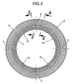
- An annular-shaped heat exchanger 2 is disposed to surround an outer periphery of the engine body 1.
- the heat exchanger 2 comprises four modules 2 1 having a center angle of 90° and arranged in a circumferential direction with bond surfaces 3 interposed therebetween.
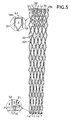
- Combustion gas passages 4 and air passages 5 are circumferentially alternately provided in the heat exchanger 2 (see Fig.5), so that a combustion gas of a relative high temperature passed through turbine is passed through the combustion gas passages 4, and air of a relative low temperature compressed in the compressor is passed through the air passages 5.
- a section in Fig.1 corresponds to the combustion gas passages 4, and the air passages 5 are defined adjacent this side and the other side of the combustion gas passages 4.
- the sectional shape of the heat exchanger 2 taken along its axis is an axially longer and radially shorter quadrilateral shape.
- a radially outer peripheral surface of the heat exchanger 2 is closed by a large-diameter cylindrical outer casing 6, and a radially inner peripheral surface of the heat exchanger 2 is closed by a small-diameter cylindrical inner casing 7.
- a front outer duct member 8o and a front inner duct member 8i are provided in a front portion of the heat exchanger 2, so that they are connected to front ends of the outer and inner casings 6 and 7, respectively.
- a rear outer duct member 10o and a rear inner duct member 10i are provided in a rear portion of the heat exchanger 2, so that they are connected to rear ends of the outer and inner casings 6 and 7, respectively.
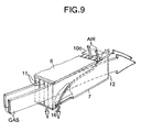
- Each of the combustion gas passages 4 in the heat exchanger 2 includes a combustion gas passage inlet 11 and a combustion gas passage outlet 12 at left and right portions of Fig.1.
- a combustion gas introducing space (referred to as a combustion gas introducing duct) 13 defined between the front outer duct member 8o and the front inner duct member 8i is connected at its downstream end to the combustion gas passage inlet 11, and a combustion gas discharging space (referred to as a combustion gas discharging duct) 14 defined between the rear outer duct member 10o and the rear inner duct member 10i is connected at its upstream end to the combustion gas passage outlet 12.
- Each of the air passages 5 in the heat exchanger 2 includes an air passage inlet 15 and an air passage outlet 16 at the right and upper portion and the left and lower portion of Fig.1, respectively.
- An air introducing space (referred to as an air introducing duct) 17 defined along an inner periphery of a rear outer housing 9 is connected at its downstream end to the air passage inlet 15.
- An air discharging space (referred to as an air discharging duct) 18 extending within the engine body 1 is connected at its upstream end to the air passage outlet 16.
- the temperature of the combustion gas which has driven the turbine is about 600 to 700°C in the combustion gas passage inlets 11.
- the combustion gas is cooled down to about 300 to 400°C in the combustion gas passage outlets 12 by conducting a heat-exchange between the combustion gas and the air when the combustion gas passes through the combustion gas passages 4.
- the temperature of the air compressed by the compressor is about 200 to 300°C in the air passage inlets 15.
- the air is heated up to about 500 to 600°C in the air passage outlets 16 by conducting a heat-exchange between the air and the combustion gas, which occurs when the air passes through the air passages 5.
- each of the modules 2 1 of the heat exchanger 2 is made from a folding plate blank 21 (see Fig. 7) produced by previously cutting a thin metal plate such as a stainless steel into a predetermined shape and then forming an irregularity on a surface of the cut plate by pressing.
- the folding plate blank 21 is comprised of first heat-transfer plates S1 and second heat-transfer plates S2 disposed alternately, and is folded into a zigzag fashion along crest-folding lines L 1 and valley-folding lines L 2 .
- crest-folding means folding into a convex toward this side or a closer side from the drawing sheet surface
- valley-folding means folding into a convex toward the other side or a far side from the drawing sheet surface.
- Each of the crest-folding lines L 1 and the valley-folding lines L 2 is not a simple straight line, but actually comprises an arcuate folding line or two parallel and adjacent folding lines for the purpose of forming a predetermined space between each of the first heat-transfer plates S1 and each of the second heat-transfer plates S2.
- the first projections 22 indicated by a mark X in Fig.7 protrude toward this side on the drawing sheet surface of Fig.7
- the second projections 23 indicated by a mark O in Fig.7 protrude toward the other side on the drawing sheet surface of Fig.7.
- the first and second projections 22 and 23 are arranged alternately (i.e., so that the first projections 22 are not continuous to one another and the second projections 23 are not continuous to one another).
- Front projection stripes 24 F and rear projection stripes 24 R which protrude toward this side on the drawing sheet surface of Fig. 7, are formed on front and rear ends of each of the first and second heat-transfer plates S1 and S2 by pressing.
- the first projections 22, the second projections 23, the front projection stripes 24 F and the rear projection stripes 24 R of the first heat-transfer plate S1 shown in Fig.3 are in an opposite recess-projection relationship with respect to that in the first heat-transfer plate S1 shown in Fig. 7. This is because Fig.3 shows a state in which the first heat-transfer plate S1 is viewed from the back side.
- the rear end of the outer casing 6 and a front end of the rear outer duct member 10o to which the crest-folding lines L 1 have been brazed are opposed to each other at a predetermined gap left therebetween, and the air passage inlet 15 is defined in this gap.
- the air passage outlet 16 formed into a small bore shape is defined to extend through front portions of the valley-folding lines L 2 and a front portion of the inner casing 7.
- air flowing in the air introducing duct 17 is guided through the air passage inlet 15 to the air passages 5 between the first and second heat-transfer plates S1 and S2, and discharged therefrom through the small bore-shaped air passage outlet 16 defined in the valley-folding lines L 2 and the inner casing 7 to the air discharging duct 18.
- Each of the first and second projections 22 and 23 has a substantially truncated conical shape, and the tip ends of the first and second projections 22 and 23 are in surface contact with each other to enhance the brazing strength.
- Each of the front and rear projection stripes 24 F and 24 R has also a substantially trapezoidal section, and the tip ends of the front and rear projection stripes 24 F and 24 R are also in surface contact with each other to enhance the brazing strength.
- the adjacent crest-folding lines L 1 cannot be brought into direct contact with each other, but the distance between the crest-folding lines L 1 is maintained constant by the contact of the first projections 22 to each other.
- the adjacent valley-folding lines L 2 cannot be brought into direct contact with each other, but the distance between the valley-folding lines L 2 is maintained constant by the contact of the second projections 23 to each other.
- the first and second heat-transfer plates S1 and S2 are disposed radiately from the center of the heat exchanger 2. Therefore, the distance between the adjacent first and second heat-transfer plates S1 and S2 assumes the maximum in the radially outer peripheral portion which is in contact with the outer casing 6, and the minimum in the radially inner peripheral portion which is in contact with the inner casing 7.
- the heights of the first projections 22, the second projections 23, the front projection stripes 24 F and the rear projection stripes 24 R are gradually increased outwards from the radially inner side, whereby the first and second heat-transfer plates S1 and S2 can be disposed exactly radiately (see Fig.5).
- the outer casing 6 and the inner casing 7 can be positioned concentrically, and the axial symmetry of the heat exchanger 2 can be maintained accurately.
- first and second heat-transfer plates S1 and S2 are of the same rectangular shape and hence, the folding plate blank 21 is also of a simple band shape, leading to the enhanced material yield, as compared with the case where ends of the first and second heat-transfer plates S1 and S2 are cut into an angle shape.
- the front projection stripes 24 F and the rear projection stripes 24 R are employed for closing the air passages 5 and hence, there is not a degradation in the material yield produced when flaps for closing the air passages 5 are projectingly provided at ends of the rectangular first and second heat-transfer plates S1 and S2.
- the front outer duct member 8o, the front inner duct member 8i, the rear outer duct member 10o and the rear inner duct member 10i for defining the high-temperature fluid introducing duct 13, the high-temperature fluid discharging duct 14, the low-temperature fluid introducing duct 17 and the low-temperature fluid discharging duct 18 are brazed to the crest-folding lines L 1 and the valley-folding lines L 2 of the first and second heat-transfer plates S1 and S2.
- the heat exchanger 2 By forming the heat exchanger 2 by a combination of the four modules 2 1 having the same structure, the manufacture of the heat exchanger can be facilitated, and the structure of the heat exchanger can be simplified.
- the folding plate blank 21 radiately and in the zigzag fashion to continuously form the first and second heat-transfer plates S1 and S2, the number of parts and the number of brazing points can remarkably be decreased, and moreover, the dimensional accuracy of a completed article can be enhanced, as compared with a case where a large number of first heat-transfer plates S1 independent from one another and a large number of second heat-transfer plates S2 independent from one another are brazed alternately.
- the pressure in the combustion gas passages 4 is relatively low, and the pressure in the air passages 5 is relatively high. For this reason, a flexural load is applied to the first and second heat-transfer plates S1 and S2 due to a difference between the pressures, but a sufficient rigidity capable of withstanding such load can be obtained by virtue of the first and second projections 22 and 23 which have been brought into abutment against each other and brazed with each other.
- the surface areas of the first and second heat-transfer plates S1 and S2 are increased by virtue of the first and second projections 22 and 23.
- the flows of the combustion gas and the air are agitated and hence, the heat exchange efficiency can be enhanced.
- heat exchanger 2 for the gas turbine engine E has been illustrated in the embodiment, but the present invention can be applied to heat exchangers for other applications.
Landscapes
- Engineering & Computer Science (AREA)
- Physics & Mathematics (AREA)
- Thermal Sciences (AREA)
- Mechanical Engineering (AREA)
- General Engineering & Computer Science (AREA)
- Heat-Exchange Devices With Radiators And Conduit Assemblies (AREA)
Claims (1)
- Echangeur de chaleur :caractérisé par des bandes en saillie (24F et 24R) disposées de chaque côté de chacune desdites premières et secondes plaques de transfert de chaleur (S1 et S2) et sur les extrémités avant et arrière de celles-ci et qui sont brasées les unes avec les autres, ce qui ferme les extrémités opposées axialement desdits passages de fluide à basse température (5).formé à partir d'une ébauche de plaque repliable (21) comprenant une pluralité de premières plaques quadrilatères de transfert de chaleur (S1) et une pluralité de secondes plaques quadrilatères de transfert de chaleur (S2) qui sont connectées ensemble de manière alternée par l'intermédiaire de premières et de secondes lignes de pliage (L1 et L2), ladite ébauche de plaque repliable (21) étant pliée en zigzag le long desdites premières et secondes lignes de pliage (L1 et L2), définissant ainsi des passages de fluide à haute température et à basse température qui s'étendent axialement (4 et 5) de manière alternée dans le sens de la circonférence ;des parois périphériques externes radiales (6, 8o et 10o) sont brasées sur ladite pluralité de premières lignes de pliage (L1) situées sur un côté radialement externe et des parois périphériques internes radiales (7, 8i et 10i) sont brasées sur ladite pluralité de secondes lignes de pliage (L2) situées sur un côté radialement interne, fermant ainsi radialement les périphéries interne et externe desdits passages de fluide à haute température et à basse température qui s'étendent axialement (4 et 5), tout en définissant des conduits pour fluide à haute température (13 et 14) connectés aux dits passages de fluide à haute température (4) et des conduits pour fluide à basse température (17 et 18) connectés aux dits passages de fluide à basse température (5) ;une admission de passage de fluide à haute température (11) et une sortie de passage de fluide à haute température (12) sont formées dans une ouverture à des extrémités axialement opposées desdits passages de fluide à haute température (4) ;une admission de passage de fluide à basse température (15) est formée dans l'une desdites parois périphériques externe et interne radiales (6, 8o et 10o ; 7, 8i et 10i) du côté de ladite sortie de passage de fluide à haute température (12), et une sortie de passage de fluide à basse température (16) est formée sur l'autre desdites parois périphériques externe et interne radiales (6, 8o et 10o ; 7, 8i et 10i) du côté de l'admission du passage de fluide à haute température (11), et des moyens destinés à fermer axialement les extrémités opposées desdits passages de fluide à basse température (5),
Applications Claiming Priority (3)
| Application Number | Priority Date | Filing Date | Title |
|---|---|---|---|
| JP27505896 | 1996-10-17 | ||
| JP27505896A JP3685890B2 (ja) | 1996-10-17 | 1996-10-17 | 熱交換器 |
| PCT/JP1997/003848 WO1998016790A1 (fr) | 1996-10-17 | 1997-10-17 | Echangeur de chaleur |
Publications (3)
| Publication Number | Publication Date |
|---|---|
| EP0933609A1 EP0933609A1 (fr) | 1999-08-04 |
| EP0933609A4 EP0933609A4 (fr) | 1999-12-15 |
| EP0933609B1 true EP0933609B1 (fr) | 2002-11-27 |
Family
ID=17550268
Family Applications (1)
| Application Number | Title | Priority Date | Filing Date |
|---|---|---|---|
| EP97944196A Expired - Lifetime EP0933609B1 (fr) | 1996-10-17 | 1997-10-17 | Echangeur de chaleur |
Country Status (9)
| Country | Link |
|---|---|
| US (1) | US6216774B1 (fr) |
| EP (1) | EP0933609B1 (fr) |
| JP (1) | JP3685890B2 (fr) |
| KR (1) | KR100328275B1 (fr) |
| CN (1) | CN1109876C (fr) |
| BR (1) | BR9712412A (fr) |
| CA (1) | CA2268889C (fr) |
| DE (1) | DE69717482T2 (fr) |
| WO (1) | WO1998016790A1 (fr) |
Families Citing this family (14)
| Publication number | Priority date | Publication date | Assignee | Title |
|---|---|---|---|---|
| US6951110B2 (en) * | 2000-11-06 | 2005-10-04 | Capstone Turbine Corporation | Annular recuperator design |
| JP4523149B2 (ja) * | 2000-12-25 | 2010-08-11 | 本田技研工業株式会社 | 熱交換器 |
| EP1347260B1 (fr) * | 2000-12-25 | 2009-06-10 | Honda Giken Kogyo Kabushiki Kaisha | Echangeur thermique |
| JP4523148B2 (ja) * | 2000-12-25 | 2010-08-11 | 本田技研工業株式会社 | 熱交換器 |
| US20020079085A1 (en) * | 2000-12-27 | 2002-06-27 | Rentz Lawrence Edward | Turbine recuperator |
| JP4732609B2 (ja) * | 2001-04-11 | 2011-07-27 | 株式会社ティラド | 熱交換器コア |
| US20020166657A1 (en) * | 2001-05-10 | 2002-11-14 | Marconi Communications, Inc. | Plastic heat exchanger and core thereof |
| JP2003021489A (ja) * | 2001-07-06 | 2003-01-24 | Toyo Radiator Co Ltd | 熱交換器の接合構造 |
| ATE524700T1 (de) * | 2005-07-19 | 2011-09-15 | Behr Gmbh & Co Kg | Wärmeübertrager |
| GB0809566D0 (en) * | 2008-05-27 | 2008-07-02 | Fortismanis Talivaldis | Heat exchanger design using corrugated metal sheets |
| EP2837905B1 (fr) * | 2013-08-12 | 2020-02-12 | Alfa Laval Corporate AB | Plaque de transfer de chaleur, échangeur de chaleur et procédé d'exploitation |
| HRP20201062T1 (hr) * | 2014-12-18 | 2020-10-30 | Zehnder Group International Ag | Izmjenjivač topline i uređaj za ventilaciju s njime |
| US10151497B2 (en) * | 2015-02-23 | 2018-12-11 | Seeley International Pty Ltd | Method of producing a micro-core heat exchanger for a compact indirect evaporative cooler |
| KR101717094B1 (ko) * | 2015-07-23 | 2017-03-27 | 주식회사 경동나비엔 | 열교환기 |
Family Cites Families (21)
| Publication number | Priority date | Publication date | Assignee | Title |
|---|---|---|---|---|
| US326839A (en) * | 1885-09-22 | braithwaite | ||
| US1941365A (en) * | 1931-09-22 | 1933-12-26 | Int Comb Eng Corp | Art of heat transfer |
| US2367223A (en) * | 1942-04-07 | 1945-01-16 | Gen Electric | Combined centrifugal compressor and cooler |
| DE1601216B2 (de) * | 1967-11-03 | 1971-06-16 | Linde Ag, 6200 Wiesbaden | Blechtafel fuer platten waermetauscher mit einem stapel solcher blechtafeln |
| US3513907A (en) * | 1968-04-17 | 1970-05-26 | United Aircraft Prod | Plural mode heat exchange apparatus |
| US3584682A (en) * | 1968-07-29 | 1971-06-15 | Borg Warner | Tubular heat transfer device |
| US3847211A (en) * | 1969-01-28 | 1974-11-12 | Sub Marine Syst Inc | Property interchange system for fluids |
| DE2408462A1 (de) * | 1974-02-22 | 1975-08-28 | Kernforschungsanlage Juelich | Waermetauscher fuer getrennt gefuehrte medien |
| US4131159A (en) * | 1976-07-26 | 1978-12-26 | Karen L. Beckmann | Heat exchanger |
| US4384611A (en) * | 1978-05-15 | 1983-05-24 | Hxk Inc. | Heat exchanger |
| US4314607A (en) * | 1979-11-14 | 1982-02-09 | Deschamps Laboratories, Inc. | Plate type heat exchanger |
| US4343355A (en) * | 1980-01-14 | 1982-08-10 | Caterpillar Tractor Co. | Low stress heat exchanger and method of making the same |
| JPS572983A (en) | 1980-06-09 | 1982-01-08 | Toshiba Corp | Opposed flow type heat exchanger |
| EP0055711B1 (fr) * | 1980-07-07 | 1985-10-09 | Caterpillar Tractor Co. | Echangeur de chaleur a profil bas et son procede de fabrication |
| US4475589A (en) * | 1981-01-21 | 1984-10-09 | Tokyo Shibaura Denki Kabushiki Kaisha | Heat exchanger device |
| DE3131091A1 (de) * | 1981-08-06 | 1983-02-24 | Klöckner-Humboldt-Deutz AG, 5000 Köln | Ringfoermiger rekuperativer waermetauscher |
| JPS59183296A (ja) | 1983-04-01 | 1984-10-18 | Yasuo Mori | プレ−トフイン型熱交換器 |
| GB9027994D0 (en) | 1990-12-22 | 1991-02-13 | Atomic Energy Authority Uk | Heat exchanger |
| US5340664A (en) * | 1993-09-29 | 1994-08-23 | Ceramatec, Inc. | Thermally integrated heat exchange system for solid oxide electrolyte systems |
| JPH08178578A (ja) | 1994-12-26 | 1996-07-12 | Daikin Ind Ltd | 熱交換エレメント及びその製造方法 |
| JP3030689B2 (ja) | 1995-09-08 | 2000-04-10 | 本田技研工業株式会社 | ガスタービンエンジン |
-
1996
- 1996-10-17 JP JP27505896A patent/JP3685890B2/ja not_active Expired - Fee Related
-
1997
- 1997-10-17 WO PCT/JP1997/003848 patent/WO1998016790A1/fr not_active Ceased
- 1997-10-17 BR BR9712412-5A patent/BR9712412A/pt not_active IP Right Cessation
- 1997-10-17 CA CA002268889A patent/CA2268889C/fr not_active Expired - Fee Related
- 1997-10-17 US US09/269,742 patent/US6216774B1/en not_active Expired - Fee Related
- 1997-10-17 KR KR1019997003243A patent/KR100328275B1/ko not_active Expired - Fee Related
- 1997-10-17 EP EP97944196A patent/EP0933609B1/fr not_active Expired - Lifetime
- 1997-10-17 DE DE69717482T patent/DE69717482T2/de not_active Expired - Fee Related
- 1997-10-17 CN CN97198928A patent/CN1109876C/zh not_active Expired - Fee Related
Also Published As
| Publication number | Publication date |
|---|---|
| US6216774B1 (en) | 2001-04-17 |
| WO1998016790A1 (fr) | 1998-04-23 |
| CA2268889A1 (fr) | 1998-04-23 |
| BR9712412A (pt) | 1999-10-19 |
| KR100328275B1 (ko) | 2002-03-16 |
| DE69717482T2 (de) | 2003-04-10 |
| JP3685890B2 (ja) | 2005-08-24 |
| CA2268889C (fr) | 2003-04-15 |
| DE69717482D1 (de) | 2003-01-09 |
| EP0933609A4 (fr) | 1999-12-15 |
| CN1234109A (zh) | 1999-11-03 |
| KR20000049152A (ko) | 2000-07-25 |
| JPH10122769A (ja) | 1998-05-15 |
| EP0933609A1 (fr) | 1999-08-04 |
| CN1109876C (zh) | 2003-05-28 |
Similar Documents
| Publication | Publication Date | Title |
|---|---|---|
| EP1022533B1 (fr) | Echangeur thermique | |
| EP0933608B1 (fr) | Echangeur de chaleur | |
| EP0933609B1 (fr) | Echangeur de chaleur | |
| EP0866299B1 (fr) | Echangeur de chaleur | |
| EP0955512B1 (fr) | Echangeur thermique | |
| CA2268706C (fr) | Echangeur de chaleur | |
| EP0977001B1 (fr) | Echangeur de chaleur | |
| JP3685888B2 (ja) | 熱交換器 | |
| JPH10122764A (ja) | 熱交換器 | |
| JP3689204B2 (ja) | 熱交換器 | |
| JP3685889B2 (ja) | 熱交換器 | |
| JP3715044B2 (ja) | 熱交換器 | |
| JPH10206048A (ja) | 熱交換器 | |
| JPH0942867A (ja) | 熱交換器 | |
| JPH10206043A (ja) | 熱交換器 | |
| JPH10122766A (ja) | 熱交換器 | |
| JPH0942868A (ja) | 熱交換器 |
Legal Events
| Date | Code | Title | Description |
|---|---|---|---|
| PUAI | Public reference made under article 153(3) epc to a published international application that has entered the european phase |
Free format text: ORIGINAL CODE: 0009012 |
|
| 17P | Request for examination filed |
Effective date: 19990415 |
|
| AK | Designated contracting states |
Kind code of ref document: A1 Designated state(s): DE FR GB |
|
| A4 | Supplementary search report drawn up and despatched |
Effective date: 19991103 |
|
| AK | Designated contracting states |
Kind code of ref document: A4 Designated state(s): DE FR GB |
|
| 17Q | First examination report despatched |
Effective date: 20010202 |
|
| GRAG | Despatch of communication of intention to grant |
Free format text: ORIGINAL CODE: EPIDOS AGRA |
|
| GRAG | Despatch of communication of intention to grant |
Free format text: ORIGINAL CODE: EPIDOS AGRA |
|
| GRAH | Despatch of communication of intention to grant a patent |
Free format text: ORIGINAL CODE: EPIDOS IGRA |
|
| GRAH | Despatch of communication of intention to grant a patent |
Free format text: ORIGINAL CODE: EPIDOS IGRA |
|
| GRAA | (expected) grant |
Free format text: ORIGINAL CODE: 0009210 |
|
| AK | Designated contracting states |
Kind code of ref document: B1 Designated state(s): DE FR GB |
|
| REG | Reference to a national code |
Ref country code: GB Ref legal event code: FG4D |
|
| REF | Corresponds to: |
Ref document number: 69717482 Country of ref document: DE Date of ref document: 20030109 |
|
| ET | Fr: translation filed | ||
| PLBE | No opposition filed within time limit |
Free format text: ORIGINAL CODE: 0009261 |
|
| STAA | Information on the status of an ep patent application or granted ep patent |
Free format text: STATUS: NO OPPOSITION FILED WITHIN TIME LIMIT |
|
| 26N | No opposition filed |
Effective date: 20030828 |
|
| PGFP | Annual fee paid to national office [announced via postgrant information from national office to epo] |
Ref country code: FR Payment date: 20051010 Year of fee payment: 9 |
|
| PGFP | Annual fee paid to national office [announced via postgrant information from national office to epo] |
Ref country code: GB Payment date: 20051012 Year of fee payment: 9 |
|
| PGFP | Annual fee paid to national office [announced via postgrant information from national office to epo] |
Ref country code: DE Payment date: 20051014 Year of fee payment: 9 |
|
| PG25 | Lapsed in a contracting state [announced via postgrant information from national office to epo] |
Ref country code: DE Free format text: LAPSE BECAUSE OF NON-PAYMENT OF DUE FEES Effective date: 20070501 |
|
| GBPC | Gb: european patent ceased through non-payment of renewal fee |
Effective date: 20061017 |
|
| REG | Reference to a national code |
Ref country code: FR Ref legal event code: ST Effective date: 20070629 |
|
| PG25 | Lapsed in a contracting state [announced via postgrant information from national office to epo] |
Ref country code: GB Free format text: LAPSE BECAUSE OF NON-PAYMENT OF DUE FEES Effective date: 20061017 |
|
| PG25 | Lapsed in a contracting state [announced via postgrant information from national office to epo] |
Ref country code: FR Free format text: LAPSE BECAUSE OF NON-PAYMENT OF DUE FEES Effective date: 20061031 |