EP0933661A2 - Dispositif pour fixer et positionner un bout de fibre optique et utilisation - Google Patents
Dispositif pour fixer et positionner un bout de fibre optique et utilisation Download PDFInfo
- Publication number
- EP0933661A2 EP0933661A2 EP99108311A EP99108311A EP0933661A2 EP 0933661 A2 EP0933661 A2 EP 0933661A2 EP 99108311 A EP99108311 A EP 99108311A EP 99108311 A EP99108311 A EP 99108311A EP 0933661 A2 EP0933661 A2 EP 0933661A2
- Authority
- EP
- European Patent Office
- Prior art keywords
- housing
- optical fiber
- ball lens
- cylindrical body
- sleeve
- Prior art date
- Legal status (The legal status is an assumption and is not a legal conclusion. Google has not performed a legal analysis and makes no representation as to the accuracy of the status listed.)
- Withdrawn
Links
Images

Classifications
-
- G—PHYSICS
- G02—OPTICS
- G02B—OPTICAL ELEMENTS, SYSTEMS OR APPARATUS
- G02B6/00—Light guides; Structural details of arrangements comprising light guides and other optical elements, e.g. couplings
- G02B6/24—Coupling light guides
- G02B6/42—Coupling light guides with opto-electronic elements
- G02B6/4292—Coupling light guides with opto-electronic elements the light guide being disconnectable from the opto-electronic element, e.g. mutually self aligning arrangements
-
- G—PHYSICS
- G02—OPTICS
- G02B—OPTICAL ELEMENTS, SYSTEMS OR APPARATUS
- G02B6/00—Light guides; Structural details of arrangements comprising light guides and other optical elements, e.g. couplings
- G02B6/24—Coupling light guides
- G02B6/42—Coupling light guides with opto-electronic elements
- G02B6/4201—Packages, e.g. shape, construction, internal or external details
- G02B6/4204—Packages, e.g. shape, construction, internal or external details the coupling comprising intermediate optical elements, e.g. lenses, holograms
- G02B6/4207—Packages, e.g. shape, construction, internal or external details the coupling comprising intermediate optical elements, e.g. lenses, holograms with optical elements reducing the sensitivity to optical feedback
-
- G—PHYSICS
- G02—OPTICS
- G02B—OPTICAL ELEMENTS, SYSTEMS OR APPARATUS
- G02B6/00—Light guides; Structural details of arrangements comprising light guides and other optical elements, e.g. couplings
- G02B6/24—Coupling light guides
- G02B6/36—Mechanical coupling means
- G02B6/38—Mechanical coupling means having fibre to fibre mating means
- G02B6/3807—Dismountable connectors, i.e. comprising plugs
- G02B6/381—Dismountable connectors, i.e. comprising plugs of the ferrule type, e.g. fibre ends embedded in ferrules, connecting a pair of fibres
- G02B6/3818—Dismountable connectors, i.e. comprising plugs of the ferrule type, e.g. fibre ends embedded in ferrules, connecting a pair of fibres of a low-reflection-loss type
- G02B6/3822—Dismountable connectors, i.e. comprising plugs of the ferrule type, e.g. fibre ends embedded in ferrules, connecting a pair of fibres of a low-reflection-loss type with beveled fibre ends
-
- G—PHYSICS
- G02—OPTICS
- G02B—OPTICAL ELEMENTS, SYSTEMS OR APPARATUS
- G02B6/00—Light guides; Structural details of arrangements comprising light guides and other optical elements, e.g. couplings
- G02B6/24—Coupling light guides
- G02B6/42—Coupling light guides with opto-electronic elements
- G02B6/4201—Packages, e.g. shape, construction, internal or external details
- G02B6/4219—Mechanical fixtures for holding or positioning the elements relative to each other in the couplings; Alignment methods for the elements, e.g. measuring or observing methods especially used therefor
- G02B6/4228—Passive alignment, i.e. without a detection of the degree of coupling or the position of the elements
- G02B6/423—Passive alignment, i.e. without a detection of the degree of coupling or the position of the elements using guiding surfaces for the alignment
Definitions
- the invention relates to a device for fixing and Position an optical fiber end in one Sleeve is mounted, relative to an optoelectronic Sending or receiving element.
- the invention further relates to a method for Manufacture of a device for fixing and Position an optical fiber end that is in a Sleeve is mounted, relative to an optoelectronic Sending or receiving element.
- EP 542 011 A1 describes an optical transmission and Receiving arrangement known in which a plug with a obliquely ground fiber optic end relative to an optically active element is arranged adjustable.
- the connector with the fiber optic end is in a plug holder in the form of a hollow cylindrical Body introduced with a stop at one end.
- the stop has a coaxial bore.
- the task is done in relation to the device with a Device with the features of claim 1 solved.
- Advantageous further developments of the device are specified in subclaims 2 to 3.
- the task becomes through the procedure solved according to claim 4.
- Beneficial Further training is in the corresponding Subclaims specified.
- the device according to the invention becomes Positioning optical fiber ends relative to optoelectronic transmission or reception elements used.
- the hollow cylindrical body is part of this of a housing in which the optoelectronic component is recorded.
- the optoelectronic component is firmly positioned or adjustable relative to the hole appropriate.
- Housing, hollow cylindrical body and Stop can be one piece as well as several interconnected parts from be executed.
- By the introduction of a mounted optical fiber in the hollow cylindrical body is then ensured that this exactly compared to the optoelectronic component is positioned. It is also possible to have an active one Adjustment of the optoelectronic component to make.
- the end faces are known in the prior art of spherical fibers to grind. This can also be the case in combination with an inclined face.
- the arrangement according to the invention is also suitable for this to align a fiber processed in this way axially. It can also the inclined area of the end face of the sleeve be slightly crowned.
- An arrangement according to the invention makes it possible to an optical fiber end with a beveled End face also defined in the axial direction Positioning.
- a conical stop as a stop for the chamfered area of the end face of the sleeve, in the the end of the optical fiber is held.
- a side This leads to guidance in the hollow cylindrical body achieved the hollow cylindrical body or the sleeve in which the optical fiber is summarized in their outer diameter respectively are coordinated in their clear width.
- a very precise opening in the hollow cylindrical body can be achieved, for example, by the hollow cylindrical body on the inside Has ceramic tube or completely made of ceramic is made.
- the stop is made of one hard material is made to wear through the multiple insertion of casings Counteract fibers.
- the arrangement is special suitable for the fact that the an accurate fiber for all fibers Adjustment and positioning is achieved. A This will also wear out the conical stop avoided the angle between the mantle of the conical stop and the tapered axis Angle between the inclined area and the axis of the Sleeve corresponds.
- an optical fiber end with a beveled or with a perpendicular to the optical axis extending end face defined in the axial direction to position Due to the special design of the Stop with a beveled part level and one partial plane perpendicular to the optical axis it is possible with a single arrangement both inclined Optical fiber ends, as well as perpendicular to the optical Axial fiber optic ends defined to to contact. It is particularly beneficial that this can be done with a single device.
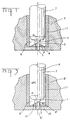
- Figure 1 is a device with a sleeve 7, in an optical fiber end is shown.
- the end of the optical fiber has a bevelled end face on.
- the sleeve 7 has at the end with the end face of the optical fiber end a pin 1, of smaller size Diameter as the sleeve 7.
- the end face of the sleeve 7 So has a step, the pin 1 in one beveled area 2 ends.
- the beveled area 2 is coplanar with the beveled face of the optical fiber end.
- the face is opposite the axis of the optical fiber end or Sleeve, i.e. the optical axis, through an angle ⁇ inclined. It is also possible, for example, that the beveled area 2 and the face of the Optical fiber is spherical in addition to the inclination are arched outwards.
- the sleeve 7 can for example be metallic or made of Be ceramic.
- the end of the optical fiber is with the sleeve 7 in a hollow cylindrical body 3 coaxial to the axis this hollow cylindrical body can be introduced.
- the hollow cylindrical body 3 can be a tube inside, for example, have a ceramic tube 11.
- a such tube is very precise Inner diameter can be produced such that a high-precision guidance of the sleeve 7 in the cylindrical body 3 is reached.
- the cylindrical body 3 instructs one end of a stop 4.
- This stop 4 can Part of the cylindrical body 3 or a separate one Be part of. It has a bore 5 which is coaxial with The axis of the hollow cylindrical body 3 runs.
- the Cone axis coincides with the axis of bore 5. It is particularly advantageous if the angle between the Cone shell and the cone axis ⁇ the angle ⁇ between the end face and the axis of the optical fiber end corresponds.
- the arrangement shown in FIG. 1 makes it possible to to adjust a beveled and possibly spherically ground optical fiber at a certain distance from a certain point on the axis of the hollow cylindrical body.
- the inclined region 2 of the end face of the sleeve 7 abuts against the conical surface of the stop 4.
- the diameter of the bore 5 is therefore smaller than the outside diameter of the pin.
- the clear width of the bore 5 should be larger than the diameter of the optical fiber so as not to damage the end face of the fiber. In order to achieve a high level of accuracy, it makes sense to provide the point of contact between the stop and the inclined area as close as possible to the fiber.
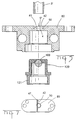
- FIG. 2 shows a use of that in FIG. 1 shown arrangement shown.
- the hollow cylindrical body 3 is part of a metallic Housing 8, which is also a receptacle for one optoelectronic transmitting or receiving element and a has additional optical element.
- the optical element in this case is a spherical lens 10, which in Regarding the axis of the hollow cylindrical body is fixed.
- a lens holder is provided in which is the optoelectronic transmitting or receiving element, for example, a laser 9 is fixed.
- Figures 3 and 4 is a device shown.
- Optical waveguide is introduced, which is in a sleeve 7 is captured and its end 2 inclined to the optical Axis runs.
- the sleeve 7 has one at its end Pin 1 with a smaller diameter, the The face is inclined.
- the beveled area 2 runs coplanar with the beveled face of the Optical fiber end.
- the positioning device has a cylindrical body 3 '.
- the Optical fiber end with the sleeve is in these hollow cylindrical body 3 'coaxial to the axis of the hollow cylindrical body 3 'can be introduced.
- the hollow cylindrical body 3 ' has a tube inside, for example, a ceramic tube 11 '.
- the cylindrical body 3 ' At its end the cylindrical body 3 'has a stop 4'.
- the stop 4 ' is a separate one Part trained, but it can also be part of cylindrical body 3 '.
- the stop 4 ' points a bore 5 ', which is coaxial to the axis of the hollow cylindrical body 3 '.
- the stop 4 ' is structured as follows: It essentially exists from two areas, the division of the two Areas through the optical axis A. The one The area has a partial plane 42 as the surface is aligned perpendicular to the optical axis, while the second region has a partial plane 41 which according to the angle of the face of the Optical fiber end is inclined.
- Figure 4 is the device shown in Figure 3 shown again, but there is an optical fiber end, which is contained in a sleeve 7 ', shown End face perpendicular to the optical axis A.
- the arrangement further has the advantage of being a Optical fiber end with an inclined face only can be introduced into the device in one orientation is. This is advantageous in that it does so can be ensured that a reproducible Coupling can take place.
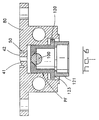
- FIGS. 5 to 7 now show an inventive one Execution of an arrangement according to FIGS. 3 and 4 shown. It is the use of an arrangement for Coupling an optical fiber end to optoelectronic transmitting or receiving element shown.
- a housing 80 is provided, which the Bore 5 'and the stop 4, and a Opening for receiving a lens holder 120, and an attitude 121 for the optoelectronic transmission or Receiving element.
- the hollow cylindrical body 3 ' is made for example from a ceramic tube that into a corresponding groove 50 is made in the housing 80. How can be seen from the supervision in FIG Surface of the housing 80 in some areas with a Cross-section triangular groove through which the to optical axis inclined sub-plane 41 is formed.
- the ball lens is located in the ball lens holder 120, which in a corresponding cylindrical opening of the Housing 80 can be introduced.
- An attachment of the Ball lens holder 120 in the housing 80 is made by a press fit, as shown in Figure 6 by the arrow with the designation PF is indicated. That’s it possible, the ball lens in its longitudinal position to adjust to the end face of the optical fiber.
- the optoelectronic element is on another Bracket 121 attached relative to the bracket of the Ball lens 120 in the directions perpendicular to the optical Axis can be moved.
Landscapes
- Physics & Mathematics (AREA)
- General Physics & Mathematics (AREA)
- Optics & Photonics (AREA)
- Optical Couplings Of Light Guides (AREA)
- Mechanical Coupling Of Light Guides (AREA)
Priority Applications (1)
| Application Number | Priority Date | Filing Date | Title |
|---|---|---|---|
| EP99108311A EP0933661A3 (fr) | 1995-12-22 | 1996-12-20 | Dispositif pour fixer et positionner un bout de fibre optique et utilisation |
Applications Claiming Priority (6)
| Application Number | Priority Date | Filing Date | Title |
|---|---|---|---|
| DE1995148502 DE19548502A1 (de) | 1995-12-22 | 1995-12-22 | Vorrichtung zum Fixieren und Positionieren eines Lichtleitfaserendes und Verwendung |
| DE19548502 | 1995-12-22 | ||
| EP96116751 | 1996-10-18 | ||
| EP96116751 | 1996-10-18 | ||
| EP99108311A EP0933661A3 (fr) | 1995-12-22 | 1996-12-20 | Dispositif pour fixer et positionner un bout de fibre optique et utilisation |
| EP96940694A EP0868672B1 (fr) | 1995-12-22 | 1996-12-20 | Dispositif pour fixer et positionner une extremite de fibre optique et utilisation dudit dispositif |
Related Parent Applications (1)
| Application Number | Title | Priority Date | Filing Date |
|---|---|---|---|
| EP96940694A Division EP0868672B1 (fr) | 1995-12-22 | 1996-12-20 | Dispositif pour fixer et positionner une extremite de fibre optique et utilisation dudit dispositif |
Publications (2)
| Publication Number | Publication Date |
|---|---|
| EP0933661A2 true EP0933661A2 (fr) | 1999-08-04 |
| EP0933661A3 EP0933661A3 (fr) | 2000-06-14 |
Family
ID=26021655
Family Applications (2)
| Application Number | Title | Priority Date | Filing Date |
|---|---|---|---|
| EP96940694A Expired - Lifetime EP0868672B1 (fr) | 1995-12-22 | 1996-12-20 | Dispositif pour fixer et positionner une extremite de fibre optique et utilisation dudit dispositif |
| EP99108311A Withdrawn EP0933661A3 (fr) | 1995-12-22 | 1996-12-20 | Dispositif pour fixer et positionner un bout de fibre optique et utilisation |
Family Applications Before (1)
| Application Number | Title | Priority Date | Filing Date |
|---|---|---|---|
| EP96940694A Expired - Lifetime EP0868672B1 (fr) | 1995-12-22 | 1996-12-20 | Dispositif pour fixer et positionner une extremite de fibre optique et utilisation dudit dispositif |
Country Status (4)
| Country | Link |
|---|---|
| EP (2) | EP0868672B1 (fr) |
| JP (1) | JP2000502814A (fr) |
| DE (1) | DE59605522D1 (fr) |
| WO (1) | WO1997023795A2 (fr) |
Families Citing this family (3)
| Publication number | Priority date | Publication date | Assignee | Title |
|---|---|---|---|---|
| JP5366055B2 (ja) * | 2009-10-13 | 2013-12-11 | 株式会社フジクラ | 光コネクタ挿抜工具 |
| JP7174412B2 (ja) * | 2019-02-27 | 2022-11-17 | 本多通信工業株式会社 | 光レセプタクル |
| JP7202038B2 (ja) | 2019-02-27 | 2023-01-11 | 本多通信工業株式会社 | 光レセプタクル |
Family Cites Families (8)
| Publication number | Priority date | Publication date | Assignee | Title |
|---|---|---|---|---|
| JPS63179304A (ja) * | 1987-01-20 | 1988-07-23 | Fuji Electric Co Ltd | 反射形光応用センサシステムの光コネクタ |
| DE3910166A1 (de) * | 1989-03-29 | 1990-10-11 | Siemens Ag | Optische koppelvorrichtung und verfahren zu deren herstellung |
| US4979791A (en) * | 1989-12-08 | 1990-12-25 | Amp Incorporated | Laser diode connector assembly |
| US5309542A (en) * | 1991-09-18 | 1994-05-03 | International Business Machines Corporation | Fiber optic transmitter modification for improved extinction ratio |
| DE69210340T2 (de) * | 1991-09-25 | 1997-01-02 | Nippon Electric Co | Optischer Modul |
| DE4136893A1 (de) * | 1991-11-09 | 1993-05-13 | Ant Nachrichtentech | Optische sende- und empfangsanordnung |
| CA2088612C (fr) * | 1992-02-03 | 2003-04-15 | Yoshiki Kuhara | Detecteur de lumiere a semiconducteur |
| GB9303169D0 (en) * | 1993-02-17 | 1993-03-31 | Bt & D Technologies Ltd | Optical connector |
-
1996
- 1996-12-20 JP JP09523480A patent/JP2000502814A/ja active Pending
- 1996-12-20 DE DE59605522T patent/DE59605522D1/de not_active Expired - Fee Related
- 1996-12-20 WO PCT/IB1996/001455 patent/WO1997023795A2/fr not_active Ceased
- 1996-12-20 EP EP96940694A patent/EP0868672B1/fr not_active Expired - Lifetime
- 1996-12-20 EP EP99108311A patent/EP0933661A3/fr not_active Withdrawn
Also Published As
| Publication number | Publication date |
|---|---|
| WO1997023795A2 (fr) | 1997-07-03 |
| EP0868672B1 (fr) | 2000-06-28 |
| DE59605522D1 (de) | 2000-08-03 |
| EP0933661A3 (fr) | 2000-06-14 |
| JP2000502814A (ja) | 2000-03-07 |
| WO1997023795A3 (fr) | 1997-09-12 |
| EP0868672A2 (fr) | 1998-10-07 |
Similar Documents
| Publication | Publication Date | Title |
|---|---|---|
| DE69914542T2 (de) | Einstellbares optisches Dämpfungsglied mit Verriegelungsratsche | |
| DE3214582A1 (de) | Vorrichtung zum ausrichten einer optischen faser nach einer kollimationslinse | |
| EP0864888A1 (fr) | Connecteur pour une connexion enfichable optique et procédé pour sa fabrication | |
| WO2008046414A1 (fr) | Dispositif d'injection de lumière dans une fibre optique | |
| DE69636186T2 (de) | Vorrichtung mit einer Linse zum optischen Verbinden eines optischen Elements, zum Beispiel einer optischen Faser, mit einem anderen optischen Element | |
| DE2842535A1 (de) | Abzweigelement | |
| DE69328958T2 (de) | Faseroptische Justiervorrichtung | |
| DE102023112682A1 (de) | Faseroptischer verbinder mit strahlaufweitung und kabelmanagementsystem | |
| WO2003071329A1 (fr) | Raccord optique enfichable | |
| EP0813693B1 (fr) | Dispositif a episser permettant de souder des fibres optiques | |
| DE68919029T2 (de) | Reflexionsarmes Endteil eines Kugellinsensteckers. | |
| DE2923490C2 (de) | Stecker für Lichtleitungsverbinder | |
| DE2711171A1 (de) | Endstueck einer lichtleitstabvorrichtung | |
| DE4221040C2 (de) | Verfahren zur Herstellung eines Lichtwellenleitersteckers | |
| DE69220614T2 (de) | Koppler für ein Laserstrahlzuführsystem | |
| EP0868672B1 (fr) | Dispositif pour fixer et positionner une extremite de fibre optique et utilisation dudit dispositif | |
| DE2746497A1 (de) | Lichtleiteranschluss fuer optische koppelanordnungen | |
| DE2708014C3 (de) | Stecker zur Ankopplung eines Einzellichtwellenleiters an einen anderen Einzellichtwellenleiter oder an einen Lichtsender oder Lichtempfänger | |
| EP0354173A1 (fr) | Procédé pour centrer une fibre optique dans un embout et embout fabriqué selon ce procédé | |
| EP0898186A1 (fr) | Connecteur pour fibres optiques et cables | |
| DE8706844U1 (de) | Stecker für Lichtwellenleiter | |
| DE4031747C2 (fr) | ||
| DE2742357C2 (de) | Steckvorrichtung für Lichtwellenleiter | |
| DE3514374A1 (de) | Verbindungshuelse zur einkopplung eines laserstrahles in einen optischen wellenleiter | |
| DE19548502A1 (de) | Vorrichtung zum Fixieren und Positionieren eines Lichtleitfaserendes und Verwendung |
Legal Events
| Date | Code | Title | Description |
|---|---|---|---|
| PUAI | Public reference made under article 153(3) epc to a published international application that has entered the european phase |
Free format text: ORIGINAL CODE: 0009012 |
|
| AC | Divisional application: reference to earlier application |
Ref document number: 868672 Country of ref document: EP |
|
| AK | Designated contracting states |
Kind code of ref document: A2 Designated state(s): DE FR GB |
|
| PUAL | Search report despatched |
Free format text: ORIGINAL CODE: 0009013 |
|
| AK | Designated contracting states |
Kind code of ref document: A3 Designated state(s): DE FR GB |
|
| RIC1 | Information provided on ipc code assigned before grant |
Free format text: 7G 02B 6/42 A, 7G 02B 6/38 B |
|
| 17P | Request for examination filed |
Effective date: 20001129 |
|
| 17Q | First examination report despatched |
Effective date: 20010430 |
|
| STAA | Information on the status of an ep patent application or granted ep patent |
Free format text: STATUS: THE APPLICATION IS DEEMED TO BE WITHDRAWN |
|
| 18D | Application deemed to be withdrawn |
Effective date: 20011110 |