EP0933792B1 - Betätigungs vorrichtung mit ziffer blatt - Google Patents
Betätigungs vorrichtung mit ziffer blatt Download PDFInfo
- Publication number
- EP0933792B1 EP0933792B1 EP97944198A EP97944198A EP0933792B1 EP 0933792 B1 EP0933792 B1 EP 0933792B1 EP 97944198 A EP97944198 A EP 97944198A EP 97944198 A EP97944198 A EP 97944198A EP 0933792 B1 EP0933792 B1 EP 0933792B1
- Authority
- EP
- European Patent Office
- Prior art keywords
- knob
- light
- dial
- knob dial
- led
- Prior art date
- Legal status (The legal status is an assumption and is not a legal conclusion. Google has not performed a legal analysis and makes no representation as to the accuracy of the status listed.)
- Expired - Lifetime
Links
Images



Classifications
-
- H—ELECTRICITY
- H01—ELECTRIC ELEMENTS
- H01H—ELECTRIC SWITCHES; RELAYS; SELECTORS; EMERGENCY PROTECTIVE DEVICES
- H01H19/00—Switches operated by an operating part which is rotatable about a longitudinal axis thereof and which is acted upon directly by a solid body external to the switch, e.g. by a hand
- H01H19/02—Details
- H01H19/025—Light-emitting indicators
Definitions
- the present invention relates to a dial operation device having a structure of informing an operator of a rotational position of a knob dial when a plurality of display sections provided in the knob dial are selectively illuminated.
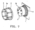
- Fig. 7 is a view showing a conventional structure of the above dial operation device.
- a knob base 2 is fixed onto a printed circuit board 1.
- a knob dial 3 is attached onto an outer circumferential surface of this knob base 2.
- This knob dial 3 is provided with a plurality of linear light paths 3a.
- the knob dial 3 there are provided a plurality of display sections 4 arranged at one end portion of each light path 3a, and these display sections 4 transmit light.
- a plurality of light sources 5 which are located on a rotational locus of the display section 4.
- electricity is supplied to a predetermined light source 5 according to a rotational position of the knob dial 3, so that light can be supplied to a predetermined display section 4 via a predetermined light path 3a.
- the predetermined display section 4 is illuminated.
- a plurality of marks 2a on the knob base 2 are selectively indicated, a -rotational condition of the knob dial 3 is informed to an operator.
- the present invention has been accomplished in view of the above circumstances. It is an object of the present invention to provide a dial operation device capable of illuminating a display section to the utmost even in the middle of rotation of the knob dial.
- a dial operation device described in claim 1 comprises: a knob dial to be rotated for operation; a plurality of display sections capable of transmitting light, arranged in the knob dial; a plurality of light sources arranged on rotational loci of the plurality of display sections; a control unit for selectively turning on a light source in the plurality of light sources according to a rotational position of the knob dial; and a plurality of light paths for supplying light, which has been projected by the light sources, to the display sections, arranged in the knob dial, wherein these light paths are formed into a substantial sector-shape, the width of which is extended from the light exit to the light entrance.
- the light path is formed into a substantial sector-shape, and width of the light path is extended from the light exit to the light entrance. Due to the above structure, even if the knob dial is set at an intermediate position, a beam of projection light sent from the light source is projected into the light entrance except for an instant at which a wall section located between the light paths is opposed to the light source. Therefore, the beam of light can be supplied to the display section via the light path, so that the display section can be illuminated to the utmost.
- the control unit operates in such a manner that when the knob dial starts being rotated, a light source corresponding to the next rotational position is turned on while a light source corresponding to the rotational position of the dial knob is kept to be turned on.
- a light source corresponding to the rotational position of the knob dial is turned on, and a light source corresponding to the next rotational position of the knob dial is turned on. Therefore, a beam of projection light sent from the light source corresponding to the next rotational position is supplied to the display section via the light path. Accordingly, the display section corresponding to the next rotational position of the knob dial is illuminated, and a rotational direction of the knob dial is informed.
- this embodiment is a case in which the present invention is applied to a heater controller of an automobile, and this heater controller is attached onto an instrument panel of the automobile.
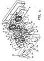
- a bezel 32 made of synthetic resin.
- This bezel 32 is formed into a rectangular box-shape, the rear surface of which is open.
- a printed wiring board 12 is attached to the bezel 32 with screws, and a rear opening of the bezel 32 is covered with a printed wiring board 12 and a cover 11.
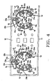
- each holder 13 has six partition walls 13a which are integrated with the holder 13. Only four partition walls 13a are shown in Fig. 5. Between the partition walls 13a, there is formed an LED accommodating section 13b.
- LEDs 15a to 15e corresponding to light sources are accommodated in five LED accommodating sections 13b of each holder 13.
- One of the terminals of each LED is connected to the common circuit pattern 14.
- each common circuit pattern 14 there are provided five power source circuit patterns 16 which are located in an outer circumferential section of each common circuit pattern 14. The other terminal of each LED is connected to the power source pattern 16. Electricity is supplied to LEDs 15a to 15e via the common circuit pattern 14 and the power source circuit pattern 16.
- Knob bases 17, 17 shown in Fig. 5 are made of synthetic resin.
- a cylindrical section 17a is integrally formed in each knob base 17.
- Each cylindrical section 17a corresponds to a moderation member and has a hexagonal cross-section as shown in Fig. 2.
- a screw is inserted into the hole 12a from the rear side. This screw 17b is screwed into the cylindrical section 17a. Due to the foregoing, the knob bases 17, 17 are fixed onto the printed wiring board 12.
- a substantially-cylindrical knob dial 18 made of synthetic resin is pivotally engaged on an outer circumferential surface of each knob base 17.
- a cylindrical knob body 19 made of synthetic resin In the knob dial 18, there is accommodated a cylindrical knob body 19 made of synthetic resin.
- a plurality of spherical sections 21a are formed on a lower surface of each knob dial 18 and on a lower surface of each knob body 19. Due to the above structure, when each knob dial 18 is rotated for operation, the plurality of spherical sections 21a slide on the printed wiring board 12.
- each knob body 19 a leaf spring 22 corresponding to the spring member is accommodated in each knob body 19.
- Each leaf spring 22 is bent and formed into a triangle.
- the engaging sections 22a of the leaf spring 22 are inserted into the three grooves 19b of each knob body 19. Due to the above structure, when each knob dial 18 is rotated for operation, the leaf spring 22 is rotated integrally with the knob body 19.
- each knob dial 18 As shown in Fig. 2, three surfaces of each leaf spring 22 come into surface-contact with predetermined three surfaces of the cylindrical section 17a. Therefore, when each knob dial 18 is rotated and the leaf spring 22 is operated according to the rotation of the knob dial 18, the leaf spring 22 is pushed and deflected by three corners of the cylindrical section 17a. After that, the three corners of each cylindrical section 17a get over the leaf spring 22 and engage with three new surfaces, so that the rotation of each knob dial 18 can be regulated again. Accordingly, each knob dial 18 can be positioned at the interval of 60°. Further, each time the corners of the cylindrical section 17a get over the leaf spring 22 at the interval of 60°, it is possible to provide a feeling of moderation.
- each contact 23 located on the outer circumference is screwed onto a rear surface of each knob dial 18. As shown in Fig. 5, each contact 23 has contact points 23a to 23d. The contact points 23a, 23b on the outer circumferential side come into contact with the common circuit pattern 14, the shape of which is an arc as shown in Fig. 4.
- first detection circuit patterns 24a to 24e which are located on the inner circumferential section of each common circuit pattern 14.
- the contact point 23c of each contact 23 comes into the detection circuit pattern 24a to 24e according to the rotational position of the knob dial 18. Due to the foregoing, the predetermined detection circuit pattern 24a to 24e can be selectively continued to the common circuit pattern 14, and a continuation signal is outputted from the predetermined detection circuit pattern 24a to 24e.
- the contact point 23b of each contact 23 is a dummy contact point which is provided for adjusting the mechanical balance.
- ECU (not shown) corresponding to a control unit is mounted on an automobile.
- This ECU is mainly composed of a microcomputer and operated as follows.
- a rotational position of each knob dial 18 is detected according to the detection circuit pattern 24a to 24e from which a continuation signal is outputted.
- a hot air or cold air blowing position of air control is changed over according to a rotational position of the knob dial located on the left, and a quantity of blowing control air is changed over according to a rotational position of the knob dial 18 located on the right.
- electricity is supplied to a predetermined LED 15a to 15e via the common circuit pattern 14 and the power supply circuit pattern 16, so that light can be emitted from the predetermined LED 15a to 15e.
- a plurality of marks 25 indicating a blowing position of hot air on the front surface of the knob base 17 located on the left
- a plurality of marks 26 indicating a quantity of blowing hot air on the front surface of the knob base 17 located on the right.
- These marks 25, 26 are formed on the knob base 17 by means of laser beam machining and have a property of light transmission.
- a light guide 27 at the rear of the printed wiring board 12 in the cover 11.
- openings for illumination at the rear of the marks 25, 26 on the printed wiring board 12.
- protrusions 27a at the rear of the openings 12b for illumination.
- a plurality of lamps 28 on the rear surface of the printed wiring board 12. These lamps 28 are positioned in the light guide 27. When the plurality of lamps 28 are supplied with electricity by the controlling operation of ECU, light is emitted from the protrusions 27a so that the marks 25, 26 can be illuminated via the openings 12b for illumination.
- an indicator lens 29a to 29f is embedded at a front end portion on a circumferential wall of each knob dial 18.
- These indicator lenses 29a to 29f correspond to- the display sections.
- LEDs 15a to 15e are positioned at the rear of the indicator lenses 29a to 29f, that is, LEDs 15a to 15e are positioned on the locus of rotation. Therefore, as shown in Fig. 2, under the condition that the knob dials 18 are positioned, five predetermined indicator lenses in the indicator lenses 29a to 29f are opposed to LEDs 15a to 15e.
- the indicator lenses 29a to 29f are formed on the knob dials 18 by means of two color formation.
- each light path 30 connects a light entrance 30a, which is open via a rear surface of the knob dial 18, with a light exit 30b which is communicated with the indicator lens 29a to 29f.
- Each light path 30 is formed into a sector-shape in which width is gradually extended from the light exit 30b to the light entrance 30a.
- reference numeral 30c is a light shielding wall section located between the light paths 30.
- each light shielding wall section 30c is opposed to a partition wall 13a of the holder 13. Accordingly, a beam of light projected from a predetermined LED 15a to 15e passes through the light exit 30a and the light entrance 30b and is supplied to a predetermined indicator lens 29a to 29f. Due to the foregoing, the predetermined indicator lens 29a to 29f emits light. Therefore, a plurality of marks 25, 26 are selectively indicated. In accordance with that, a hot air blowing position and a quantity of hot air to be blown out by the knob dial are informed to a driver.
- second detection circuit patterns 31 a1 , 31 a2 to 31 e1 , 31 e2 which are located on an inner circumference of the first detection circuit patterns 24a to 24e.
- the contact point 23d of the contact 23 is located in a gap between the detection circuit patterns 31 a1 , 31 a2 to 31 e1 31 e2 as shown by two-dotted chain lines.
- the contact point 23d of the contact 23 comes into contact with the detection circuit pattern 31 a1 , 31 a2 to 31 e1 , 31 e2 according to the rotational direction of the knob dial 18. Therefore, the detection circuit pattern 31 a1 , 31 a2 to 31 e1 , 31 e2 can be selectively continued to the common circuit pattern 14. Then, as described later, ECU judges a rotational direction of each knob dial 18 according to the detection circuit pattern 31 a1 , 31 a2 to 31 e1 , 31 e2 from which a continuity signal has been outputted.
- the bezel 32 shown in Fig. 5 is made of synthetic resin. As shown in Fig. 3, a plurality of engaging holes 32a are formed on a side plate of the bezel 32. In this case, only one engaging hole 32a is illustrated in the drawing. A plurality of claws 11a are integrally formed on a side plate of the cover 11. In this case, only one claw 11a is illustrated in the drawing.
- each engaging holes 32a are engaged with the claw 11a, so that the bezel 32 can be attached to the cover 11, and the front surface of the printed wiring board 12 is covered with the bezel 32.
- each knob dial 18 protrudes from the opening 32b onto the front surface side.
- a base 33 which is arranged between holders 13.
- rubber contact points 34a, 34b to turn on and off the defrosting mode in which controlled air is blown out onto a windshield.
- rubber contact points 34a, 34b to turn on and off the REC mode in which air is circulated in a chamber.
- rubber contact points 34a, 34b to turn on and off an air conditioner.
- a rectangular opening 32c In the bezel 32, there is formed a rectangular opening 32c. Into this rectangular opening 32c, three operation knobs 35 are attached as shown in Fig. 2. When each knob 35 is pushed for operation, ON-signal is outputted from the rubber contact points 34a and 34b.
- Each operation knob 35 is provided with an indicator lens 35a. As shown in Fig. 3, on the printed wiring board 12, there is provided an LED 35b which is arranged in each operation knob 35. According to the operating condition of the operation knob 35, ECU turns on and off LED 35b, so that each indicator lens 35a can be turned on and off. Therefore, a driver is informed of the operating condition (defrosting mode, REC mode and setting condition of the air conditioner) of each operation knob 35.
- a knob dial 36 which is pivotally attached. According to a rotational position of the knob dial 36, ECU adjusts a temperature of controlled air.
- an operation key 36a which is arranged inside the knob dial 36.
- the automatic control mode is turned on and off.
- a blowing position of controlled air and a quantity of controlled air can be automatically changed over.
- electricity is selectively supplied to LED 15a to 15e irrespective of the rotational position of each knob dial 18, light is emitted from a predetermined indicator lens 29a to 29f via the light entrance 30a and light exit 30b. Due to the foregoing, a changeover condition in which a position of blowing air and a quantity of blowing air are changed over can be informed to a driver.
- the bezel 32 there are provided panels 37a and 37b. On the panels 37a and 37b, there are respectively provided indicator lenses 38a and 38b. When LED (not shown) is turned on and off by ECU, the indicator lenses 38a, 38b are turned on and off. Therefore, the operating condition (setting condition of the automatic control mode) of the operation key 36a can be informed to the driver.
- each knob dial 18 is rotated for operation. Due to the above operation, ECU conducts controlling so that electricity can be supplied to LED 15a to 15e according to the rotational position of each knob dial 18 and a predetermined indicator 29a to 29f can be turned on. In accordance with that, a plurality of marks 25, 26 are selectively indicated. Due to the foregoing, the driver is informed of a rotational condition (hot air blowing position and quantity of hot air) of each knob dial 18.
- the contact point 23c of the contact 23 comes into contact with the first detecting circuit pattern 24d in Fig. 4, and a continuity signal is outputted from the first detecting circuit pattern 24d.
- ECU turns off LED 15c in Fig. 2.
- a beam of projection light sent from LED 15d is supplied to the indicator lens 29c via the light entrance 30a and the light exit 30b. Therefore, only the indicator lens 29c emits light.
- the rotation of the knob dial 18 is regulated. Therefore, when the knob dial 18 is operated and the leaf spring 22 is rotated, the leaf spring 22 is pushed by three corners of the cylindrical section 17a and bent in the same direction as that of pushing. For the above reasons, the rotational resistance of the knob dial 18 is reduced, and an operation feeling of the knob dial 18 becomes light. It is possible to prevent the operation feeling from growing heavy especially at an intermediate position.
- the light path 30 is formed into a sector-shape in which width of the light path 30 is extended from the light exit 30b to the light entrance 30a. Therefore, even when the knob dial 18 is set at an intermediate position, that is, even when the position of the knob dial 18 is not regulated, a beam of projection light sent from LED 15a to 15e is projected into the light entrance 30a except for an instant at which the light shielding wall section 30c is opposed to LED 15a to 15e. Then, the beam of projection light is supplied to the indicator lens 29a to 29f via the light path 30. Therefore, the indicator lens 29a to 29f can be illuminated to the utmost.
- Each wire spring 39 described above is bent into a triangle.
- each wire spring 39 there are formed three engaging sections 39a.
- Each engaging section 39a is inserted into a groove 19b of the knob body 19. Rotation of the knob dial 18 arranged on the left is regulated when two wire springs 39 are engaged with three surfaces of the cylindrical section 17a. Rotation of the knob dial 18 arranged on the right is regulated when one wire spring 39 is engaged with three surfaces of the cylindrical section 17a.
- Two wire springs 39 are used for the knob dial 18 arranged on the left, and one wire spring 39 is used for knob dial 18 arranged on the right. Therefore, an intensity of the knob dial 18 arranged on the left is different from an intensity of the knob dial 18 arranged on the right. Accordingly, it is possible for a driver to distinguish between the two knob dials 18 by a feeling of operation. Therefore, the operation property of the knob dial 18 can be enhanced.
- the wire springs 39 are used for both knob dials 18. Therefore, it is unnecessary to carefully distinguish between both leaf springs 22 when they are attached to the knob dials 18. Accordingly, the assembling property can be enhanced. Unlike a case in which the leaf springs 22 of different types are manufactured, only one type wire spring 39 is used in this embodiment. Therefore, this embodiment is advantageous in that the number of parts can be reduced.
- wire springs 39 are accommodated in both knob bodies 19.
- the present invention is not limited to the above specific embodiment.
- intensities of forces to operate both knob dials 18 may be adjusted.
- the second detection circuit patterns 31 a1 , 31 a2 to 31 e1 , 31 e2 for detecting the rotational directions of the knob dials 18 are formed on the printed wiring board 12.
- the present invention is not limited to the above specific embodiment.
- the second detection circuit patterns 31 a1 , 31 a2 to 31 e1 , 31 e2 may be abolished.
- the contact point of each contact 23 may be also abolished.
- the cylindrical section 17a is fixed to the holder 13, and the leaf spring 22 and the wire spring 39 are rotated integrally with the knob dial 18.
- the present invention is not limited to the above specific embodiment.
- the leaf spring 22 or the wire spring 39 may be fixed to the holder 13, and the cylindrical section 17a may be rotated integrally with the knob dial 18.
- the cylindrical section 17a the cross-section of which is hexagonal, the triangular leaf spring 22 and the wire spring 39 are used and three surfaces of the cylindrical section 17a are engaged with the leaf spring 22 and the wire spring 39.
- the present invention is not limited to the above specific embodiment.
- a linear leaf spring and wire spring may be used, and one surface of the cylindrical section 17a may be engaged with the leaf spring and the wire spring.
- a rotational position of the knob dial 18 is regulated at the regular interval of 60°.
- a rotational position of the knob dial 18 may be regulated at the regular interval of 30°.
- a cross-section of the cylindrical section 17a may be formed into a dodecagon, and the leaf spring 22 and the wire spring 39 may be formed into hexagons.
- the present invention is applied to a heater controller of an automobile.
- the present invention is not limited to the above specific embodiment.
- the essential point is that the present invention can be applied to all dial operation devices having rotational knob dials.
- the dial operation device of the present invention can provide the following effects.
- the light path is formed into a sector-shape in which width of the light path is extended from the light exit to the light entrance. Due to the above structure, even if the knob dial is set at an intermediate position, a beam of projection light can be supplied to the display section from the light source via the light path. Accordingly, the display section can be illuminated to the utmost.
Landscapes
- Rotary Switch, Piano Key Switch, And Lever Switch (AREA)
- Switch Cases, Indication, And Locking (AREA)
Claims (2)
- Anzeige- Betätigungsvorrichtung mit:eingerichtet in der Knopfbetätigung, zu übertragen;einem Knopfwählkörper (18), der zur Betätigung gedreht wird;einer Mehrzahl von Anzeigeabschnitten (25), die in der Lage sind, Licht zu übertragen, angeordnet in dem Knopfwählkörper,einer Mehrzahl von Lichtquellen (15), angeordnet in Drehpositionen der Mehrzahl von Anzeigeabschnitten;einer Steuereinheit zum wahlweisen Einschalten einer Lichtquelle in der Mehrzahl von Lichtquellen entsprechend einer Drehposition des Knopfwählkörpers; undeiner Mehrzahl von Lichtwegen (30) zum Zuführen von Licht, das durch die Lichtquellen zu den Anzeigeabschnitten projiziert worden ist, angeordnet in dem Knopfwählkörper, wobei diese Lichtwege in einer im wesentlichen Sektorform gebildet sind, deren Breite sich von einem Lichtaustritt zu einem Lichteintritt erstreckt.
- Anzeige- Betätigungsvorrichtung nach Anspruch 1, wobei die Steuereinheit in solch einer Weise arbeitet, dass dann, wenn der Knopfwählkörper (18) beginnt gedreht zu werden, eine Lichtquelle, die der nächsten Drehposition entspricht, eingeschaltet wird, während eine Lichtquelle, die der Drehposition des Knopfwählkörpers entspricht, eingeschaltet bleibt.
Applications Claiming Priority (3)
| Application Number | Priority Date | Filing Date | Title |
|---|---|---|---|
| JP27243196 | 1996-10-15 | ||
| JP27243196A JP3576720B2 (ja) | 1996-10-15 | 1996-10-15 | ダイアル操作装置 |
| PCT/JP1997/003850 WO1998016940A1 (en) | 1996-10-15 | 1997-10-15 | Dial operating apparatus |
Publications (3)
| Publication Number | Publication Date |
|---|---|
| EP0933792A1 EP0933792A1 (de) | 1999-08-04 |
| EP0933792A4 EP0933792A4 (de) | 2000-01-05 |
| EP0933792B1 true EP0933792B1 (de) | 2003-04-09 |
Family
ID=17513825
Family Applications (1)
| Application Number | Title | Priority Date | Filing Date |
|---|---|---|---|
| EP97944198A Expired - Lifetime EP0933792B1 (de) | 1996-10-15 | 1997-10-15 | Betätigungs vorrichtung mit ziffer blatt |
Country Status (5)
| Country | Link |
|---|---|
| US (1) | US6176589B1 (de) |
| EP (1) | EP0933792B1 (de) |
| JP (1) | JP3576720B2 (de) |
| DE (1) | DE69720753T2 (de) |
| WO (1) | WO1998016940A1 (de) |
Families Citing this family (28)
| Publication number | Priority date | Publication date | Assignee | Title |
|---|---|---|---|---|
| US6522875B1 (en) * | 1998-11-17 | 2003-02-18 | Eric Morgan Dowling | Geographical web browser, methods, apparatus and systems |
| DE20010428U1 (de) * | 2000-06-09 | 2000-08-17 | Mannesmann VDO AG, 60388 Frankfurt | Anordnung zur Beleuchtung des Stellknopfes eines Eingabeaggregates mittels Durchlicht |
| US6471648B1 (en) * | 2000-07-17 | 2002-10-29 | Acuson Corporation | Medical diagnostic ultrasound imaging system with a rotatable user interface element having a non-rotatable indicator |
| US6345898B1 (en) * | 2000-12-05 | 2002-02-12 | Atico International Usa, Inc | Illuminated pad lock |
| DE10202049A1 (de) * | 2002-01-18 | 2003-07-31 | Faude Consulting Gmbh R | Schaltanordnung für eine Haushaltsmaschine oder dergleichen |
| DE60230738D1 (de) * | 2002-08-13 | 2009-02-26 | Vestel Elekt Sanayi Ve Ticaret | Funktionsanzeige zum Anzeigen des Zustandes einer Vorrichtung |
| DE10243629A1 (de) * | 2002-09-19 | 2004-04-08 | Electrolux Home Products Corporation N.V. | Drehknebel, insbesondere versenkbarer Drehknebel für Haushaltsgeräte |
| JP3970756B2 (ja) * | 2002-12-03 | 2007-09-05 | アルプス電気株式会社 | 照光式スイッチ装置 |
| US6733146B1 (en) * | 2003-01-10 | 2004-05-11 | Pat J. Vastano | Illuminated knob for indicating the operative condition of an appliance |
| DE20314364U1 (de) | 2003-09-16 | 2004-02-26 | Trw Automotive Electronics & Components Gmbh & Co. Kg | Drehschalter in einem Kraftfahrzeug |
| US7633485B2 (en) * | 2004-01-29 | 2009-12-15 | Chrysler Group Llc | Single knob multifunction controller and display unit |
| CN1965138B (zh) * | 2004-03-11 | 2011-09-07 | 总锁有限责任公司 | 锁用照明机构 |
| JP4367850B2 (ja) * | 2004-09-27 | 2009-11-18 | シチズン電子株式会社 | 照光式スイッチ |
| JP4636546B2 (ja) * | 2005-08-02 | 2011-02-23 | 株式会社東海理化電機製作所 | 車両用の空調スイッチ装置 |
| FR2889767B1 (fr) * | 2005-08-11 | 2011-05-13 | Valeo Systemes Thermiques | Retro eclairage d'un bouton de commande avec guide lumiere. |
| US7222979B1 (en) * | 2005-11-09 | 2007-05-29 | Cfm Corporation | Illuminated dial |
| US20070113600A1 (en) * | 2005-11-21 | 2007-05-24 | Marcelle Jesse A | Locking mechanism |
| JP4789900B2 (ja) * | 2007-10-02 | 2011-10-12 | 帝国通信工業株式会社 | 照光機能付き複合電子部品 |
| JP5209937B2 (ja) * | 2007-10-26 | 2013-06-12 | 株式会社東海理化電機製作所 | 操作装置 |
| KR200450946Y1 (ko) | 2008-07-15 | 2010-11-11 | 주식회사 현대오토넷 | 볼륨노브의 조명장치 |
| US8178802B2 (en) * | 2008-07-31 | 2012-05-15 | Electrolux Home Products, Inc. | Unitized appliance control panel assembly and components of the assembly |
| DE102009057951B4 (de) * | 2009-12-11 | 2013-07-11 | GM Global Technology Operations LLC (n. d. Ges. d. Staates Delaware) | Beleuchtungseinrichtung für eine Einstellvorrichtung zum Einstellen eines Betriebsparameters in einem Fahrzeug |
| KR101303172B1 (ko) * | 2012-02-29 | 2013-09-09 | 알프스 덴키 가부시키가이샤 | 조광스위치 어셈블리 |
| JP5871669B2 (ja) * | 2012-03-13 | 2016-03-01 | アルプス電気株式会社 | 照光機能付き入力装置 |
| JP6783530B2 (ja) | 2016-03-07 | 2020-11-11 | アルプスアルパイン株式会社 | 表示装置及びそれを備えた操作スイッチ |
| CN106783330A (zh) * | 2016-12-21 | 2017-05-31 | 广东金莱特电器股份有限公司 | 一种带灯光显示的旋转开关 |
| US10345514B2 (en) * | 2017-02-22 | 2019-07-09 | Haier Us Appliance Solutions, Inc. | Appliance and illuminated knob assembly |
| EP3614931B1 (de) | 2017-04-28 | 2025-11-19 | Stryker Corporation | System und verfahren zur anzeige der zuweisung von konsolenbasierten chirurgischen systemen |
Family Cites Families (9)
| Publication number | Priority date | Publication date | Assignee | Title |
|---|---|---|---|---|
| JPS5324474U (de) * | 1976-08-10 | 1978-03-01 | ||
| JPS5324474A (en) | 1976-08-18 | 1978-03-07 | Santo Tekkosho Kk | Method of desizing* scouring and mercerizing textile fabric |
| CH660557A5 (fr) | 1984-10-26 | 1987-05-15 | Nestle Sa | Composition anti-bacterienne et procede de preparation de ses constituants actifs. |
| JPS61103829U (de) * | 1984-12-13 | 1986-07-02 | ||
| US4761715A (en) * | 1987-03-25 | 1988-08-02 | Beede Electrical Instrument Co., Inc. | Laser pointer |
| DE3808770C2 (de) | 1988-03-16 | 1996-10-24 | Teves Gmbh Alfred | Beleuchtbare Vorrichtung |
| JPH0324232A (ja) | 1989-06-20 | 1991-02-01 | Nissan Motor Co Ltd | 歯車の高周波焼入方法 |
| JPH0324232U (de) * | 1989-07-19 | 1991-03-13 | ||
| US5171080A (en) * | 1991-05-28 | 1992-12-15 | Allied-Signal Inc. | Method of reducing light leakage from internally illuminated panels |
-
1996
- 1996-10-15 JP JP27243196A patent/JP3576720B2/ja not_active Expired - Fee Related
-
1997
- 1997-10-15 EP EP97944198A patent/EP0933792B1/de not_active Expired - Lifetime
- 1997-10-15 DE DE69720753T patent/DE69720753T2/de not_active Expired - Fee Related
- 1997-10-15 WO PCT/JP1997/003850 patent/WO1998016940A1/ja not_active Ceased
- 1997-10-15 US US09/284,498 patent/US6176589B1/en not_active Expired - Fee Related
Also Published As
| Publication number | Publication date |
|---|---|
| DE69720753D1 (de) | 2003-05-15 |
| WO1998016940A1 (en) | 1998-04-23 |
| DE69720753T2 (de) | 2004-02-05 |
| EP0933792A1 (de) | 1999-08-04 |
| JP3576720B2 (ja) | 2004-10-13 |
| JPH10116536A (ja) | 1998-05-06 |
| US6176589B1 (en) | 2001-01-23 |
| EP0933792A4 (de) | 2000-01-05 |
Similar Documents
| Publication | Publication Date | Title |
|---|---|---|
| EP0933792B1 (de) | Betätigungs vorrichtung mit ziffer blatt | |
| EP1518726B1 (de) | Betätigungsvorrichtung einer Kraftfahrzeugklimaanlage | |
| US7213952B2 (en) | Interior illuminator for automobile | |
| EP1518728B1 (de) | Betätigungsvorrichtung einer Kraftfahrzeugklimaanlage | |
| US6966663B2 (en) | Automotive instrument | |
| US6207913B1 (en) | Operation switch | |
| US7811160B2 (en) | Operating device of vehicle air conditioner | |
| US7091434B2 (en) | Dial switch having an ornamental colored ring | |
| EP0933793B1 (de) | Betätigungsvorrichtung für wählscheibe | |
| US6155691A (en) | Light illuminating type manipulation and display apparatus | |
| KR20050013123A (ko) | 자동차 부품 작동 요소 | |
| JP2002352671A (ja) | 車両用コンビネーションスイッチ | |
| US7067752B2 (en) | Seesaw button of heater control unit | |
| US6087601A (en) | Modular multi-purpose switch | |
| JP4763352B2 (ja) | メータ内インジケータ照明装置 | |
| US20240294113A9 (en) | Vehicle door light assembly | |
| KR100813760B1 (ko) | 차량의 컨트롤모드 조명구조 | |
| JP3177377B2 (ja) | 表示装置 | |
| KR200353637Y1 (ko) | 자동차용 공조패널의 조명장치 | |
| JP2000311552A (ja) | 操作ユニット | |
| JP2502702Y2 (ja) | 自動変速機のシフトレバ―用照明装置 | |
| KR20000007415U (ko) | 자동차의 계기판 조명장치 | |
| JPH08161956A (ja) | 光源ユニット及び該光源ユニットを内蔵した照明装置付きスイッチ | |
| KR20040086862A (ko) | 자동차용 복합식 스위치의 시인성 향상 구조 | |
| JPS63102121A (ja) | 照明式スイツチ盤 |
Legal Events
| Date | Code | Title | Description |
|---|---|---|---|
| PUAI | Public reference made under article 153(3) epc to a published international application that has entered the european phase |
Free format text: ORIGINAL CODE: 0009012 |
|
| 17P | Request for examination filed |
Effective date: 19990414 |
|
| AK | Designated contracting states |
Kind code of ref document: A1 Designated state(s): DE FR GB SE |
|
| A4 | Supplementary search report drawn up and despatched |
Effective date: 19991123 |
|
| AK | Designated contracting states |
Kind code of ref document: A4 Designated state(s): DE FR GB SE |
|
| GRAH | Despatch of communication of intention to grant a patent |
Free format text: ORIGINAL CODE: EPIDOS IGRA |
|
| GRAH | Despatch of communication of intention to grant a patent |
Free format text: ORIGINAL CODE: EPIDOS IGRA |
|
| GRAA | (expected) grant |
Free format text: ORIGINAL CODE: 0009210 |
|
| AK | Designated contracting states |
Designated state(s): DE FR GB SE |
|
| REG | Reference to a national code |
Ref country code: GB Ref legal event code: FG4D |
|
| REG | Reference to a national code |
Ref country code: SE Ref legal event code: TRGR |
|
| ET | Fr: translation filed | ||
| PLBE | No opposition filed within time limit |
Free format text: ORIGINAL CODE: 0009261 |
|
| STAA | Information on the status of an ep patent application or granted ep patent |
Free format text: STATUS: NO OPPOSITION FILED WITHIN TIME LIMIT |
|
| 26N | No opposition filed |
Effective date: 20040112 |
|
| PGFP | Annual fee paid to national office [announced via postgrant information from national office to epo] |
Ref country code: SE Payment date: 20041006 Year of fee payment: 8 |
|
| PGFP | Annual fee paid to national office [announced via postgrant information from national office to epo] |
Ref country code: DE Payment date: 20041007 Year of fee payment: 8 |
|
| PGFP | Annual fee paid to national office [announced via postgrant information from national office to epo] |
Ref country code: FR Payment date: 20041008 Year of fee payment: 8 |
|
| PGFP | Annual fee paid to national office [announced via postgrant information from national office to epo] |
Ref country code: GB Payment date: 20041013 Year of fee payment: 8 |
|
| PG25 | Lapsed in a contracting state [announced via postgrant information from national office to epo] |
Ref country code: GB Free format text: LAPSE BECAUSE OF NON-PAYMENT OF DUE FEES Effective date: 20051015 |
|
| PG25 | Lapsed in a contracting state [announced via postgrant information from national office to epo] |
Ref country code: SE Free format text: LAPSE BECAUSE OF NON-PAYMENT OF DUE FEES Effective date: 20051016 |
|
| PG25 | Lapsed in a contracting state [announced via postgrant information from national office to epo] |
Ref country code: DE Free format text: LAPSE BECAUSE OF NON-PAYMENT OF DUE FEES Effective date: 20060503 |
|
| EUG | Se: european patent has lapsed | ||
| GBPC | Gb: european patent ceased through non-payment of renewal fee |
Effective date: 20051015 |
|
| PG25 | Lapsed in a contracting state [announced via postgrant information from national office to epo] |
Ref country code: FR Free format text: LAPSE BECAUSE OF NON-PAYMENT OF DUE FEES Effective date: 20060630 |
|
| REG | Reference to a national code |
Ref country code: FR Ref legal event code: ST Effective date: 20060630 |