EP0933794A2 - Elektrischer Sicherheitsschalter - Google Patents
Elektrischer Sicherheitsschalter Download PDFInfo
- Publication number
- EP0933794A2 EP0933794A2 EP99101984A EP99101984A EP0933794A2 EP 0933794 A2 EP0933794 A2 EP 0933794A2 EP 99101984 A EP99101984 A EP 99101984A EP 99101984 A EP99101984 A EP 99101984A EP 0933794 A2 EP0933794 A2 EP 0933794A2
- Authority
- EP
- European Patent Office
- Prior art keywords
- cam
- actuator
- switch according
- casing
- electric switch
- Prior art date
- Legal status (The legal status is an assumption and is not a legal conclusion. Google has not performed a legal analysis and makes no representation as to the accuracy of the status listed.)
- Granted
Links
Images


Classifications
-
- H—ELECTRICITY
- H01—ELECTRIC ELEMENTS
- H01H—ELECTRIC SWITCHES; RELAYS; SELECTORS; EMERGENCY PROTECTIVE DEVICES
- H01H27/00—Switches operated by a removable member, e.g. key, plug or plate; Switches operated by setting members according to a single predetermined combination out of several possible settings
- H01H27/002—Switches operated by a removable member, e.g. key, plug or plate; Switches operated by setting members according to a single predetermined combination out of several possible settings wherein one single insertion movement of a key comprises an unlocking stroke and a switch actuating stroke, e.g. security switch for safety guards
- H01H2027/005—Switches operated by a removable member, e.g. key, plug or plate; Switches operated by setting members according to a single predetermined combination out of several possible settings wherein one single insertion movement of a key comprises an unlocking stroke and a switch actuating stroke, e.g. security switch for safety guards the key receiving part having multiple openings to allow keys from different directions to operate the switch
Definitions
- the present invention relates to an electric safety switch, especially for electric power supply circuits for machines and industrial plants.
- Electric switches of the above-mentioned type comprise essentially a casing with at least two slots for inserting an actuating key of pre-defined shape, at least a couple of electric contacts placed in the casing and displaceable between a closed position, when the actuator is connected, and an open position when the actuator is disconnected, a cam placed inside the casing and operatively connected to the electric contacts to displace and commute them, said cam being pivotable around a first axis when inserting the actuator in one of the slots.
- the switch is provided with blocking means to prevent cam rotation and subsequent movement of electric contacts, and elastic means adapted to maintain the blocking means in a stopping position of the cam when the actuator is disconnected from the casing.
- the switch casing is fixed to a stationery part of the machine or plant, for instance to a control cubicle frame, while the key actuator is fixed on a moving part, like the cubicle door.
- opening the cubicle door will commute the electric contacts inside the casing and open the electric power supply circuit of the machine or plant.
- a drawback of this known safety switches lies in the relatively complex and miniaturised cam blocking mechanisms, especially if there are more than one actuator input opening, which reduce mechanical strength and switch reliability.
- actuator input detecting mechanisms are subject to sudden displacements and are susceptible of rupture especially if they are guided in a translating movement.
- the blocking means of those known switches generally comprise one ore more slides placed at the cam sides and able to move along linear guiding means.
- the slides interact together and with the cam by means of inclined planes which produce high friction forces and are subject to seizures due to dirt settled on the sliding surfaces.
- Such slides are subject to high wear.
- mutually disposed multiple disc solutions also are subject to seizures because of the dirt on the contact surfaces.
- the simultaneous rotation of the discs caused by their reciprocal seizure prevents proper functioning of the switch.
- switches provide only one input opening for the actuator, thus limiting flexibility in the use of the device.
- the main object of the present invention is to eliminate, or at least to reduce, the above-mentioned drawbacks by providing a safety switch with high flexibility of use, reliability and long operating life.
- a particular object is to provide a safety switch which is substantially not dirt sensitive.
- Another object of the invention is to provide a safety switch with a simplified structure, and a limited number of parts, so as to be easy to assemble and economically advantageous.
- the blocking means comprise at least a lever element pivotally connected on a second axis distal from the first one and positioned so as to operate on one cam side.
- the second pivot axis of the lever element is substantially parallel to the cam pivot axis. This produces an important simplification and consequently more reliability and longer operational life.
- every lever element has an actuating portion that interacts with the actuator.
- the actuation portion of each lever element is provided with rounded edges that face each of the casing openings to operate smoothly with the actuator at the moment of the introduction in the casing.
- the cam is provided with at least one engagement element, preferably positioned on one lateral side of the cam and it is constituted by a radial protrusion.
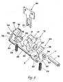
- the switch according to the invention globally referenced as 1, comprises a casing 2 composed of a lower body 3 and upper head 4, adapted to be reciprocally coupled and fixed to a fixed part of a machine or plant, for example to a control cubicle frame.
- the lower body 3 contains a first pair of fixed contacts respectively referenced as 5, 5', for example placed serially on the electric power line of the machine, and a second series of fixed contacts 6, 6', for example placed in series on the electric power line of an optical and/or acoustic alarm.
- Two pairs of mobile contacts respectively referenced as 7,7' and 8, 8' united by respective links 9, 10 are mounted on a shaft 11 slidably guided along a longitudinal axis V by appropriate seats.
- contacts 7, 7', 8, 8' can be displaced between a closed position of contacts 5, 5' and simultaneous opening of contacts 6, 6', as shown in Fig. 1, and an open position of contacts 5, 5' and simultaneous closing of contacts 6, 6', as shown in Fig. 2.
- a compression spring 13 operates on the lower extremity 12 of the moving shaft 11 to push the upper extremity 14 of the shaft 11 against a cam external profile, globally referenced as 15.
- Cam 15 is pivotally mounted on a first rotation axis H defined by a pin 16 inserted in the head 4 and is provided on its periphery with a pair of appropriately shaped hollows 17, 17'.
- the head 4 is provided with two slots 18, 19 made on two adjacent faces of the head 4, for insertion of an actuator 20, having the shape of a key, along two mutually perpendicular directions A and B.
- the key-shaped actuator 20 can be solidarily coupled to a fixed machine part, for instance a cubicle door, and has an end part 21 of special shape interrupted in its centre to cooperate at the input and output with cavities 17, 17' of cam 15.
- the actuator will be inserted in the slot 18 or 19 made in the head 4, interacting with cam 15 to make it rotate.
- Cam 15 operates on the upper extremity 14 of the shaft 11, thus displacing the latter in translation and changing the switch position.
- the switch is provided with blocking means, globally referenced with 22, for preventing rotation of the cam and consequent movement of the contacts, and elastic means 23, for example constituted by compression springs, acting on the blocking means 22 to keep them in a position in which the cam 15 is blocked when the actuator is disconnected from the head 4.
- the blocking means comprise at least one lever element 24 pivotally coupled on a second axis K, distal from the first one and positioned so as to actuate cam 15.
- Axis K is preferably parallel to axis H so that the movements of the lever elements 24, 24' occur in a direction substantially perpendicular to the cam rotation axis H.
- lever elements 24, 24' are provided, arranged at the opposite faces of cam 15 and pivotally connected on a pin 25 coinciding with axis K.
- Each lever element 24, 24' comprises an actuating portion 26, 26' for interacting with the actuator and a blocking portion 27, 27' for interacting with cam 15.
- each actuating portion 26, 26' has rounded edges 28, 28' and 29, 29' facing their respective slots 18, 19 in the head 4, to slidingly interact with actuator 20 when it is inserted.
- cam 15 is provided with engagement elements.
- the engagement elements are positioned on the lateral faces of the cam 15 and are constituted by a radial protrusion 30 extending from an axial hub 31 solidarily fixed to the cam.
- Actuating portions 26, 26' and blocking portions 27,27' extend from the respective central portions 32, 32' of the lever element provided with respective sleeves 33, 33' which can be inserted in the pivot pin 25.
- the distance between axes H and K and between the central portions 32, 32' of the lever elements 24, 24' are dimensioned so as to allow the passage of the key-shaped actuator 20 when the latter is introduced in the head 4 through the slot 18.
- Each blocking portion 27, 27' of the lever elements 24, 24' is provided with a groove 34, 34' substantially counter-shaped with respect to the radial protrusion 30 of the cam 25 to selectively engage therein and prevent the rotation of the cam 15.
- every groove 34, 34' is provided with conical tapers 35, 35' which tend to bring the radial protrusion 30 back to a pre-defined angular position by bringing back the cam to its initial position.
- the grooves 34, 34' have both functions of blocking the cam and bringing it back to the centre when the actuator 20 is disconnected from the slot. This enables making the slots with a large clearance and guaranteeing return of the cam in its initial position when the actuator 20 is extracted from the head 4.
Landscapes
- Engineering & Computer Science (AREA)
- Computer Security & Cryptography (AREA)
- Mechanisms For Operating Contacts (AREA)
- Rotary Switch, Piano Key Switch, And Lever Switch (AREA)
- Switch Cases, Indication, And Locking (AREA)
- Keying Circuit Devices (AREA)
- Control Of Combustion (AREA)
- Air Bags (AREA)
Applications Claiming Priority (2)
| Application Number | Priority Date | Filing Date | Title |
|---|---|---|---|
| IT98VI000017A ITVI980017A1 (it) | 1998-02-02 | 1998-02-02 | Interruttore elettrico di sicurezza |
| ITVI980017 | 1998-02-02 |
Publications (3)
| Publication Number | Publication Date |
|---|---|
| EP0933794A2 true EP0933794A2 (de) | 1999-08-04 |
| EP0933794A3 EP0933794A3 (de) | 2000-01-12 |
| EP0933794B1 EP0933794B1 (de) | 2001-09-19 |
Family
ID=11426564
Family Applications (1)
| Application Number | Title | Priority Date | Filing Date |
|---|---|---|---|
| EP99101984A Expired - Lifetime EP0933794B1 (de) | 1998-02-02 | 1999-02-01 | Elektrischer Sicherheitsschalter |
Country Status (3)
| Country | Link |
|---|---|
| EP (1) | EP0933794B1 (de) |
| DE (1) | DE69900290T2 (de) |
| IT (1) | ITVI980017A1 (de) |
Cited By (2)
| Publication number | Priority date | Publication date | Assignee | Title |
|---|---|---|---|---|
| FR2817653A1 (fr) * | 2000-12-05 | 2002-06-07 | Crouzet Automatismes | Interrupteur de position a cle |
| EP2506279A1 (de) * | 2011-04-01 | 2012-10-03 | Idem Safety Switches Limited | Manipulationssicheres Nockensystem |
Family Cites Families (5)
| Publication number | Priority date | Publication date | Assignee | Title |
|---|---|---|---|---|
| DE3943376C1 (de) * | 1989-12-30 | 1991-06-20 | Kloeckner-Moeller Gmbh, 5300 Bonn, De | |
| DE4338910C1 (de) * | 1993-11-15 | 1995-02-16 | Bernstein Hans Spezialfabrik | Sicherheitsschalter |
| DE4436579C2 (de) * | 1994-10-13 | 1997-05-22 | Bernstein Hans Spezialfabrik | Sicherheitsschalter |
| DE19504744A1 (de) * | 1995-02-14 | 1996-09-12 | Schmersal K A Gmbh & Co | Sicherheitsschalter |
| FR2741993B1 (fr) * | 1995-12-05 | 1998-01-16 | Schneider Electric Sa | Interrupteur electrique de securite a cle |
-
1998
- 1998-02-02 IT IT98VI000017A patent/ITVI980017A1/it unknown
-
1999
- 1999-02-01 EP EP99101984A patent/EP0933794B1/de not_active Expired - Lifetime
- 1999-02-01 DE DE69900290T patent/DE69900290T2/de not_active Expired - Lifetime
Cited By (2)
| Publication number | Priority date | Publication date | Assignee | Title |
|---|---|---|---|---|
| FR2817653A1 (fr) * | 2000-12-05 | 2002-06-07 | Crouzet Automatismes | Interrupteur de position a cle |
| EP2506279A1 (de) * | 2011-04-01 | 2012-10-03 | Idem Safety Switches Limited | Manipulationssicheres Nockensystem |
Also Published As
| Publication number | Publication date |
|---|---|
| DE69900290D1 (de) | 2001-10-25 |
| EP0933794A3 (de) | 2000-01-12 |
| ITVI980017A0 (it) | 1998-02-02 |
| DE69900290T2 (de) | 2002-09-26 |
| EP0933794B1 (de) | 2001-09-19 |
| ITVI980017A1 (it) | 1999-08-02 |
Similar Documents
| Publication | Publication Date | Title |
|---|---|---|
| US5420385A (en) | Key operable safety switch | |
| GB2091043A (en) | Electrical switches | |
| US5867909A (en) | Branch shears tool | |
| KR910008023Y1 (ko) | 2 방향으로 동작할 수 있는 전기 모터를 제어하기 위해 케이블로 부터 현수된 형태의 콘트롤 박스 | |
| EP0827921A1 (de) | Steckverbinder zum Halten von Gelenkgestängen ohne Kopf | |
| US7834280B2 (en) | Safety switch | |
| EP0510985B1 (de) | Mechanische Verriegelung für ein Paar elektromagnetischer Schalter | |
| RU2713415C2 (ru) | Кнопочный переключатель с противозаклинивающей системой направляющих | |
| EP0933794A2 (de) | Elektrischer Sicherheitsschalter | |
| JP3824381B2 (ja) | セーフティースイッチ | |
| EP0871188B2 (de) | Schlüsselsicherheitsschalter | |
| KR19980033302A (ko) | 자체 조정 플런저 스위치 | |
| JPH0237650B2 (de) | ||
| JPH08111145A (ja) | キー付き安全スイッチ | |
| JP3899127B2 (ja) | スイッチ装置 | |
| US7999200B2 (en) | Safety switch | |
| US5349143A (en) | Reversible electrical switch | |
| JPH10507870A (ja) | 遮断器の相互鎖錠システムの評価装置 | |
| CN212271838U (zh) | 解锁钥匙 | |
| EP0896117B1 (de) | Schliessvorrichtung für Schiebetüre | |
| EP0849750B1 (de) | Zeitgesteuerter elektromechanischer Sicherheitsschalter | |
| JP3018999B2 (ja) | 電磁接触器の相互鎖錠装置 | |
| JPH0336013Y2 (de) | ||
| JP3644049B2 (ja) | スライドスイッチ | |
| JPH1069831A (ja) | 安全スイッチ |
Legal Events
| Date | Code | Title | Description |
|---|---|---|---|
| PUAI | Public reference made under article 153(3) epc to a published international application that has entered the european phase |
Free format text: ORIGINAL CODE: 0009012 |
|
| AK | Designated contracting states |
Kind code of ref document: A2 Designated state(s): CH DE ES FR GB IT LI |
|
| AX | Request for extension of the european patent |
Free format text: AL;LT;LV;MK;RO;SI |
|
| PUAL | Search report despatched |
Free format text: ORIGINAL CODE: 0009013 |
|
| AK | Designated contracting states |
Kind code of ref document: A3 Designated state(s): AT BE CH CY DE DK ES FI FR GB GR IE IT LI LU MC NL PT SE |
|
| AX | Request for extension of the european patent |
Free format text: AL;LT;LV;MK;RO;SI |
|
| 17P | Request for examination filed |
Effective date: 20000606 |
|
| AKX | Designation fees paid |
Free format text: CH DE ES FR GB IT LI |
|
| 17Q | First examination report despatched |
Effective date: 20000810 |
|
| GRAG | Despatch of communication of intention to grant |
Free format text: ORIGINAL CODE: EPIDOS AGRA |
|
| GRAG | Despatch of communication of intention to grant |
Free format text: ORIGINAL CODE: EPIDOS AGRA |
|
| GRAH | Despatch of communication of intention to grant a patent |
Free format text: ORIGINAL CODE: EPIDOS IGRA |
|
| GRAH | Despatch of communication of intention to grant a patent |
Free format text: ORIGINAL CODE: EPIDOS IGRA |
|
| GRAA | (expected) grant |
Free format text: ORIGINAL CODE: 0009210 |
|
| AK | Designated contracting states |
Kind code of ref document: B1 Designated state(s): CH DE ES FR GB IT LI |
|
| PG25 | Lapsed in a contracting state [announced via postgrant information from national office to epo] |
Ref country code: LI Free format text: LAPSE BECAUSE OF FAILURE TO SUBMIT A TRANSLATION OF THE DESCRIPTION OR TO PAY THE FEE WITHIN THE PRESCRIBED TIME-LIMIT Effective date: 20010919 Ref country code: CH Free format text: LAPSE BECAUSE OF FAILURE TO SUBMIT A TRANSLATION OF THE DESCRIPTION OR TO PAY THE FEE WITHIN THE PRESCRIBED TIME-LIMIT Effective date: 20010919 |
|
| REG | Reference to a national code |
Ref country code: CH Ref legal event code: EP |
|
| REF | Corresponds to: |
Ref document number: 69900290 Country of ref document: DE Date of ref document: 20011025 |
|
| REG | Reference to a national code |
Ref country code: GB Ref legal event code: IF02 |
|
| ET | Fr: translation filed | ||
| PG25 | Lapsed in a contracting state [announced via postgrant information from national office to epo] |
Ref country code: ES Free format text: LAPSE BECAUSE OF FAILURE TO SUBMIT A TRANSLATION OF THE DESCRIPTION OR TO PAY THE FEE WITHIN THE PRESCRIBED TIME-LIMIT Effective date: 20020326 |
|
| REG | Reference to a national code |
Ref country code: CH Ref legal event code: PL |
|
| PLBE | No opposition filed within time limit |
Free format text: ORIGINAL CODE: 0009261 |
|
| STAA | Information on the status of an ep patent application or granted ep patent |
Free format text: STATUS: NO OPPOSITION FILED WITHIN TIME LIMIT |
|
| 26N | No opposition filed | ||
| REG | Reference to a national code |
Ref country code: FR Ref legal event code: CA |
|
| PG25 | Lapsed in a contracting state [announced via postgrant information from national office to epo] |
Ref country code: IT Free format text: LAPSE BECAUSE OF NON-PAYMENT OF DUE FEES Effective date: 20080201 |
|
| REG | Reference to a national code |
Ref country code: FR Ref legal event code: PLFP Year of fee payment: 18 |
|
| REG | Reference to a national code |
Ref country code: FR Ref legal event code: PLFP Year of fee payment: 19 |
|
| REG | Reference to a national code |
Ref country code: FR Ref legal event code: PLFP Year of fee payment: 20 |
|
| PGFP | Annual fee paid to national office [announced via postgrant information from national office to epo] |
Ref country code: GB Payment date: 20180306 Year of fee payment: 20 Ref country code: DE Payment date: 20180319 Year of fee payment: 20 |
|
| PGFP | Annual fee paid to national office [announced via postgrant information from national office to epo] |
Ref country code: IT Payment date: 20180222 Year of fee payment: 20 Ref country code: FR Payment date: 20180227 Year of fee payment: 20 |
|
| REG | Reference to a national code |
Ref country code: DE Ref legal event code: R071 Ref document number: 69900290 Country of ref document: DE |
|
| REG | Reference to a national code |
Ref country code: GB Ref legal event code: PE20 Expiry date: 20190131 |
|
| PG25 | Lapsed in a contracting state [announced via postgrant information from national office to epo] |
Ref country code: GB Free format text: LAPSE BECAUSE OF EXPIRATION OF PROTECTION Effective date: 20190131 |